Difference between revisions of "Smart4418"
(updated by API) |
|||
| (125 intermediate revisions by 6 users not shown) | |||
| Line 1: | Line 1: | ||
[[Smart4418/zh | 查看中文]] | [[Smart4418/zh | 查看中文]] | ||
| − | == | + | ==Introduction== |
| − | [[File: | + | [[File:Smart441801.jpg|thumb|frameless|500px|]] |
| − | [[File: | + | [[File:Smart4418-layout.jpg|thumb|frameless|500px|]] |
| − | [[File: | + | [[File:Smart4418-SDK-1606F1.jpg|thumb|500px|Front]] |
| − | * | + | [[File:Smart4418-SDK-1606O1.jpg|thumb|500px|Overview]] |
| + | * The Smart4418 CPU board is a quad core Cortex A9 CPU board designed and developed by FriendlyARM for industrial applications. As a successor of the Smart210 CPU board it uses the Samsung Quad Core Cortex-A9 S5P4418 SoC with dynamic frequency scaling up to 1.4GHz. The standard Smart4418 CPU board has 1GB DDR3 RAM and 8GB eMMC. It has the AXP229 PMU enabling software power off/on and wake-up functions. In addition its Gbps Ethernet and audio jack make it suitable for various industrial applications. | ||
| + | * The Smart4418 CPU board has 2.0mm pitch double row pin headers(P1, P2 and P4) containing 174 pins in total. These pins contain most popular interface pins. By default we have P1 and P2 soldered on the board and leave P4 for users' applications. It works with various FriendlyARM LCDs e.g. 3.5"LCD, 4.3"LCD, 5"LCD, 7"LCD and 10.1"LCD. | ||
| + | * In addition we have a Smart4418/6818SDK carrier board which enables the Smart4418 CPU board's Gbps Ethernet.In addition, Smart4418 is pin to pin compatible to the [[Smart6818]] CPU board. | ||
| + | * For more details about the Smart4418 SDK carrier board V1606 refer to [http://wiki.friendlyelec.com/wiki/index.php/Smart4418_SDK Smart4418SDK 1606]. | ||
| + | * For more details about the Smart4418/6818SDK_V2 carrier board refer to [http://wiki.friendlyelec.com/wiki/index.php/Smart4418/6818SDK_V2 Smart4418/6818SDK_V2]. | ||
| − | == | + | ==Features== |
| − | * CPU: S5P4418 | + | * CPU: Samsung S5P4418 Quad Core Cortex-A9, with dynamic frequency scaling from 400M Hz to 1.4G Hz |
| − | * PMU | + | * PMU Power Management Unit: Implemented by an MCU, support solftware power-off, and RTC alarm power-on functions |
| − | * DDR3 RAM: 1GB | + | * DDR3 RAM: 1GB 32bit DDR3 RAM |
| − | * | + | * Ethernet: Gbps Ethernet(RTL8211E) with unique MAC |
| − | * | + | * eMMC: 8GB |
| − | * | + | * Audio: 1 x audio codec chip, 1 x onboard Microphone and 1 x audio jack |
| − | * | + | * LED: 1 x Power LED, 2 x GPIO LED |
| − | * | + | * Others: onboard thermistor |
| − | * PCB | + | * PCB Dimension: 74 x 55 mm, 8-Layer |
| − | * | + | * Power: DC 5V, up to 1.2A |
| − | * OS/Software: u-boot, | + | * Temperature measuring range: -40℃ to 80℃ |
| − | * | + | * OS/Software: u-boot, Android 7.0, Debian8, ubuntu-core |
| + | * 3 x 2.0mm pitch double row pin header, 174 pins in total: | ||
** USB 2.0 - Host x1, OTG x1 | ** USB 2.0 - Host x1, OTG x1 | ||
| − | ** | + | ** Video output/Display - RGB Parallel I/F (24-bit), LVDS and HDMI 1.4a |
| − | ** | + | ** Video input - DVP Camera interface, ITU-R BT 601/656 8-bit and MIPI-CSI |
| − | ** | + | ** Audio input - Microphone |
| − | ** | + | ** Audio output - Audio jack (with headset detection) and HDMI audio |
| − | ** | + | ** Ethernet - 10/100/1000Mbps Ethernet x 1 |
| − | ** ADC - | + | ** ADC - CPU internal ADC, 7 channels, 12-bit, range: 0 ~ 1.8V |
| − | ** | + | ** External interface - SDIO/MMC x2, SPI x2, I2C x3, UART x5, PWM x3, GPIOs x24 |
| − | ** | + | ** Others - Power key input, RESET input, RESET output, RTC battery input |
| − | == | + | ==Pin Spec== |
::{| class="wikitable" | ::{| class="wikitable" | ||
|- | |- | ||
| Line 95: | Line 101: | ||
|57 || LCD_R0 || 58 || LCD_R1 ||57 || LVDS_Y2M || 58 || SPEED_LED | |57 || LCD_R0 || 58 || LCD_R1 ||57 || LVDS_Y2M || 58 || SPEED_LED | ||
|- | |- | ||
| − | |59 || LCD_R2 || 60 || LCD_R3 ||59 || LVDS_Y3P || 60 || | + | |59 || LCD_R2 || 60 || LCD_R3 ||59 || LVDS_Y3P || 60 || AUDIO_GND |
|- | |- | ||
|61 || LCD_R4 || 62 || LCD_R5 ||61 || LVDS_Y3M || 62 || HP_DETECT | |61 || LCD_R4 || 62 || LCD_R5 ||61 || LVDS_Y3M || 62 || HP_DETECT | ||
| Line 138: | Line 144: | ||
|23 || GPIOB26 || 24 || ADC3 | |23 || GPIOB26 || 24 || ADC3 | ||
|- | |- | ||
| − | |25 || | + | |25 || GPIOC4 || 26 || ADC4 |
|- | |- | ||
|27 || AliveGPIO3 || 28 || ADC5 | |27 || AliveGPIO3 || 28 || ADC5 | ||
|- | |- | ||
| − | |29 || | + | |29 || PWREN_SYS || 30 || ADC6 |
|- | |- | ||
|31 || GPIOC14/PWM2 || 32 || ADC7 | |31 || GPIOC14/PWM2 || 32 || ADC7 | ||
| Line 148: | Line 154: | ||
|33 || NRESETOUT || 34 || DGND | |33 || NRESETOUT || 34 || DGND | ||
|} | |} | ||
| − | : | + | :Note: |
| − | ::# | + | ::#VDD_5V: Supply voltage, range:4.7 ~ 5.6V. We recommend a 5V/1.2A(MAX) power. You can lower the clock to decrease the power consumption. When the clock is lowered by 200MHz the power consumption roughly decreases 0.5W . |
| − | ::#BOOT_CS: | + | ::#BOOT_CS: Boot chip selection. When it is not connected or pulled up the board boots from eMMC otherwise it boots from SD card |
| − | ::# | + | ::#NRESETIN: Reset input. Activated when it is low. A reset signal is input to CPU from this pin |
| − | ::#NRESETOUT: | + | ::#NRESETOUT: Reset output. Activated when it is low. CPU's reset signal outputs to this pin. |
| − | ::# | + | ::#RTC_BATT: RTC's input, direct connection to a 3V power source. If the CPU board is powered on the RTC seat is powered by 3.3V external power otherwise when the CPU board is not powered on it is powered by the RTC battery. |
| − | ::#ADC1~ | + | ::#ADC1~7: CPU internal ADC, 12-bit, 7 channels 1~7, range:0 ~ 1.8V |
| − | ::#10/ | + | ::#10/100M Ethernet mode: LAN_MDI1_N/P=RX-/+, LAN_MDI0_N/P=TX-/+, four pins connected to RJ45 |
| − | ::#10/100/ | + | ::#10/100/1000M Ethernet mode: LAN_MDI0_N/P~LAN_MDI3N/P, all eight pins connected to RJ45 |
| − | ::# | + | ::#MMC0 and MMC1 must be pulled up on the carrier board, even if peripherals are not connected |
| − | ::#[http://wiki. | + | ::#For more details refer to our carrier board's design:[http://wiki.friendlyelec.com/wiki/index.php/Smart210/4418_SDK Smart210/4418 SDK] |
| + | ::#* For more details about the Smart4418 SDK carrier board V1606 refer to [http://wiki.friendlyelec.com/wiki/index.php/Smart4418_SDK Smart4418SDK 1606]. | ||
| + | ::#[http://wiki.friendlyelec.com/wiki/images/c/c2/Smart4418-1711-Schematic.pdf Smart4418 Schematic in pdf] | ||
| − | == | + | ==Board Dimension== |
| − | :[[File:Smart4418- | + | :[[File:Smart4418-1608-Dimensions.png|500px]]<br> |
| − | : | + | :For more details refer to the dxf file:[http://wiki.friendlyelec.com/wiki/images/d/df/Smart4418_6818-1711_drawing%28dxf%29.zip Smart4418-1711-Drawing(dxf).zip] |
| − | == | + | ==Notes in Hardware Design== |
| − | : | + | ===EEPROM=== |
| + | * The Smart4418 CPU board has an EEPROM(model: 24AA025E48T-I/OT) with a unique MAC. This EEPROM is connected to I2C0 and its address is 0x51 therefore some EEPROM chips cannot be connected to I2C0 which will cause conflicts of addresses. | ||
| + | * In our tests these EEPROM chips cannot be connected to I2C0: 24C04, 24C08 and 24C16. There chips which we tested can be connected to I2C0: 24C01, 24C02 and 24C256 | ||
| + | * For more details about EEPROM address issues refer to http://www.onsemi.com/pub_link/Collateral/CAT24C01-D.PDF | ||
| − | == | + | ==Carrier Board== |
| − | + | :[http://wiki.friendlyelec.com/wiki/index.php/Smart4418SDK_Comparison Smart4418SDK Comparison] | |
| − | + | :[http://wiki.friendlyelec.com/wiki/index.php/Smart210/4418_SDK Smart210/4418 SDK] | |
| − | + | :[http://wiki.friendlyelec.com/wiki/index.php/Smart4418SDK Smart4418SDK] | |
| − | + | :[http://wiki.friendlyelec.com/wiki/index.php/Smart4418/6818SDK_V2 Smart4418/6818SDK V2] | |
| − | + | ||
| − | + | ||
| − | + | ||
| − | + | ||
| − | == | + | ==Get Started== |
| − | === | + | ===Essentials You Need=== |
| − | + | Before starting to use your Smart4418 get the following items ready | |
| − | * | + | * Smart4418 CPU board and Smart210/4418 SDK carrier board |
| − | : | + | * Standard SD card: Class10 or above 8GB SDHC card |
| − | + | * A DC 12V/2A power is a must | |
| − | + | * HDMI monitor or LCD | |
| − | + | * USB keyboard and mouse | |
| − | + | * A host computer running Ubuntu 14.04 64 bit system | |
| − | + | {{S5P4418BootFromSDCard|Smart4418}} | |
| − | + | {{BurnOSToEMMC|Smart4418|s5p4418-eflasher}} | |
| − | + | {{S5PXX18MakeSDCardViaSDFusing|Smart4418|sd-fuse_s5p4418}} | |
| − | + | {{ResizeTFCardFS|Smart4418}} | |
| − | + | {{S5Pxx18HDMI|Smart4418|arch/arm/plat-s5p4418/nanopi2/lcds.c}} | |
| − | + | {{S5Pxx18MofidyKernelCommandLineOnHostPC|Smart4418|sd-fuse_s5p4418}} | |
| − | + | {{NanoPCStartToUse|Smart4418}} | |
| − | + | {{FriendlyCoreGeneral|Smart4418}} | |
| − | + | {{FriendlyCoreRunX11Application|Smart4418}} | |
| − | * | + | {{FriendlyCoreS5Pxx18|Smart4418}} |
| − | + | {{UbuntuXenial-Armhf-Install-Docker|Smart4418}} | |
| − | + | {{S5Pxx18Android|Smart4418}} | |
| − | + | {{S5P4418BuildFromSource|Smart4418}} | |
| − | * | + | {{S5P4418-KernelHeaderFile|Smart4418}} |
| − | + | {{S5Pxx18ExternalModules|Smart4418}} | |
| − | * | + | {{S5Pxx18AccessHWUnderAndroid|Smart4418}} |
| − | + | {{S5Pxx18ConnectToLCDModules|Smart4418}} | |
| − | * | + | {{S5Pxx18HWfiles|Smart4418}} |
| − | + | {{S5P4418Resources|Smart4418}} | |
| − | + | {{DownloadUrl|Smart4418}} | |
| − | |- | + | {{TechSupport|Smart4418}} |
| − | | | + | {{S5P4418ChangeLog}} |
| − | |- | + | |
| − | | | + | |
| − | || | + | |
| − | + | ||
| − | + | ||
| − | + | ||
| − | + | ||
| − | || | + | |
| − | + | ||
| − | |} | + | |
| − | + | ||
| − | + | ||
| − | + | ||
| − | + | ||
| − | + | ||
| − | + | ||
| − | + | ||
| − | + | ||
| − | + | ||
| − | + | ||
| − | + | ||
| − | + | ||
| − | + | ||
| − | + | ||
| − | + | ||
| − | + | ||
| − | + | ||
| − | + | ||
| − | | | + | |
| − | | | + | |
| − | + | ||
| − | + | ||
| − | + | ||
| − | + | ||
| − | + | ||
| − | | | + | |
| − | | | + | |
| − | | | + | |
| − | + | ||
| − | |} | + | |
| − | + | ||
| − | + | ||
| − | + | ||
| − | + | ||
| − | + | ||
| − | + | ||
| − | + | ||
| − | + | ||
| − | + | ||
| − | + | ||
| − | + | ||
| − | + | ||
| − | + | ||
| − | + | ||
| − | + | ||
| − | + | ||
| − | + | ||
| − | + | ||
| − | + | ||
| − | + | ||
| − | + | ||
| − | + | ||
| − | + | ||
| − | + | ||
| − | + | ||
| − | + | ||
| − | + | ||
| − | + | ||
| − | + | ||
| − | + | ||
| − | + | ||
| − | + | ||
| − | + | ||
| − | + | ||
| − | + | ||
| − | + | ||
| − | + | ||
| − | + | ||
| − | + | ||
| − | + | ||
| − | + | ||
| − | + | ||
| − | + | ||
| − | + | ||
| − | + | ||
| − | + | ||
| − | + | ||
| − | + | ||
| − | + | ||
| − | + | ||
| − | + | ||
| − | + | ||
| − | + | ||
| − | + | ||
| − | + | ||
| − | + | ||
| − | + | ||
| − | + | ||
| − | + | ||
| − | + | ||
| − | + | ||
| − | + | ||
| − | + | ||
| − | + | ||
| − | + | ||
| − | + | ||
| − | + | ||
| − | + | ||
| − | + | ||
| − | + | ||
| − | + | ||
| − | + | ||
| − | + | ||
| − | + | ||
| − | + | ||
| − | + | ||
| − | + | ||
| − | + | ||
| − | + | ||
| − | + | ||
| − | + | ||
| − | + | ||
| − | + | ||
| − | + | ||
| − | + | ||
| − | + | ||
| − | + | ||
| − | + | ||
| − | + | ||
| − | + | ||
| − | + | ||
| − | + | ||
| − | + | ||
| − | + | ||
| − | + | ||
| − | + | ||
| − | + | ||
| − | + | ||
| − | + | ||
| − | + | ||
| − | + | ||
| − | + | ||
| − | + | ||
| − | + | ||
| − | + | ||
| − | } | + | |
| − | + | ||
| − | + | ||
| − | + | ||
| − | + | ||
| − | + | ||
| − | + | ||
| − | + | ||
| − | + | ||
| − | + | ||
| − | + | ||
| − | + | ||
| − | + | ||
| − | + | ||
| − | + | ||
| − | + | ||
| − | + | ||
| − | + | ||
| − | + | ||
| − | + | ||
| − | + | ||
| − | + | ||
| − | + | ||
| − | + | ||
| − | + | ||
| − | + | ||
| − | + | ||
| − | + | ||
| − | + | ||
| − | + | ||
| − | + | ||
| − | + | ||
| − | + | ||
| − | + | ||
| − | + | ||
| − | + | ||
| − | + | ||
| − | + | ||
| − | + | ||
| − | + | ||
| − | + | ||
| − | + | ||
| − | + | ||
| − | + | ||
| − | + | ||
| − | + | ||
| − | + | ||
| − | + | ||
| − | + | ||
| − | + | ||
| − | + | ||
| − | + | ||
| − | + | ||
| − | + | ||
| − | + | ||
| − | + | ||
| − | + | ||
| − | + | ||
| − | + | ||
| − | + | ||
| − | + | ||
| − | + | ||
| − | + | ||
| − | + | ||
| − | + | ||
| − | + | ||
| − | + | ||
| − | + | ||
| − | + | ||
| − | + | ||
| − | + | ||
| − | + | ||
| − | + | ||
| − | + | ||
| − | + | ||
| − | + | ||
| − | + | ||
| − | + | ||
| − | + | ||
| − | + | ||
| − | + | ||
| − | + | ||
| − | + | ||
| − | + | ||
| − | + | ||
| − | + | ||
| − | + | ||
| − | + | ||
| − | + | ||
| − | + | ||
| − | + | ||
| − | + | ||
| − | + | ||
| − | + | ||
| − | + | ||
| − | + | ||
| − | + | ||
| − | + | ||
| − | + | ||
| − | + | ||
| − | + | ||
| − | + | ||
| − | + | ||
| − | + | ||
| − | + | ||
| − | + | ||
| − | + | ||
| − | + | ||
| − | + | ||
| − | + | ||
| − | + | ||
| − | + | ||
| − | + | ||
| − | + | ||
| − | + | ||
| − | + | ||
| − | + | ||
| − | + | ||
| − | + | ||
| − | + | ||
| − | + | ||
| − | + | ||
| − | + | ||
| − | + | ||
| − | + | ||
| − | + | ||
| − | + | ||
| − | + | ||
| − | + | ||
| − | + | ||
| − | + | ||
| − | + | ||
| − | + | ||
| − | + | ||
| − | + | ||
| − | + | ||
| − | + | ||
| − | + | ||
| − | + | ||
| − | + | ||
| − | + | ||
| − | + | ||
| − | + | ||
| − | + | ||
| − | + | ||
| − | + | ||
| − | + | ||
| − | + | ||
| − | + | ||
| − | + | ||
| − | + | ||
| − | + | ||
| − | + | ||
| − | + | ||
| − | + | ||
| − | + | ||
| − | + | ||
| − | + | ||
| − | + | ||
| − | + | ||
| − | + | ||
| − | + | ||
| − | + | ||
| − | + | ||
| − | + | ||
| − | + | ||
| − | + | ||
| − | + | ||
| − | + | ||
| − | + | ||
| − | + | ||
| − | + | ||
| − | + | ||
| − | + | ||
| − | + | ||
| − | + | ||
| − | + | ||
| − | + | ||
| − | + | ||
| − | + | ||
| − | + | ||
| − | + | ||
| − | + | ||
| − | + | ||
| − | + | ||
| − | + | ||
| − | + | ||
| − | + | ||
| − | + | ||
| − | + | ||
| − | + | ||
| − | + | ||
| − | + | ||
| − | + | ||
| − | + | ||
| − | + | ||
| − | + | ||
| − | + | ||
| − | + | ||
| − | + | ||
| − | + | ||
| − | + | ||
| − | + | ||
| − | + | ||
| − | + | ||
| − | + | ||
| − | + | ||
| − | + | ||
| − | + | ||
| − | + | ||
| − | + | ||
| − | + | ||
| − | + | ||
| − | + | ||
| − | + | ||
| − | + | ||
| − | + | ||
| − | + | ||
| − | + | ||
| − | + | ||
| − | + | ||
| − | + | ||
| − | + | ||
| − | + | ||
| − | + | ||
| − | + | ||
| − | + | ||
| − | + | ||
| − | + | ||
| − | + | ||
| − | + | ||
| − | + | ||
| − | + | ||
| − | + | ||
| − | + | ||
| − | + | ||
| − | + | ||
| − | + | ||
| − | + | ||
| − | + | ||
| − | + | ||
| − | + | ||
| − | + | ||
| − | + | ||
| − | + | ||
| − | + | ||
| − | + | ||
| − | + | ||
| − | + | ||
| − | + | ||
| − | + | ||
| − | + | ||
| − | + | ||
| − | + | ||
| − | + | ||
| − | + | ||
| − | + | ||
| − | + | ||
| − | + | ||
| − | + | ||
| − | + | ||
| − | + | ||
| − | + | ||
| − | + | ||
| − | + | ||
| − | + | ||
| − | + | ||
| − | + | ||
| − | + | ||
| − | + | ||
| − | + | ||
| − | + | ||
| − | + | ||
| − | + | ||
| − | + | ||
Latest revision as of 11:05, 4 September 2023
Contents
- 1 Introduction
- 2 Features
- 3 Pin Spec
- 4 Board Dimension
- 5 Notes in Hardware Design
- 6 Carrier Board
- 7 Get Started
- 8 Work with FriendlyCore
- 8.1 Introduction
- 8.2 System Login
- 8.3 Configure System with npi-config
- 8.4 Develop Qt Application
- 8.5 Setup Program to AutoRun
- 8.6 Extend TF Card's Section
- 8.7 Transfer files using Bluetooth
- 8.8 WiFi
- 8.9 Ethernet Connection
- 8.10 Custom welcome message
- 8.11 Modify timezone
- 8.12 Select the system default audio device
- 8.13 Run the X11 application
- 8.14 Run Qt 5.10.0 Demo with GPU acceleration
- 8.15 Run Qt 5.10.0 Demo with OpenGL
- 8.16 Play HD Video with Hardware-decoding
- 8.17 Connect to DVP Camera CAM500B
- 8.18 Power Off and Schedule Power On
- 8.19 Installing and Using OpenCV 4.1.2
- 8.20 Installing and Using Caffe
- 8.21 How to install and use docker (for armhf system)
- 9 Work with Android
- 10 Make Your Own OS Image
- 11 Build Kernel Headers Package
- 12 Installation=
- 13 Connect Smart4418 to External Modules
- 14 Access Hardware under Android
- 15 Connect Smart4418 to FriendlyARM LCD Modules
- 16 Schematics & Mechanical drawing
- 17 Resources
- 18 Source Code and Image Files Download Links
- 19 Tech Support
- 20 Update Log
- 20.1 2023-01-09
- 20.2 2020-10-26
- 20.3 2019-12-28
- 20.4 2019-11-26
- 20.5 2019-11-14
- 20.6 2019-10-18
- 20.7 2019-09-30
- 20.8 2019-07-18
- 20.9 2019-06-25
- 20.10 2019-06-03
- 20.11 2019-01-24
- 20.12 2018-12-17
- 20.13 March-04-2016
- 20.14 March-09-2016
- 20.15 March-23-2016
- 20.16 March-27-2016
- 20.17 April-08-2016
- 20.18 June-30-2016
- 20.19 Sep-04-2016
- 20.20 Sep-27-2016
- 20.21 Nov-2-2016
- 20.22 Nov-17-2016
- 20.23 Dec-7-2016
- 20.24 June-13-2016
- 20.25 June-20-2016
1 Introduction


- The Smart4418 CPU board is a quad core Cortex A9 CPU board designed and developed by FriendlyARM for industrial applications. As a successor of the Smart210 CPU board it uses the Samsung Quad Core Cortex-A9 S5P4418 SoC with dynamic frequency scaling up to 1.4GHz. The standard Smart4418 CPU board has 1GB DDR3 RAM and 8GB eMMC. It has the AXP229 PMU enabling software power off/on and wake-up functions. In addition its Gbps Ethernet and audio jack make it suitable for various industrial applications.
- The Smart4418 CPU board has 2.0mm pitch double row pin headers(P1, P2 and P4) containing 174 pins in total. These pins contain most popular interface pins. By default we have P1 and P2 soldered on the board and leave P4 for users' applications. It works with various FriendlyARM LCDs e.g. 3.5"LCD, 4.3"LCD, 5"LCD, 7"LCD and 10.1"LCD.
- In addition we have a Smart4418/6818SDK carrier board which enables the Smart4418 CPU board's Gbps Ethernet.In addition, Smart4418 is pin to pin compatible to the Smart6818 CPU board.
- For more details about the Smart4418 SDK carrier board V1606 refer to Smart4418SDK 1606.
- For more details about the Smart4418/6818SDK_V2 carrier board refer to Smart4418/6818SDK_V2.
2 Features
- CPU: Samsung S5P4418 Quad Core Cortex-A9, with dynamic frequency scaling from 400M Hz to 1.4G Hz
- PMU Power Management Unit: Implemented by an MCU, support solftware power-off, and RTC alarm power-on functions
- DDR3 RAM: 1GB 32bit DDR3 RAM
- Ethernet: Gbps Ethernet(RTL8211E) with unique MAC
- eMMC: 8GB
- Audio: 1 x audio codec chip, 1 x onboard Microphone and 1 x audio jack
- LED: 1 x Power LED, 2 x GPIO LED
- Others: onboard thermistor
- PCB Dimension: 74 x 55 mm, 8-Layer
- Power: DC 5V, up to 1.2A
- Temperature measuring range: -40℃ to 80℃
- OS/Software: u-boot, Android 7.0, Debian8, ubuntu-core
- 3 x 2.0mm pitch double row pin header, 174 pins in total:
- USB 2.0 - Host x1, OTG x1
- Video output/Display - RGB Parallel I/F (24-bit), LVDS and HDMI 1.4a
- Video input - DVP Camera interface, ITU-R BT 601/656 8-bit and MIPI-CSI
- Audio input - Microphone
- Audio output - Audio jack (with headset detection) and HDMI audio
- Ethernet - 10/100/1000Mbps Ethernet x 1
- ADC - CPU internal ADC, 7 channels, 12-bit, range: 0 ~ 1.8V
- External interface - SDIO/MMC x2, SPI x2, I2C x3, UART x5, PWM x3, GPIOs x24
- Others - Power key input, RESET input, RESET output, RTC battery input
3 Pin Spec
P1 P2 Pin# Name Pin# Name Pin# Name Pin# Name 1 VDD_5V 2 DGND 1 UART0_TX 2 UART0_RX 3 RTC_BATT 4 GPIOB8 3 UART1_TX 4 UART1_RX 5 NRESETIN 6 GPIOC17 5 UART2_TX 6 UART2_RX 7 MMC0_CMD 8 MMC1_CMD 7 UART3_TX 8 UART3_RX 9 MMC0_CLK 10 MMC1_CLK 9 UART1_nCTS 10 UART1_nRTS 11 MMC0_D0 12 MMC1_D0 11 CAM0_D0 12 CAM0_D1 13 MMC0_D1 14 MMC1_D1 13 CAM0_D2 14 CAM0_D3 15 MMC0_D2 16 MMC1_D2 15 CAM0_D4 16 CAM0_D5 17 MMC0_D3 18 MMC1_D3 17 CAM0_D6 18 CAM0_D7 19 MMC0_CD 20 GPIOB24 19 CAM0_PCLK 20 CAM0_VSYNC 21 PWRKEY 22 SPI1_CS/GPIOC10 21 CAM0_HYNC 22 GPIOB14 23 GPIOB28/UART4_RX 24 SPI1_MISO/GPIOC11 23 GPIOB16 24 HDMI_TX1P 25 GPIOB29/UART4_TX 26 SPI1_MOSI/GPIOC12 25 HDMI_TX0P 26 HDMI_TX1N 27 GPIOB30 28 SPI1_CLK/GPIOC9 27 HDMI_TX0N 28 HDMI_TXCP 29 GPIOC15 30 GPIOC16 29 HDMI_TX2P 30 HDMI_TXCN 31 GPIOB31 32 GPIOB18 31 HDMI_TX2N 32 HDMI_HPD 33 GPIOD1/PWM0 34 I2C0_SCL 33 I2C1_SDA 34 I2C1_SCL 35 GPIOC13/PWM1 36 I2C0_SDA 35 USB_OTG_ID 36 SPI0_CS 37 USB_HOST_D- 38 I2C2_SCL 37 USB_OTG_D- 38 SPI0_MISO 39 USB_HOST_D+ 40 I2C2_SDA 39 USB_OTG_D+ 40 SPI0_MOSI 41 LCD_B0 42 LCD_B1 41 VBUS_5V 42 SPI0_CL 43 LCD_B2 44 LCD_B3 43 LVDS_CLKP 44 GPIOB25 45 LCD_B4 46 LCD_B5 45 LVDS_CLKM 46 DGND 47 LCD_B6 48 LCD_B7 47 LVDS_Y0P 48 LAN_MDI1_N 49 LCD_G0 50 LCD_G1 49 LVDS_Y0M 50 LAN_MDI1_P 51 LCD_G2 52 LCD_G3 51 LVDS_Y1P 52 LAN_MDI0_N 53 LCD_G4 54 LCD_G5 53 LVDS_Y1M 54 LAN_MDI0_P 55 LCD_G6 56 LCD_G7 55 LVDS_Y2P 56 LINK_LED 57 LCD_R0 58 LCD_R1 57 LVDS_Y2M 58 SPEED_LED 59 LCD_R2 60 LCD_R3 59 LVDS_Y3P 60 AUDIO_GND 61 LCD_R4 62 LCD_R5 61 LVDS_Y3M 62 HP_DETECT 63 LCD_R6 64 LCD_R7 63 HP-R 64 HP-L 65 LCD_VSYNC 66 LCD_HSYNC 65 LAN_MDI2_P 66 LAN_MDI3_P 67 LCD_CLK 68 LCD_DE 67 LAN_MDI2_N 68 LAN_MDI3_N 69 DGND 70 BOOT_CS 69 Mic-P 70 Mic-N
P4 Pin# Name Pin# Name 1 MIPICSI_DP0 2 GPIOD8/PPM 3 MIPICSI_DN0 4 GPIOC7 5 MIPICSI_DP1 6 GPIOC8 7 MIPICSI_DN1 8 GPIOC24 9 MIPICSI_DP2 10 GPIOC28 11 MIPICSI_DN2 12 GPIOC0 13 MIPICSI_DP3 14 GPIOC1 15 MIPICSI_DN3 16 GPIOC2 17 MIPICSI_DPCLK 18 GPIOC3 19 MIPICSI_DNCLK 20 DGND 21 GPIOB9 22 ADC1 23 GPIOB26 24 ADC3 25 GPIOC4 26 ADC4 27 AliveGPIO3 28 ADC5 29 PWREN_SYS 30 ADC6 31 GPIOC14/PWM2 32 ADC7 33 NRESETOUT 34 DGND
- Note:
- VDD_5V: Supply voltage, range:4.7 ~ 5.6V. We recommend a 5V/1.2A(MAX) power. You can lower the clock to decrease the power consumption. When the clock is lowered by 200MHz the power consumption roughly decreases 0.5W .
- BOOT_CS: Boot chip selection. When it is not connected or pulled up the board boots from eMMC otherwise it boots from SD card
- NRESETIN: Reset input. Activated when it is low. A reset signal is input to CPU from this pin
- NRESETOUT: Reset output. Activated when it is low. CPU's reset signal outputs to this pin.
- RTC_BATT: RTC's input, direct connection to a 3V power source. If the CPU board is powered on the RTC seat is powered by 3.3V external power otherwise when the CPU board is not powered on it is powered by the RTC battery.
- ADC1~7: CPU internal ADC, 12-bit, 7 channels 1~7, range:0 ~ 1.8V
- 10/100M Ethernet mode: LAN_MDI1_N/P=RX-/+, LAN_MDI0_N/P=TX-/+, four pins connected to RJ45
- 10/100/1000M Ethernet mode: LAN_MDI0_N/P~LAN_MDI3N/P, all eight pins connected to RJ45
- MMC0 and MMC1 must be pulled up on the carrier board, even if peripherals are not connected
- For more details refer to our carrier board's design:Smart210/4418 SDK
- For more details about the Smart4418 SDK carrier board V1606 refer to Smart4418SDK 1606.
- Smart4418 Schematic in pdf
4 Board Dimension
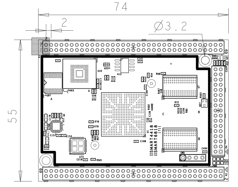
- For more details refer to the dxf file:Smart4418-1711-Drawing(dxf).zip

5 Notes in Hardware Design
5.1 EEPROM
- The Smart4418 CPU board has an EEPROM(model: 24AA025E48T-I/OT) with a unique MAC. This EEPROM is connected to I2C0 and its address is 0x51 therefore some EEPROM chips cannot be connected to I2C0 which will cause conflicts of addresses.
- In our tests these EEPROM chips cannot be connected to I2C0: 24C04, 24C08 and 24C16. There chips which we tested can be connected to I2C0: 24C01, 24C02 and 24C256
- For more details about EEPROM address issues refer to http://www.onsemi.com/pub_link/Collateral/CAT24C01-D.PDF
6 Carrier Board
7 Get Started
7.1 Essentials You Need
Before starting to use your Smart4418 get the following items ready
- Smart4418 CPU board and Smart210/4418 SDK carrier board
- Standard SD card: Class10 or above 8GB SDHC card
- A DC 12V/2A power is a must
- HDMI monitor or LCD
- USB keyboard and mouse
- A host computer running Ubuntu 14.04 64 bit system
7.2 Boot from SD Card
Get the following files from here download link:
- Get a 8G SDHC card and backup its data if necessary.
| Image Files | |
| s5p4418-sd-friendlycore-xenial-4.4-armhf-YYYYMMDD.img.zip | FriendlyCore with Qt 5.10.0 (base on Ubuntu core) image file |
| s5p4418-sd-lubuntu-desktop-xenial-4.4-armhf-YYYYMMDD.img.zip | LUbuntu Desktop image file with X Window |
| s5p4418-sd-friendlywrt-4.4-YYYYMMDD.img.zip | FriendlyWrt image file (base on OpenWrt) |
| s5p4418-sd-android7-YYYYMMDD.img.zip | Android7 image file |
| s5p4418-sd-android-kitkat-YYYYMMDD.img.zip | Android4.4 image file with support for 4G LTE |
| s5p4418-sd-android-lollipop-YYYYMMDD.img.zip | Android5.1 image file |
| s5p4418-eflasher-lubuntu-desktop-xenial-4.4-armhf-YYYYMMDD.img.zip | SD card image, which is used to install a lubuntu desktop to eMMC |
| s5p4418-eflasher-friendlywrt-4.4-YYYYMMDD.img.zip | SD card image, which is used to install a FriendlyWrt to eMMC |
| s5p4418-eflasher-android7-YYYYMMDD.img.zip | SD card image, which is used to install a android7 to eMMC |
| s5p4418-eflasher-friendlycore-xenial-4.4-armhf-YYYYMMDD.img.zip | SD card image, which is used to install a friendly-core to eMMC |
| s5p4418-eflasher-android-kitkat-YYYYMMDD.img.zip | SD card image, which is used to install a android4 to eMMC |
| s5p4418-eflasher-android-lollipop-YYYYMMDD.img.zip | SD card image, which is used to install a android5 to eMMC |
| Flash Utility: | |
| win32diskimager.rar | Windows utility. Under Linux users can use "dd" |
- Uncompress these files. Insert an SD card(at least 4G) into a Windows PC and run the win32diskimager utility as administrator. On the utility's main window select your SD card's drive, the wanted image file and click on "write" to start flashing the SD card.
- Insert this card into your board's boot slot, press and hold the boot key (only applies to a board with onboard eMMC) and power on (with a 5V/2A power source). If the PWR LED is on and LED1 is blinking this indicates your board has successfully booted.
7.3 Flash image to eMMC with eflasher
- Download eflasher image file
An image file's name is as : s5p4418-eflasher-OSNAME-YYYYMMDD.img.zip
The "OSNAME" is the name of an OS e.g. android, friendlycore and etc;
This image file is used for making an installation SD card and it contains a Ubuntu core system and a utility EFlasher;
Download s5p4418-eflasher-OSNAME-YYYYMMDD.img.zip to a host PC and get a windows utility win32diskimager.rar as well;
- Make Installation SD Card with eflasher
Extract the package with a 7z utility and you will get a file with an extension ".img". Insert an SDHC card(minimum 8G or above) to a PC running Windows, run the Win32DiskImager utility as administrator, click on "Image File" to select your wanted file, select your SD card and click on "Write" to start flashing the Image to your SD card;
If your PC runs Linux you can command "dd" to extract the package and get an ".img" file and write it to your SD card;
- Operate in GUI Window: Flash OS to eMMC
Insert your SD card to Smart4418, connect an HDMI monitor or LCD to your board, press and hold the "boot" key beside the Ethernet port, power on the board you will see a pop-up window asking you to select an OS for installation. Select your wanted OS and start installation.
- Operate in Commandline Utility: Flash OS to eMMC
Insert an installation SD card to Smart4418, log into or SSH to your board and run the following command to start EFlasher:
sudo eflasher7.3.1 Make Installation Card under Linux Desktop
- 1) Insert your SD card into a host computer running Ubuntu and check your SD card's device name
dmesg | tail
Search the messages output by "dmesg" for similar words like "sdc: sdc1 sdc2". If you can find them it means your SD card has been recognized as "/dev/sdc". Or you can check that by commanding "cat /proc/partitions"
- 2) Downlaod Linux script
git clone https://github.com/friendlyarm/sd-fuse_s5p4418.git
cd sd-fuse_s5p4418
- 3) Here is how to make a Lubuntu desktop SD card
sudo ./fusing.sh /dev/sdx lubuntu
(Note: you need to replace "/dev/sdx" with the device name in your system)
When you run the script for the first time it will prompt you to download an image you have to hit “Y” within 10 seconds otherwise you will miss the download
- 4) Run this command to make a complete image file:
sudo ./mkimage.sh lubuntu
More content please refre: Assembling the SD card image yourself
7.4 Extend SD Card Section
- When Debian/Ubuntu is loaded the SD card's section will be automatically extended.
- When Android is loaded you need to run the following commands on your host PC to extend your SD card's section:
sudo umount /dev/sdx?
sudo parted /dev/sdx unit % resizepart 4 100 resizepart 7 100 unit MB print
sudo resize2fs -f /dev/sdx7
(Note: you need to replace "/dev/sdx" with the device name in your system)
7.5 LCD/HDMI Resolution
When the system boots our uboot will check whether it is connected to an LCD or to an HDMI monitor. If it recognizes an LCD it will configure its resolution. Our uboot defaults to the HDMI 720P configuration.
If you want to modify the LCD resolution you can modify file "arch/arm/plat-s5p4418/nanopi2/lcds.c" in the kernel and recompile it.
If your Smart4418 is connected to an HDMI monitor and it runs Android it will automatically set the resolution to an appropriate HDMI mode by checking the "EDID". If your Smart4418 is connected to an HDMI monitor and it runs Debian by default it will set the resolution to the HDMI 720P configuration. If you want to modify the HDMI resolution to 1080P modify your kernel's configuration as explained above.
7.6 Update SD Card's boot parameters From PC Host
Insert your SD card into a host PC running Linux, if you want to change your kernel command line parameters you can do it via the fw_setevn utility.
Check the current Command Line:
git clone https://github.com/friendlyarm/sd-fuse_s5p4418.git
cd sd-fuse_s5p4418/tools
./fw_printenv /dev/sdx | grep bootargs
For example, to disable android SELinux, You can change it this way:
./fw_setenv /dev/sdc bootargs XXX androidboot.selinux=permissive
The "XXX" stands for the original bootargs' value.
7.7 Run Android or Linux (TODO)
- 将制作好SD卡插入Smart4418,连接HDMI,按住靠近网口的boot按键,最后接电源(5V 2A)拨动开关,Smart4418会从SD卡启动。你可以看到板上PWR灯常亮,LED1灯闪烁,这说明系统已经开始启动了,同时电视上也将能看到系统启动的画面。
- 要在电视上进行操作,你需要连接USB鼠标和键盘;如果你选购了LCD配件,则可以直接使用LCD上面的触摸屏进行操作。
8 Work with FriendlyCore
8.1 Introduction
FriendlyCore is a light Linux system without X-windows, based on ubuntu core, It uses the Qt-Embedded's GUI and is popular in industrial and enterprise applications.
Besides the regular Ubuntu core's features our FriendlyCore has the following additional features:
- it supports our LCDs with both capacitive touch and resistive touch(S700, X710, HD702, S430, HD101 and S70)
- it supports WiFi
- it supports Ethernet
- it supports Bluetooth and has been installed with bluez utilities
- it supports audio playing
- it supports Qt 5.10.0 EGLES and OpenGL ES1.1/2.0 (Only for S5P4418/S5P6818)
8.2 System Login
- If your board is connected to an HDMI monitor you need to use a USB mouse and keyboard.
- If you want to do kernel development you need to use a serial communication board, ie a PSU-ONECOM board, which will
For example, NanoPi-M1:
You can use a USB to Serial conversion board too.
Make sure you use a 5V/2A power to power your board from its MicroUSB port:
For example, NanoPi-NEO2:
- FriendlyCore User Accounts:
Non-root User:
   User Name: pi
   Password: pi
Root:
   User Name: root
   Password: fa
The system is automatically logged in as "pi". You can do "sudo npi-config" to disable auto login.
- Update packages
$ sudo apt-get update
8.3 Configure System with npi-config
The npi-config is a commandline utility which can be used to initialize system configurations such as user password, system language, time zone, Hostname, SSH switch , Auto login and etc. Type the following command to run this utility.
$ sudo npi-config
Here is how npi-config's GUI looks like:

8.4 Develop Qt Application
Please refer to: How to Build and Install Qt Application for FriendlyELEC Boards
8.5 Setup Program to AutoRun
You can setup a program to autorun on system boot with npi-config:
sudo npi-configGo to Boot Options -> Autologin -> Qt/Embedded, select Enable and reboot.
8.6 Extend TF Card's Section
When FriendlyCore is loaded the TF card's section will be automatically extended.You can check the section's size by running the following command:
$ df -h
8.7 Transfer files using Bluetooth
Take the example of transferring files to the mobile phone. First, set your mobile phone Bluetooth to detectable status, then execute the following command to start Bluetooth search.:
hcitool scan
Search results look like:
Scanning ...
    2C:8A:72:1D:46:02   HTC6525LVW
This means that a mobile phone named HTC6525LVW is searched. We write down the MAC address in front of the phone name, and then use the sdptool command to view the Bluetooth service supported by the phone:
sdptool browser 2C:8A:72:1D:46:02
Note: Please replace the MAC address in the above command with the actual Bluetooth MAC address of the mobile phone.
This command will detail the protocols supported by Bluetooth for mobile phones. What we need to care about is a file transfer service called OBEX Object Push. Take the HTC6525LVW mobile phone as an example. The results are as follows:
Service Name: OBEX Object Push
Service RecHandle: 0x1000b
Service Class ID List:
  "OBEX Object Push" (0x1105)
Protocol Descriptor List:
  "L2CAP" (0x0100)
  "RFCOMM" (0x0003)
    Channel: 12
  "OBEX" (0x0008)
Profile Descriptor List:
  "OBEX Object Push" (0x1105)
    Version: 0x0100
As can be seen from the above information, the channel used by the OBEX Object Push service of this mobile phone is 12, we need to pass it to the obexftp command, and finally the command to initiate the file transfer request is as follows:
obexftp --nopath --noconn --uuid none --bluetooth -b 2C:8A:72:1D:46:02 -B 12 -put example.jpg
Note: Please replace the MAC address, channel and file name in the above command with the actual one.
After executing the above commands, please pay attention to the screen of the mobile phone. The mobile phone will pop up a prompt for pairing and receiving files. After confirming, the file transfer will start.
Bluetooth FAQ:
1) Bluetooth device not found on the development board, try to open Bluetooth with the following command:
rfkill unblock 02) Prompt can not find the relevant command, you can try to install related software with the following command:
apt-get install bluetooth bluez obexftp openobex-apps python-gobject ussp-push8.8 WiFi
For either an SD WiFi or a USB WiFi you can connect it to your board in the same way. The APXX series WiFi chips are SD WiFi chips. By default FriendlyElec's system supports most popular USB WiFi modules. Here is a list of the USB WiFi modules we tested:
Index Model 1 RTL8188CUS/8188EU 802.11n WLAN Adapter 2 RT2070 Wireless Adapter 3 RT2870/RT3070 Wireless Adapter 4 RTL8192CU Wireless Adapter 5 mi WiFi mt7601 6 5G USB WiFi RTL8821CU 7 5G USB WiFi RTL8812AU
You can use the NetworkManager utility to manage network. You can run "nmcli" in the commandline utility to start it. Here are the commands to start a WiFi connection:
- Change to root
$ su root
- Check device list
$ nmcli devNote: if the status of a device is "unmanaged" it means that device cannot be accessed by NetworkManager. To make it accessed you need to clear the settings under "/etc/network/interfaces" and reboot your system.
- Start WiFi
$ nmcli r wifi on- Scan Surrounding WiFi Sources
$ nmcli dev wifi- Connect to a WiFi Source
$ nmcli dev wifi connect "SSID" password "PASSWORD" ifname wlan0
The "SSID" and "PASSWORD" need to be replaced with your actual SSID and password.If you have multiple WiFi devices you need to specify the one you want to connect to a WiFi source with iface
If a connection succeeds it will be automatically setup on next system reboot.
For more details about NetworkManager refer to this link: Use NetworkManager to configure network settings
If your USB WiFi module doesn't work most likely your system doesn't have its driver. For a Debian system you can get a driver from Debian-WiFi and install it on your system. For a Ubuntu system you can install a driver by running the following commands:
$ apt-get install linux-firmware
In general all WiFi drivers are located at the "/lib/firmware" directory.
8.9 Ethernet Connection
If a board is connected to a network via Ethernet before it is powered on it will automatically obtain an IP with DHCP activated after it is powered up. If you want to set up a static IP refer to: Use NetworkManager to configure network settings。
8.10 Custom welcome message
The welcome message is printed from the script in this directory:
/etc/update-motd.d/
For example, to change the FriendlyELEC LOGO, you can change the file /etc/update-motd.d/10-header. For example, to change the LOGO to HELLO, you can change the following line:
TERM=linux toilet -f standard -F metal $BOARD_VENDOR
To:
TERM=linux toilet -f standard -F metal HELLO
8.11 Modify timezone
For exampe, change to Shanghai timezone:
sudo rm /etc/localtime
sudo ln -ls /usr/share/zoneinfo/Asia/Shanghai /etc/localtime
8.12 Select the system default audio device
You can set the system default audio device by following the steps below.
Use the following command to view all the sound card devices in the system (Note: different development boards will have different results):
pi@NanoPi:~$ aplay -l
**** List of PLAYBACK Hardware Devices ****
card 0: nanopi2audio [nanopi2-audio], device 0: c0055000.i2s-ES8316 HiFi ES8316 HiFi-0 []
  Subdevices: 1/1
  Subdevice #0: subdevice #0
card 0: nanopi2audio [nanopi2-audio], device 1: c0059000.spdiftx-dit-hifi dit-hifi-1 []
  Subdevices: 1/1
  Subdevice #0: subdevice #0
As you can see, the following sound card devices are available on the hardware:
Sound card device Sound card number Description nanopi2audio device 0 3.5mm jack interface nanopi2audio device 1 HDMI
To configure the audio output to the 3.5mm jack, create or modify the configuration file /etc/asound.conf and modify it to the following:
pcm.!default {
    type hw
    card 0
    device 0
}

ctl.!default {
    type hw
    card 0
}
To configure to output audio to HDMI, change the device 0 above to device 1.
8.13 Run the X11 application
FriendlyCore system built-in lightweight Xorg,although there is no window manager, you can still run a single X-Windows application,For example, the program to run is ~/YourX11App,use the following command:
. /usr/bin/setqt5env-xcb
startx ~/YourX11App -geometry 1280x800
Note that there is a space between "." and /usr/bin/setqt5env-xcb. In addition, the resolution after -geometry should be changed to the actual resolution of your screen.
8.14 Run Qt 5.10.0 Demo with GPU acceleration
Run the following command
$ sudo qt5demo

8.15 Run Qt 5.10.0 Demo with OpenGL
Run the following command
. setqt5env
cd $QTDIR
cd /examples/opengl/qopenglwidget
./qopenglwidget
For more Qt 5.10.0 examples, please go to:
cd $QTDIR/examples/
8.16 Play HD Video with Hardware-decoding
gst-player is console player, it base on GStreamer, support VPU with Hardware-decoding:
sudo gst-player /home/pi/demo.mp4
The equivalent gsteamer command is as follows:
sudo gst-launch-1.0 filesrc location=/home/pi/demo.mp4 ! qtdemux name=demux demux. ! queue ! faad ! audioconvert ! audioresample ! alsasink device="hw:0,DEV=1" demux. ! queue ! h264parse ! nxvideodec ! nxvideosink dst-x=0 dst-y=93 dst-w=1280 dst-h=533
8.17 Connect to DVP Camera CAM500B
The CAM500B camera module is a 5M-pixel camera with DVP interface. For more tech details about it you can refer to Matrix - CAM500B.
Enter the following command to preview the video:
gst-launch-1.0 -e v4l2src device=/dev/video6 ! video/x-raw,format=I420,framerate=30/1,width=1280,height=720 ! nxvideosink
Enter the following command to start recording (VPU hardware encoding):
gst-launch-1.0 -e v4l2src device=/dev/video6 ! video/x-raw,format=I420,framerate=30/1,width=1280,height=720 ! tee name=t t. \
 ! queue ! nxvideosink t. ! queue ! nxvideoenc bitrate=12000000 ! mp4mux ! \
 filesink location=result_720.mp4
8.18 Power Off and Schedule Power On
“PMU Power Management” feature helps us to auto power on the board at a specific time, it is implemented by an MCU, support software power-off, and RTC alarm power-up functions.
Here’s a simple guide:
Turn on automatically after 100 seconds. (Time must be greater than 60 seconds.):
$ sudo echo 100 > /sys/class/i2c-dev/i2c-3/device/3-002d/wakealarm
After setting up the automatic boot, turn off board with the 'poweroff’ command:
$ sudo poweroff
Cancel automatic boot:
$ sudo echo 0 > /sys/class/i2c-dev/i2c-3/device/3-002d/wakealarm
Query the current settings, in the front is current time, followed by the time of automatic booting: If no automatic boot is set, it will display "disabled”.
$ sudo cat /sys/class/i2c-dev/i2c-3/device/3-002d/wakealarm
Note that some older versions of hardware may not support this feature, if you don't see this file node in your system:
/sys/class/i2c-dev/i2c-3/device/3-002d/wakealarm
your board may be it does not support this feature.
8.19 Installing and Using OpenCV 4.1.2
OpenCV has been pre-installed in FriendlyCore (Version after 20191126) and does not require manual installation.
Please refre this link: https://github.com/friendlyarm/install-opencv-on-friendlycore/blob/s5pxx18/README.md
Quick test:
. /usr/bin/cv-env.sh
. /usr/bin/setqt5env-eglfs
cd /usr/local/share/opencv4/samples/python
python3 turing.py
8.20 Installing and Using Caffe
git clone https://github.com/friendlyarm/install-caffe-on-friendlycore
cd install-caffe-on-friendlycore
sudo ./install-caffe.sh
8.21 How to install and use docker (for armhf system)
8.21.1 How to Install Docker
Run the following commands:
sudo apt-get update
sudo apt-get install docker.io
8.21.2 Test Docker installation
Test that your installation works by running the simple docker image:
git clone https://github.com/friendlyarm/debian-jessie-arm-docker
cd debian-jessie-arm-docker
./rebuild-image.sh
./run.sh
9 Work with Android
9.1 Work with 4G Module EC20 under Android5
9.1.1 Hardware Setup
Connect an EC20 module to miniPCIe port:

Power on the board and you will be able to surf the internet with the 4G module like using an Android phone.
9.2 Connect Smart4418 to 4G Module
- The Smart4418 can work with some 4G modules under Android 4.4. After you connect a 4G module (e.g. ME909u-521 which supports FDD-LTE) to a Smart4418 power on the board the 4G module will be activated automatically

9.3 Modify the Android boot Logo
Replace the logo.bmp:
/opt/FriendlyARM/smart4418/android/device/friendly-arm/nanopi3/boot/logo.bmp
/opt/FriendlyARM/smart4418/android/device/friendly-arm/nanopi2/boot/logo.bmp
Replace the bootanimation.zip:
/opt/FriendlyARM/smart4418/android/device/friendly-arm/nanopi3/bootanimation.zip
/opt/FriendlyARM/smart4418/android/device/friendly-arm/nanopi2/bootanimation.zip
Re-compile android.
9.4 Use fastboot command to flash android firmware
Enter the uboot command line mode on the serial terminal when powering on, and then enter the following command:
fastboot 0For S5P4418:
fastboot flash partmap partmap.txt
fastboot flash 2ndboot bl1-mmcboot.bin
fastboot flash fip-loader loader-mmc.img
fastboot flash fip-secure bl_mon.img
fastboot flash fip-nonsecure bootloader.img
fastboot flash boot boot.img
fastboot flash system system.img
fastboot flash cache cache.img
fastboot flash userdata userdata.img
For S5P6818:
fastboot flash partmap partmap.txt
fastboot flash 2ndboot bl1-mmcboot.bin
fastboot flash fip-loader fip-loader.img
fastboot flash fip-secure fip-secure.img
fastboot flash fip-nonsecure fip-nonsecure.img
fastboot flash boot boot.img
fastboot flash system system.img
fastboot flash cache cache.img
fastboot flash userdata userdata.img
9.5 Android Keys
Android 5:
vendor/friendly-arm/nanopi3/security/
Android 7:
build/target/product/security/
9.6 Optimizing HDMI Performance on Android 7
9.6.1 Note
By default, the driver initializes two framebuffers, one for the primary LCD display and the other for HDMI. If your project specifically requires the use of HDMI and not the LCD, you can follow the steps outlined in this chapter to make modifications. After making these changes, HDMI will be configured as the primary display, resulting in the initialization of only one framebuffer. This optimization conserves resources and leads to corresponding improvements in UI performance and boot speed.
The content of this chapter is applicable exclusively to S5P6818 running Android 7. For S5P4418, the modification process is similar, with adjustments needed in the corresponding files.
9.6.2 Modify the kernel
You need to modify the kernel Device Tree Source (DTS) to disable the dp_drm_lvds node, as shown below:
--- a/arch/arm64/boot/dts/nexell/s5p6818-nanopi3-common.dtsi
+++ b/arch/arm64/boot/dts/nexell/s5p6818-nanopi3-common.dtsi
@@ -810,6 +810,7 @@
                        plane-names = "video", "rgb", "primary";
                };
                port@1 {
+                       status = "disabled";
                        reg = <1>;
                        back_color = < 0x0 >;
                        color_key = < 0x0 >;
@@ -820,7 +821,7 @@

 &dp_drm_lvds {
        remote-endpoint = <&lcd_panel>;
-       status = "ok";
+       status = "disabled";

        display-timing {
                clock-frequency = <50000000>;
After compilation, you will obtain a new arch/arm64/boot/dts/nexell/s5p6818-nanopi3-rev*.dtb file.
During the testing phase, you can directly update it to the board using adb with the following command:
adb root; adb wait-for-device; adb shell mkdir /storage/sdcard1/; adb
shell mount -t ext4 /dev/block/mmcblk0p1 /storage/sdcard1/
adb push arch/arm64/boot/dts/nexell/s5p6818-nanopi3-rev*.dtb /storage/sdcard1/
For a complete firmware update, you will need to replace the files in the device/friendlyelec/nanopi3/boot directory of the Android 7 source code.
9.6.3 Modify env.conf
To modify the device/friendlyelec/nanopi3/boot/env.conf file and add a line
lcdtype HDMI1080P60
This mode needs to match the mode detected by Android 7 after startup; otherwise, it may result in a prolonged black screen state or even no display output. In such cases, you may need to manually set it in the U-Boot command-line environment:
setenv lcdtype HDMI1080P60; saveenv; reset
9.6.4 Modify system.prop
To modify the device/friendlyelec/nanopi3/system.prop file in Android 7
ro.sf.lcd_density=240Alternatively, you can adjust the system property or experiment with different values that you deem more appropriate. You can also use the following command to change the display density under the serial or adb environment and observe if the effect is suitable:
adb shell wm density 2409.6.5 Compiling Android
Follow the instructions in the wiki to compile Android 7 and conduct testing. If you encounter any exceptions, please carefully review the preceding steps.
10 Make Your Own OS Image
10.1 Install Cross Compiler
10.1.1 Install arm-linux-gcc 4.9.3
Download the compiler package:
git clone https://github.com/friendlyarm/prebuilts.git -b master --depth 1
cd prebuilts/gcc-x64
cat toolchain-4.9.3-armhf.tar.gz* | sudo tar xz -C /
Then add the compiler's directory to "PATH" by appending the following lines in "~/.bashrc":
export PATH=/opt/FriendlyARM/toolchain/4.9.3/bin:$PATH
export GCC_COLORS=auto
Execute "~/.bashrc" to make the changes take effect. Note that there is a space after the first ".":
. ~/.bashrcThis compiler is a 64-bit one therefore it cannot be run on a 32-bit Linux machine. After the compiler is installed you can verify it by running the following commands:
arm-linux-gcc -v
Using built-in specs.
COLLECT_GCC=arm-linux-gcc
COLLECT_LTO_WRAPPER=/opt/FriendlyARM/toolchain/4.9.3/libexec/gcc/arm-cortexa9-linux-gnueabihf/4.9.3/lto-wrapper
Target: arm-cortexa9-linux-gnueabihf
Configured with: /work/toolchain/build/src/gcc-4.9.3/configure --build=x86_64-build_pc-linux-gnu
--host=x86_64-build_pc-linux-gnu --target=arm-cortexa9-linux-gnueabihf --prefix=/opt/FriendlyARM/toolchain/4.9.3
--with-sysroot=/opt/FriendlyARM/toolchain/4.9.3/arm-cortexa9-linux-gnueabihf/sys-root --enable-languages=c,c++
--with-arch=armv7-a --with-tune=cortex-a9 --with-fpu=vfpv3 --with-float=hard
...
Thread model: posix
gcc version 4.9.3 (ctng-1.21.0-229g-FA)
10.2 Compile Linux kernel for FriendlyCore/Lubuntu/EFlasher
10.2.1 Compile Kernel
- Download Kernel Source Code
git clone https://github.com/friendlyarm/linux.git -b nanopi2-v4.4.y --depth 1
cd linux
The Smart4418's kernel source code is in the "nanopi2-v4.4.y" branch.You need to switch to this branch.
- Compile Ubuntu Kernel
touch .scmversion
make ARCH=arm nanopi2_linux_defconfig
make ARCH=arm
After your compilation succeeds an "arch/arm/boot/zImage" will be generated and a DTB file(s5p4418-nanopi2-rev*.dtb) will be generated in the "arch/arm/boot/dts/" directory. You can use them to replace the existing zImage and DTB files in the boot partition of your bootable SD card.
10.2.2 Use Your Generated Kernel
- Update kernel in SD card
If you use an SD card to boot Ubuntu you can copy your generated zImage and DTB files to your SD card's boot partition(e.g. partition 1 /dev/sdX1).
- Update kernel in eMMC
If you boot your board from eMMC you can update your kernel file by following the steps below:
1) Usually after OS is loaded eMMC's boot partition (in our example eMMC's device name was /dev/mmcblk0p1) will be automatically mounted and you can verify that by running "mount"
2) Connect your board to a host PC running Ubuntu and copy the zImage and DTB files to eMMC's boot partition
3) Or you can copy your generated kernel file to an external storage card(e.g. an SD card or a USB drive), connect the storage card to your board the move the file from the card to eMMC's boot partition
4) After update is done type "reboot" to reboot your board. Note: don't just directly disconnect your board from its power source or press the reset button to reboot the board. These actions will damage your kernel file
- Generate Your boot.img
Refer to this repo: https://github.com/friendlyarm/sd-fuse_s5p4418
10.3 Compile Linux kernel for Android7
The Android 7.1.2 source code already contains the pre-compiled kernel. If you need to customize it, you can compile the kernel according to the following guide.
git clone https://github.com/friendlyarm/linux.git -b nanopi2-v4.4.y --depth 1
cd linux
touch .scmversion
make ARCH=arm nanopi2_nougat_defconfig
make ARCH=arm
The newly generated kernel is arch/arm/boot/zImage,The new DTB file is also included under the directory arch/arm/boot/dts/.(s5p4418-nanopi2-rev*.dtb).
If you only want to debug the kernel, you can quickly update it with adb:
adb root; adb shell mkdir /storage/sdcard1/; adb shell mount -t ext4 /dev/block/mmcblk0p1 /storage/sdcard1/;
adb push arch/arm/boot/zImage arch/arm/boot/dts/s5p4418-nanopi2-rev*.dtb /storage/sdcard1/
If you want to generate boot.img for burning, you can copy the kernel zImage and DTB files to the Android7 source code directory: device/friendlyelec/nanopi2/boot, then recompile Android7.
10.4 Compile U-Boot for Android7/FriendlyCore/Lubuntu/EFlasher
Download the U-Boot source code and compile it. Note that the github's branch is nanopi2-v2016.01:
git clone https://github.com/friendlyarm/u-boot.git
cd u-boot
git checkout nanopi2-v2016.01
make s5p4418_nanopi2_defconfig
make CROSS_COMPILE=arm-linux-
After your compilation succeeds a bootloader.img will be generated. If you want to test it flash it to your installation SD card to replace an existing U-Boot v2016.01 file via fastboot, sd-fuse_s5p4418 or eflasher ROM.
For Android7: Copy bootloader.img to Android7 source directory device/friendlyelec/nanopi2/boot, then recompile Android7.
Note: you cannot use mixed U-Boot files. For example you cannot use fastboot to update an existing U-Boot V2014.07 and you cannot use bootloader.img to replace an existing u-boot.bin
10.5 Compile Android 7.1.2
10.5.1 Install Cross Compiler
Install 64 bit Ubuntu 16.04 on your host PC.
sudo apt-get install bison g++-multilib git gperf libxml2-utils make python-networkx zip
sudo apt-get install flex curl libncurses5-dev libssl-dev zlib1g-dev gawk minicom
sudo apt-get install openjdk-8-jdk
sudo apt-get install exfat-fuse exfat-utils device-tree-compiler liblz4-tool
For more details refer to https://source.android.com/source/initializing.html 。
10.5.2 Download Android7 Source Code
There are two ways to download the source code:
- repo archive file on netdisk
Netdisk URL: Click here
File location on netdisk:sources/s5pxx18-android-7.git-YYYYMMDD.tar (YYYYMMDD means the date of packaging)
After extracting the repo package from the network disk, you need to execute the sync.sh script, which will pull the latest code from gitlab:
tar xvf /path/to/netdisk/sources/s5pxx18-android-7.git-YYYYMMDD.tar
cd s5pxx18-android-7
./sync.sh
- git clone from gitlab
Smart4418 source code is maintained in gitlab, You can download it by running the following command:
git clone https://gitlab.com/friendlyelec/s5pxx18-android-7.git -b master
10.5.3 Compile Android7
cd s5pxx18-android-7
source build/envsetup.sh
lunch aosp_nanopi2-userdebug
make -j8
After your compilation succeeds the following files will be generated in the "out/target/product/nanopi2/" directory.
filename partition Description bl1-mmcboot.bin raw boot firmware loader-mmc.img raw boot firmware bl_mon.img raw boot firmware bootloader.img raw uboot-v2016.01 env.conf - Uboot environment variable containing Android kernel command line parameters boot.img boot kernel zImage, DTBs; logo; Android ramdisk cache.img cache - userdata.img userdata - system.img system - partmap.txt - Partition description file
11 Build Kernel Headers Package
The following commands need to be executed on the development board:
11.1 Software Version
The OS image file name: s5p4418-sd-friendlycore-xenial-4.4-armhf-YYYYMMDD.img, s5p4418-eflasher-friendlycore-xenial-4.4-armhf-YYYYMMDD.img
pi@NanoPC-T2:~$ lsb_release -a
No LSB modules are available.
Distributor ID: Ubuntu
Description:    Ubuntu 16.04.6 LTS
Release:        16.04
Codename:       xenial
pi@NanoPC-T2:~$ cat /proc/version
Linux version 4.4.172-s5p4418 (root@jensen) (gcc version 7.5.0 (ctng-1.24.0-108g-FA) ) #1 SMP PREEMPT Wed Mar 24 15:17:25 CST 2021
11.2 Install the required packages
sudo apt-get update
sudo apt-get install -y dpkg-dev bsdtar
11.3 Build Kernel Headers Package
git clone https://github.com/friendlyarm/linux -b nanopi2-v4.4.y --depth 1 kernel-s5pxx18-arm
cd kernel-s5pxx18-arm
rm -rf .git
make distclean
touch .scmversion
make CROSS_COMPILE= ARCH=arm nanopi2_linux_defconfig
alias tar=bsdtar
make CROSS_COMPILE= ARCH=arm bindeb-pkg -j4
The following message is displayed to indicate completion:
dpkg-deb: building package 'linux-firmware-image-4.4.172-s5p4418' in '../linux-firmware-image-4.4.172-s5p4418_4.4.172-s5p4418-1_armhf
.deb'.
dpkg-deb: building package 'linux-headers-4.4.172-s5p4418' in '../linux-headers-4.4.172-s5p4418_4.4.172-s5p4418-1_armhf.deb'.
dpkg-deb: building package 'linux-libc-dev' in '../linux-libc-dev_4.4.172-s5p4418-1_armhf.deb'.
dpkg-deb: building package 'linux-image-4.4.172-s5p4418' in '../linux-image-4.4.172-s5p4418_4.4.172-s5p4418-1_armhf.deb'.
dpkg-genchanges: binary-only upload (no source code included)
12 Installation=
sudo rm -f /lib/modules/4.4.172-s5p4418/build
sudo rm -f /lib/modules/4.4.172-s5p4418/source
sudo dpkg -i ../linux-headers-4.4.172-s5p4418_4.4.172-s5p4418-1_armhf.deb
12.1 Testing
To compile the pf_ring module as an example, refer to the documentation: https://www.ntop.org/guides/pf_ring/get_started/git_installation.html.
git clone https://github.com/ntop/PF_RING.git
cd PF_RING/kernel/
make CROSS_COMPILE=
After compiling, use insmod to try to load the module:
sudo insmod ./pf_ring.ko
13 Connect Smart4418 to External Modules
13.1 Connect Smart4418 to USB Camera(FA-CAM202)
- In this use case the Smart4418 runs Debian. If you connect your Smart4418 to our LCD or an HDMI monitor after Debain is fully loaded click on "other"-->"xawtv" on the left bottom of the GUI and the USB Camera application will be started. After enter "welcome to xawtv!" click on "OK" to start exploring.


13.2 Connect Smart4418 to CMOS 5M-Pixel Camera
For more details about the CAM500A camera refer to [1]
- If your Smart4418 runs Android5.1 and it is connected to our LCD or an HDMI monitor after Android is fully loaded click on the "Camera" icon and the application will be started. You can take pictures or record videos

- Under Debian a camera utility "nanocams" is available for previewing 40 frames and picture taking. You can try it by following the commands below
sudo nanocams -p 1 -n 40 -c 4 -o IMG001.jpg
For more details about the usage of the nanocams run "nanocams -h". You can get its source code from our git hub:
git clone https://github.com/friendlyarm/nexell_linux_platform.git
- Under FriendlyCore (kernel 4.4), You can try it by following the commands below:
Enter the following command to preview the video:
gst-launch-1.0 -e v4l2src device=/dev/video6 ! video/x-raw,format=I420,framerate=30/1,width=1280,height=720 ! nxvideosink
Enter the following command to start recording (VPU hardware encoding):
gst-launch-1.0 -e v4l2src device=/dev/video6 ! video/x-raw,format=I420,framerate=30/1,width=1280,height=720 ! tee name=t t. \
 ! queue ! nxvideosink t. ! queue ! nxvideoenc bitrate=12000000 ! mp4mux ! \
 filesink location=result_720.mp4
13.3 Use OpenCV to Access USB Camera
- The full name of "OpenCV" is Open Source Computer Vision Library and it is a cross platform vision library.
- When the Smart4418 runs Debian users can use OpenCV APIs to access a USB Camera device.
1. Here is a guideline on how to use OpenCV with C++ on the Smart4418:
- Firstly you need to make sure your Smart4418 is connected to the internet.Login to your Smart4418 via a serial terminal or SSH. After login type in your username(root) and password(fa):
- Run the following commands:
apt-get update
apt-get install libcv-dev libopencv-dev
2. Make sure your USB camera works with the Smart4418. You can test your camera with Smart4418's camera utility.
3. Check your camera device:
ls /dev/video*
- Note:in our test case video0 was the device name.
4. OpenCV's code sample(official code in C++) is under /home/fa/Documents/opencv-demo. Compile the code sample with the following commands:
cd /home/fa/Documents/opencv-demo
make
After it is compiled successfully a "demo" executable will be generated
5. Connect Smart4418 to USB Keyboard & Run the Following Command:
./demoopencv is successfully started
13.4 Connect Smart4418 to Matrix GPS Module
- The Matrix-GPS module is a small GPS module with high performance. It can be used in navigation devices, four-axle drones and etc.
- The Matrix-GPS module uses serial communication. When the Smart4418 is connected to the Matrix GPS module, after the Smart4418 is powered up type in the following command in a terminal or click on the xgps icon it will be started.
$su - fa -c "DISPLAY=:0 xgps 127.0.0.1:9999"
- Or on the Debian GUI start the LXTerminal, type in "xgps" and enter it will be started too.
For more details about this GPS module refer to Click to check
Refer to the following diagram to connect the Smart4418 to the Matrix-GPS:

Connection Details:
| Matrix-GPS | Smart4418 |
| RXD | Pin11 |
| TXD | Pin12 |
| 5V | Pin29 |
| GND | Pin30 |
14 Access Hardware under Android
FriendlyElec developed a library called “libfriendlyarm-things.so”, for android developer to access the hardware resources on the development board in their android apps, the library is based on Android NDK.
Accessible Modules:
- Serial Port
- PWM
- EEPROM
- ADC
- LED
- LCD 1602 (I2C)
- OLED (SPI)
Interfaces & Ports:
- GPIO
- Serial Port
- I2C
- SPI
Refer to the following url for details:
- Homepage: http://wiki.friendlyelec.com/wiki/index.php/FriendlyThings
- Examples: https://github.com/friendlyarm/friendlythings-examples
- Guide to API: http://wiki.friendlyelec.com/wiki/index.php/FriendlyThings_APIs
15 Connect Smart4418 to FriendlyARM LCD Modules
- Android
Here are the LCDs that are supported under Android:S430, S700/S701, S702, HD700, HD702, HD101 and X710 all of which are LCDs with capacitive touch.
- FriendlyCore & Lubuntu Desktop
Here are the LCDs that are supported under FriendlyCore and Lubuntu Desktop:S430, S700/S701, S702, HD700, HD702, HD101 and X710 all of which are LCDs with capacitive touch;
W35B, H43, P43, S70D and Matrix 2.8" SPI Key TFT LCD all of which are LCDs with resistive touch
All these LCD's tech details can be obtained on our wiki site:LCDModules
16 Schematics & Mechanical drawing
- Smart4418 1512 SchematicPDF
- Smart4418 1608 SchematicPDF
- Smart4418 1711 SchematicPDF
- 尺寸(Smart4418-1512-Dimension(dxf).zip)
- 尺寸(Smart4418-1608-Dimension(dxf).zip)
- 尺寸(Smart4418-1711-Drawing(dxf).zip)
- S5P4418 Datasheet (S5P4418_Datasheet_0.1.pdf)
17 Resources
- 《创客秘籍》Hacker's Book in Chinese by FriendlyARM
- 《创客秘籍-02》Hacker's Book-02 in Chinese by FriendlyARM
- 《创客秘籍-03》Hacker's Book-03 in Chinese by FriendlyARM
- SEC_Users_Manual_S5P4418_Users_Manual_Preliminary[2]
- eMMC eMMC5.0_1xnm_based_e_MMC
- Matrix Modules & Wiki Sites:
- Button
- LED
- A/D Converter
- Relay
- 3-Axis Digital Accelerometer
- 3-Axis Digital Compass
- Temperature Sensor
- Temperature & Humidity Sensor
- Buzzer
- Joystick
- I2C(PCF8574)+LCD1602
- Sound Sensor
- Ultrasonic Ranger
- GPS
- Matrix - Compact Kit
- Fire Sensor
- CAM500A Camera
- BAll Rolling Switch
- 2'8 SPI Key TFT 2.8" SPI LCD
- IR Counter
- IR Receiver
- L298N Motor Driver
- MQ-2 Gas Sensor
- MQ-3 Gas Sensor
- One_Touch_Sensor
- _Photoresistor
- _Potentiometer
- Pressure & Temperature Sensor
- RGB LED
- RTC
- Rotary Encoder
- Soil Moisture Sensor
- Thermistor
- USB WiFi
- Water Sensor
18 Source Code and Image Files Download Links
19 Tech Support
If you have any further questions please visit our forum http://www.friendlyarm.com/Forum/ and post a message or email us at techsupport@friendlyarm.com. We will endeavor to get back to you as soon as possible.
20 Update Log
20.1 2023-01-09
20.1.1 FriendlyCore:
- optimized the systemd service
20.2 2020-10-26
- FriendlyCore, Lubuntu:
Fix Bluetooth stability issue
20.3 2019-12-28
- eflasher:
1) Supports flashing only some files, such as updating only the kernel and uboot in emmc
2) Added gui option to disable overlay filesystem
3) Add command line parameters to achieve one-click installation without interaction
4) Fix the issue that the same mac address will appear on different devices after backup and restore image
5) UI interface can now be configured with title, hide interface menus and buttons
20.4 2019-11-26
- FriendlyCore:
Pre-installed OpenCV 4.1.2
20.5 2019-11-14
- Introducing a new system FriendlyWrt:
FriendlyWrt is a customized OpenWrt system developed by FriendlyElec. It is open source and suitable for applications in IoT, NAS etc.
Please refre: http://wiki.friendlyelec.com/wiki/index.php/How_to_Build_FriendlyWrt
- FriendlyCore, Lubuntu updated as follows:
1) Added support for new 4.3-inch screen YZ43
2) Compile bcmdhd as a module.
- Android7 update is as follows:
1) Added support for new 4.3-inch screen YZ43
2) Optimize the touch experience when using HD900 screen under Android 7 system
3) Optimize the touch experience when using S702 screen under Android 7 system
20.6 2019-10-18
- Android7, FriendlyCore, Lubuntu:
Fixed audio playback issue.
20.7 2019-09-30
- Android7 updated as follows:
1)Added support for Android hardware access library (named FriendlyThing), support access to hardware resources such as GPIO, PWM, RTC, serial port and watchdog, providing open source demo
2) Added support for camera CAM500B (OV5640)
3) Added support for LCD W500 (800x480)
4) Fixed LCD-S430 compatibility issues
- FriendlyCore, FriendlyDesktop updated as follows:
1) Kernel version updated to v4.4.172, same as Android 7
2) Added Docker support, support 32bit and 64bit file systems
3) Kernel configuration items are optimized to enable more features and device drivers
20.8 2019-07-18
- Introducing a new system Android 7.1.2
1) Features similar to the old version of Android 5, support 4G, WiFi, Ethernet, Bluetooth, etc.
2) Kernel version: 4.4.172
3) Known issue: The camera is not working yet
- Android/FriendlyCore/Lubuntu updated as follows:
1) Fix an issue where HD101B can't be touched in some cases
2) Fix GPIO configuration of Power key
3) Solve the problem of too small volume: the volume of the DAC is changed from -20dB to -6dB during playback.
4) Add more models of USB Wi-Fi support, built-in driver rtl8821CU.ko, rtl88XXau.ko
- Updates for Lubuntu only:
1) Modify Lubuntu's Power key behavior to (without pop-ups) shut down directly
2) Add script xrotate.sh to simplify screen rotation settings (Note: screen rotation will lose performance)
- The following updates are only available for NanoPC T2, Smart4418:
Support for reading Ethernet Mac addresses from the onboard EEPROM, only supports the following systems: FriendlyCore, Lubuntu, Android7
20.9 2019-06-25
Linux(Ubuntu 16.04/18.04) uses OverlayFS to enhance filesystem stability.
20.10 2019-06-03
1) Configure LED1 to be in heartbeat mode
2) Fix HDMI 1080P may have no display problem in some cases
3) Fix the issue that mysql cannot be installed under Linux
4) Fix the issue that the 1-wire touch resistance screen cannot be used under lubuntu
20.11 2019-01-24
1) Update uboot-v2014.07, uboot-v2016.01 for HD702V LCD
2) Adjust Qt5 font path
20.12 2018-12-17
- Android5 updated as follows:
1) Add support for 4G network, support module: Quectel EC20
2) Add audio setting UI, you can set the default output to headphones or HDMI
3) Synchronously turn off the backlight of the one-line touch screen when the system Shutdown
- FriendlyCore updated as follows:
1) Add OV5640 camera support
2) Update BL1 to improve system startup stability
- Lubuntu updated as follows:
1) Add Chrome-browser browser, support web page 1080P hardware decoding, support WebGL
2) Set the audio output channel to HDMI by default (can be changed via /etc/asound.conf)
3) Update BL1 to improve system startup stability
4) Fixed some issues regarding the package error in the previous version
5) Adjust DPMS settings, turn off automatic sleep by default
20.13 March-04-2016
- Released English version
20.14 March-09-2016
- Corrected a typo
20.15 March-23-2016
- Added section 11
20.16 March-27-2016
- Corrected expression errors
20.17 April-08-2016
- Added section 6.4.2 and 7.4
- Updated section 6.5
20.18 June-30-2016
- Added section 9 and 10
20.19 Sep-04-2016
- Updated section 5.2.2 and 10.1.1
20.20 Sep-27-2016
- Updated section 5.2.2, 7.5 and 8.2
20.21 Nov-2-2016
- Updated section 6.2, 6.3, 6.4 and 12
20.22 Nov-17-2016
- Added section 10.6
20.23 Dec-7-2016
- Added section 6.6
- Updated section 7.5
20.24 June-13-2016
- Added section 7: added UbuntuCore
- Added section 11.3: added DietPi
20.25 June-20-2016
- Updated sections 6.2 & 6.3: Wireless connection and WiFi AP setting
- Added section 3: software features