Difference between revisions of "CM3588 NAS Kit"
From FriendlyELEC WiKi
(→Schematic, PCB CAD File) |
(→Diagram, Layout and Dimension) |
||
| Line 43: | Line 43: | ||
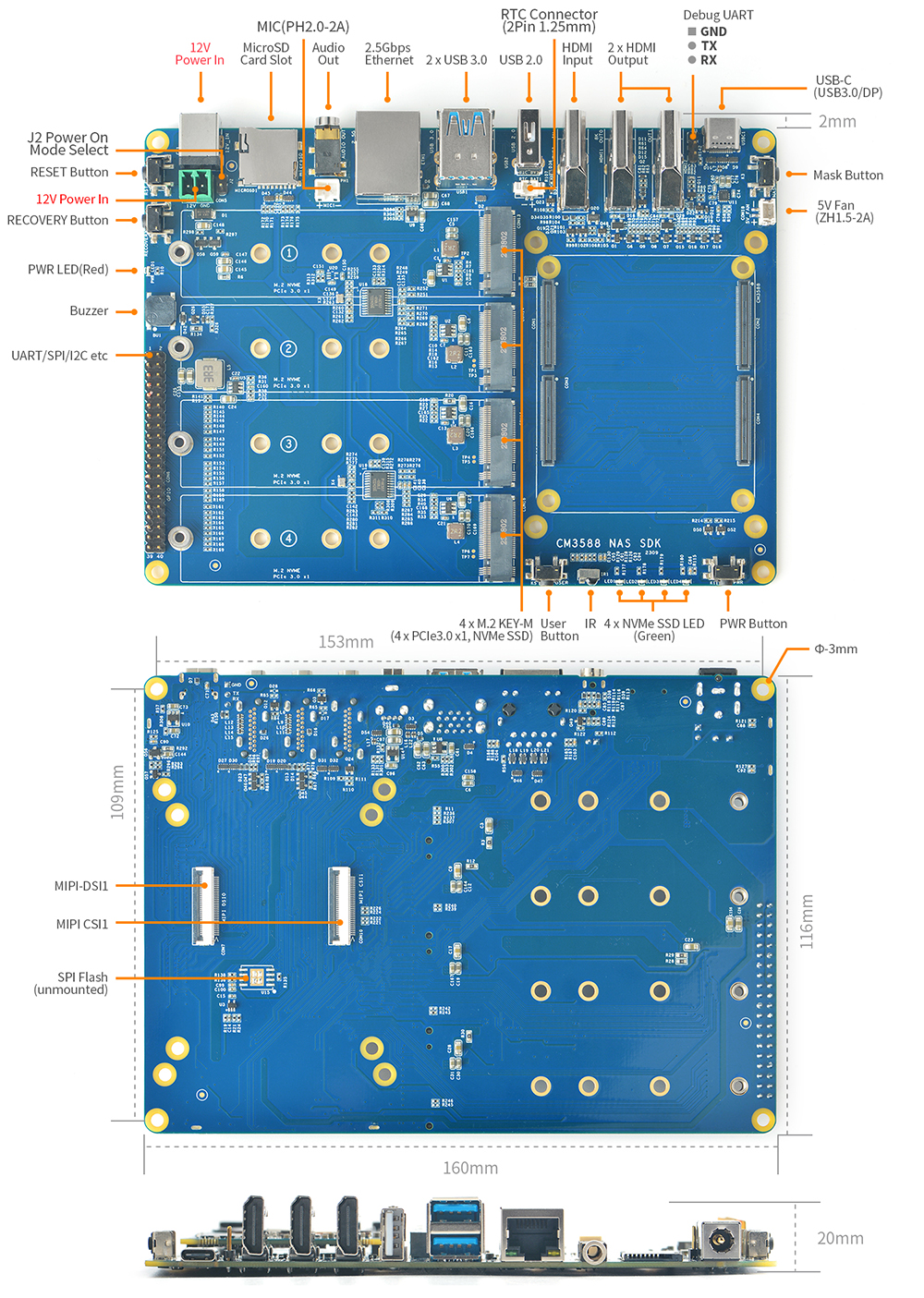
==Diagram, Layout and Dimension== | ==Diagram, Layout and Dimension== | ||
[[File:CM3588 NAS SDK Carrier board layout.jpg|1000px]] | [[File:CM3588 NAS SDK Carrier board layout.jpg|1000px]] | ||
| + | |||
| + | ==Power In== | ||
| + | DC-Jack: 5.5*2.1mm | ||
| + | Green connector: DB2EVC-3.5-2P-GN or compatible part | ||
| + | |||
==Get Started== | ==Get Started== | ||
Link to [[CM3588|CM3588 Wiki Page]] | Link to [[CM3588|CM3588 Wiki Page]] | ||
Revision as of 02:43, 21 May 2024
Contents
[hide]1 Introduction
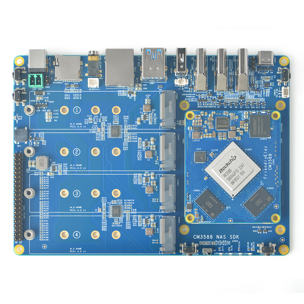
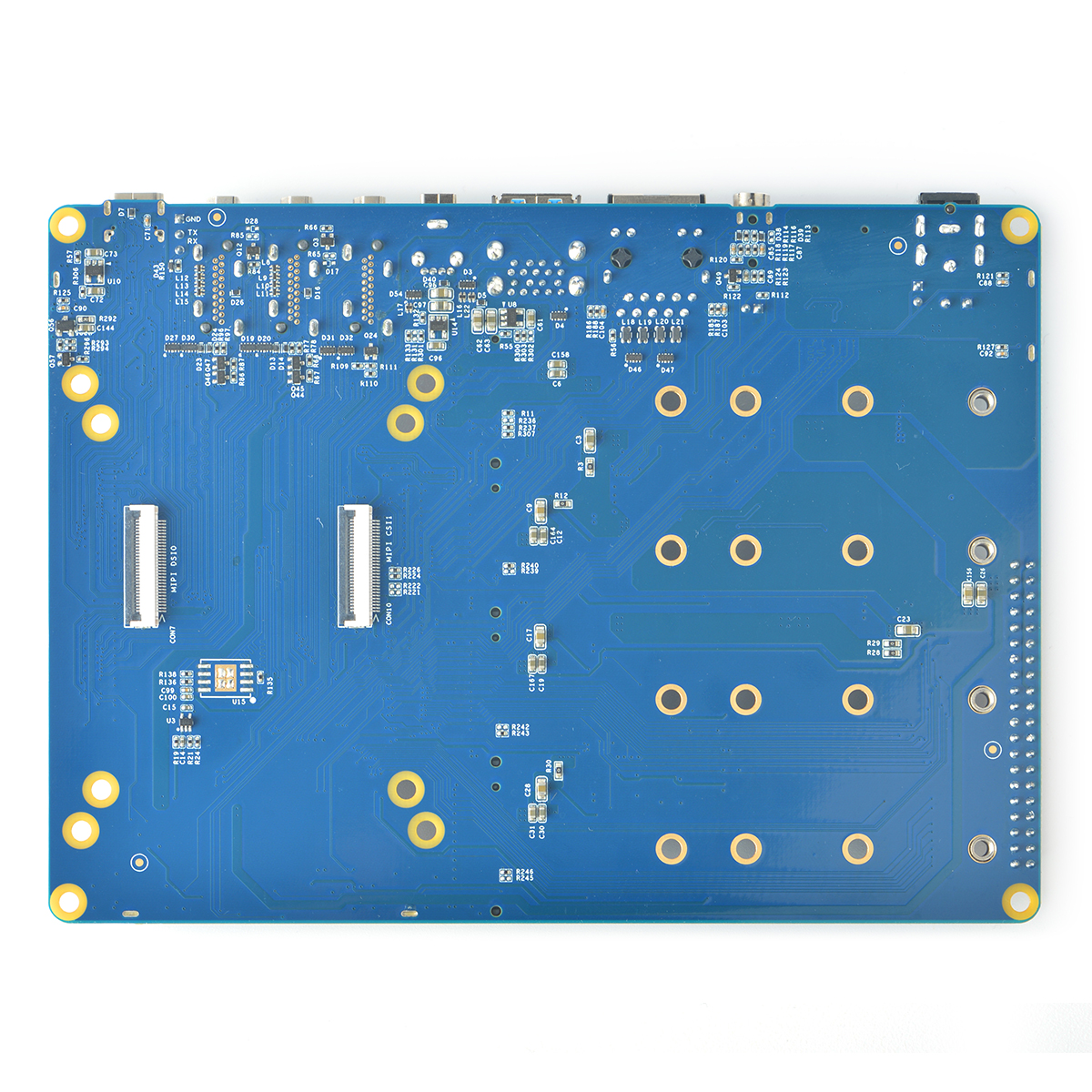
- The CM3588 NAS Kit is a carrier board designed based on the CM3588 core module. It includes 4x M.2 Key M PCIe 3.0 x1 slots, 2x USB3.0 Type-A ports, 1x USB3.0 Type-C interface with DP support, dual HDMI OUT ports and one HDMI IN port, and a 2.5Gbps Ethernet interface.
2 Hardware Spec
- CPU Board: CM3588 based on Rockchip RK3588 SoC
- CPU: Quad-core ARM Cortex-A76(up to 2.4GHz) and quad-core Cortex-A55 CPU (up to 1.8GHz)
- GPU: Mali-G610 MP4, compatible with OpenGLES 1.1, 2.0, and 3.2, OpenCL up to 2.2 and Vulkan1.2
- VPU: 8K@60fps H.265 and VP9 decoder, 8K@30fps H.264 decoder, 4K@60fps AV1 decoder, 8K@30fps H.264 and H.265 encoder
- NPU: 6TOPs, supports INT4/INT8/INT16/FP16
- RAM: 64-bit 4GB/8GB/16GB LPDDR4X at 2133MHz
- Flash: 0GB/64GB eMMC, at HS400 mode
- Codec: On-board ALC5616 Codec
- Low power RTC (HYM8563TS)
- 1 x microSD slot, support up to SDR104 mode
- 1 x 2.5Gbps RJ45 Port
- 1 x USB 3.0 Type-C DRP port, which supports DP display(up to 4Kp60)
- 2 x USB 3.0 Type-A Ports
- 1 x USB 2.0 Type-A Port
- 4 x M.2 M-Key connector with PCIe 3.0 x1 for NVMe SSDs
- 2 x HDMI outputs which is compatible with HDMI2.1, HDMI2.0, and HDMI1.4 operation
- one support displays up to 7680x4320@60Hz, another one support up to 4Kp60
- 1 x HDMI input, up to 4Kp60
- 1 x 4lane MIPI CSI ,compatible with MIPI V1.2
- 1 x 4lane MIPI DSI, compatible with MIPI DPHY 2.0 or CPHY 1.1
- 1 x stereo 3.5mm headphone output Jack ( 20mW/CH, THD+N <= -80dB, 16Ohm Load )
- 1 x 2.0mm PH-2A connector for single-end microphone input
- 1 x 40 Pins 2.54mm GPIO header
- up to 2 x SPIs, 6 x UARTs, 1 x I2Cs, 8 x PWMs, 2x I2Ss, 28 x GPIOs
- others:
- 1 x 2-Pin 1.27/1.25mm RTC battery input connector
- 1 x 38Khz IR receiver
- 1 x 5V Fan connector
- 1 x PWM buzzer
- MASK button for eMMC update, reset button, Power button, recovery mode button, and 1 x User button
- Debug UART, 3-Pin 2.54mm header, 3.3V level, 1500000bps
- 4 x NVME SSD LEDs
- Power supply: 12VDC input
- PCB: 4 Layers, 160*116*1.5mm
- Ambient Operating Temperature: 0℃ to 70℃
3 Diagram, Layout and Dimension
4 Power In
DC-Jack: 5.5*2.1mm Green connector: DB2EVC-3.5-2P-GN or compatible part
5 Get Started
Link to CM3588 Wiki Page
6 Schematic, PCB CAD File
- CM3588 Schematic: https://wiki.friendlyelec.com/wiki/images/0/00/CM3588_2309_SCH.PDF
- CM3588 PCB CAD File:https://wiki.friendlyelec.com/wiki/images/f/f5/CM3588_2309_DXF.zip
- CM3588 NAS SDK Schematic: https://wiki.friendlyelec.com/wiki/images/1/15/CM3588_NAS_SDK_2309_SCH.PDF
- CM3588 NAS SDK PCB CAD File: https://wiki.friendlyelec.com/wiki/images/f/fe/CM3588_NAS_SDK_2309_DXF.zip
- CM3588 NAS SDK PCB layout PDF File: https://wiki.friendlyelec.com/wiki/images/2/2c/CM3588_NAS_SDK_2309_PCB_Layout.pdf
- CM3588 NAS SDK 3D File: https://wiki.friendlyelec.com/wiki/images/2/21/CM3588_NAS_SDK_2309_3D_stp.zip


