Difference between revisions of "NanoPi M2"
(→Nov-03-2016) |
(updated by API) |
||
| (26 intermediate revisions by 5 users not shown) | |||
| Line 12: | Line 12: | ||
==Hardware Spec== | ==Hardware Spec== | ||
* CPU: S5P4418, 400Mhz~1.4GHz | * CPU: S5P4418, 400Mhz~1.4GHz | ||
| − | |||
* DDR3 RAM: 32bit 1GB DDR3 | * DDR3 RAM: 32bit 1GB DDR3 | ||
* MicroSD Slot x1 | * MicroSD Slot x1 | ||
| Line 30: | Line 29: | ||
* Power: DC 5V/2A | * Power: DC 5V/2A | ||
* PCB Dimension(mm): 64 x 56, Six Layer | * PCB Dimension(mm): 64 x 56, Six Layer | ||
| + | * Temperature measuring range: -10℃ to 80℃ | ||
* OS/Software: u-boot, Android5.1/4.4, Debian Jessie 8 | * OS/Software: u-boot, Android5.1/4.4, Debian Jessie 8 | ||
[[File:NanoPi 2M-B03.png|frameless|500px|compact]] | [[File:NanoPi 2M-B03.png|frameless|500px|compact]] | ||
| Line 166: | Line 166: | ||
::# All pins are 3.3V, output current is 5mA | ::# All pins are 3.3V, output current is 5mA | ||
::# GPIO1's pin spec is a little bit different from that of the NanoPi 2. Refer to this comparison table [[40 pins GPIO comparison table]] | ::# GPIO1's pin spec is a little bit different from that of the NanoPi 2. Refer to this comparison table [[40 pins GPIO comparison table]] | ||
| − | ::# For more details refer to the document: [http://wiki. | + | ::# For more details refer to the document: [http://wiki.friendlyelec.com/wiki/images/3/31/NanoPi-M2-1602-Schematic.pdf NanoPi-M2-1602-Schematic.pdf] |
===Board Dimension=== | ===Board Dimension=== | ||
[[File:NanoPi M2_1512B_Dimensions.png|frameless|500px|NanoPi M2 Dimensions]] | [[File:NanoPi M2_1512B_Dimensions.png|frameless|500px|NanoPi M2 Dimensions]] | ||
| − | ::For more details refer to the document: [http://wiki. | + | ::For more details refer to the document: [http://wiki.friendlyelec.com/wiki/images/0/0b/NanoPi-M2-1602-Dimensions%28dxf%29.zip NanoPi-M2-1602-Dimensions(dxf).zip] |
==Get Started== | ==Get Started== | ||
| Line 181: | Line 181: | ||
* HDMI monitor or LCD | * HDMI monitor or LCD | ||
* USB keyboard and mouse | * USB keyboard and mouse | ||
| − | * A | + | * A host computer running Ubuntu 18.04 64 bit system |
| − | + | {{TFCardsWeTested}} | |
| − | + | ||
| − | + | ||
| − | + | ||
| − | + | ||
| − | + | ||
| − | + | ||
| − | + | ||
===Make an Installation MicroSD Card=== | ===Make an Installation MicroSD Card=== | ||
====Under Windows==== | ====Under Windows==== | ||
| − | Get the following files from here:[ | + | Get the following files from here:[http://download.friendlyelec.com/nanopim2 to download image files.<br /> |
* Get a 4G SDHC card and backup its data if necessary.<br/> | * Get a 4G SDHC card and backup its data if necessary.<br/> | ||
<!--- | <!--- | ||
| Line 211: | Line 204: | ||
|s5p4418-android-sd4g-YYYYMMDD.img.zip || Android5.1 image file | |s5p4418-android-sd4g-YYYYMMDD.img.zip || Android5.1 image file | ||
|- | |- | ||
| − | |s5p4418-core-qte-sd4g-YYYYMMDD.img.zip || Ubuntu core with Qt Embedded | + | |s5p4418-ubuntu-core-qte-sd4g-YYYYMMDD.img.zip || Ubuntu core with Qt Embedded |
|- | |- | ||
|colspan=2|Flash Utility: | |colspan=2|Flash Utility: | ||
| Line 246: | Line 239: | ||
*2) Download Flashing Script | *2) Download Flashing Script | ||
<syntaxhighlight lang="bash"> | <syntaxhighlight lang="bash"> | ||
| − | git clone https://github.com/friendlyarm/sd- | + | git clone https://github.com/friendlyarm/sd-fuse_s5p4418.git |
| − | cd sd- | + | cd sd-fuse_s5p4418 |
</syntaxhighlight> | </syntaxhighlight> | ||
| Line 299: | Line 292: | ||
If you want to make some changes to the image files in your MicroSD card follow steps below otherwise you can skip this section.<br/> | If you want to make some changes to the image files in your MicroSD card follow steps below otherwise you can skip this section.<br/> | ||
Insert your MicroSD card into a PC host running Linux, mount the boot and rootfs sections of the SD card and follow the steps below:<br/> | Insert your MicroSD card into a PC host running Linux, mount the boot and rootfs sections of the SD card and follow the steps below:<br/> | ||
| − | 1) If you want to change your kernel command line parameters you can do it via the fw_setevn utility under "sd- | + | 1) If you want to change your kernel command line parameters you can do it via the fw_setevn utility under "sd-fuse_s5p4418/tools".<br /> |
Check the current Command Line: | Check the current Command Line: | ||
<syntaxhighlight lang="bash"> | <syntaxhighlight lang="bash"> | ||
| − | cd sd- | + | cd sd-fuse_s5p4418/tools |
./fw_printenv /dev/sdc | grep bootargs | ./fw_printenv /dev/sdc | grep bootargs | ||
</syntaxhighlight> | </syntaxhighlight> | ||
| Line 324: | Line 317: | ||
[[File:PSU-ONECOM-M2.png|frameless|400px|PSU-ONECOM-M2]] | [[File:PSU-ONECOM-M2.png|frameless|400px|PSU-ONECOM-M2]] | ||
* Under Debian the password for "root" is "fa". | * Under Debian the password for "root" is "fa". | ||
| − | |||
| − | |||
| − | |||
| − | |||
| − | |||
| − | |||
| − | |||
| − | |||
==Working with Debian== | ==Working with Debian== | ||
| Line 400: | Line 385: | ||
Install Cross Compiler: | Install Cross Compiler: | ||
<syntaxhighlight lang="bash"> | <syntaxhighlight lang="bash"> | ||
| − | git clone https://github.com/friendlyarm/prebuilts.git | + | git clone https://github.com/friendlyarm/prebuilts.git -b master --depth 1 |
| − | + | cd prebuilts/gcc-x64 | |
| − | + | cat toolchain-4.9.3-armhf.tar.gz* | sudo tar xz -C / | |
</syntaxhighlight> | </syntaxhighlight> | ||
| Line 531: | Line 516: | ||
* Install Cross Compiler | * Install Cross Compiler | ||
| − | Installing 64 bit Ubuntu | + | Installing 64 bit Ubuntu 16.04 on your PC host. |
<syntaxhighlight lang="bash"> | <syntaxhighlight lang="bash"> | ||
sudo apt-get install bison g++-multilib git gperf libxml2-utils make python-networkx zip | sudo apt-get install bison g++-multilib git gperf libxml2-utils make python-networkx zip | ||
| Line 538: | Line 523: | ||
For more details refer to https://source.android.com/source/initializing.html 。 | For more details refer to https://source.android.com/source/initializing.html 。 | ||
| − | * Download Source Code | + | * Download Source Code(Android 5.1) |
You need to use repo to get the Android source code. Refer to https://source.android.com/source/downloading.html 。 | You need to use repo to get the Android source code. Refer to https://source.android.com/source/downloading.html 。 | ||
<syntaxhighlight lang="bash"> | <syntaxhighlight lang="bash"> | ||
| Line 545: | Line 530: | ||
repo sync | repo sync | ||
</syntaxhighlight> | </syntaxhighlight> | ||
| − | The "android" directory is the working directory. | + | The "android" directory is the working directory.<br /> |
| + | |||
| + | If you want to try Android4.4's source code you can run the following commands: | ||
| + | <syntaxhighlight lang="bash"> | ||
| + | mkdir android && cd android | ||
| + | repo init -u https://github.com/friendlyarm/android_manifest.git -b nanopi2-kitkat | ||
| + | repo sync | ||
| + | </syntaxhighlight> | ||
| + | Option "-b" specifies a branch | ||
* Compile System Package | * Compile System Package | ||
| Line 571: | Line 564: | ||
* Flash Image to TF Card | * Flash Image to TF Card | ||
| − | If you want to boot your board from a TF card you can copy your generated image files to your card's sd- | + | If you want to boot your board from a TF card you can copy your generated image files to your card's sd-fuse_s5p4418/android/ direcroty and flash the image to the card with our script. For more details refer to [[#Under Linux Desktop]]. |
==Connect NanoPi M2 to External Modules== | ==Connect NanoPi M2 to External Modules== | ||
| Line 579: | Line 572: | ||
===Connect NanoPi M2 to CMOS 5M-Pixel Camera=== | ===Connect NanoPi M2 to CMOS 5M-Pixel Camera=== | ||
| − | For more details about the CAM500B camera refer to [http://wiki. | + | For more details about the CAM500B camera refer to [http://wiki.friendlyelec.com/wiki/index.php/Matrix_-_CAM500B]<br/> |
*If your NanoPi M2 runs Android5.1 and it is connected to our LCD or an HDMI monitor after Android is fully loaded click on the "Camera" icon and the application will be started. You can take pictures or record videos | *If your NanoPi M2 runs Android5.1 and it is connected to our LCD or an HDMI monitor after Android is fully loaded click on the "Camera" icon and the application will be started. You can take pictures or record videos | ||
[[File:CMOS-camera-NanoPi2-M2.png|frameless|500px|CMOS camera-M2]] | [[File:CMOS-camera-NanoPi2-M2.png|frameless|500px|CMOS camera-M2]] | ||
| Line 625: | Line 618: | ||
===Connect NanoPi M2 to USB WiFi=== | ===Connect NanoPi M2 to USB WiFi=== | ||
| − | * Click on here to enter the kernel compilation [http://wiki. | + | Our system has support for popular USB WiFi drivers. Many USB WiFi modules are plug and play with our system. Here is a list of models we tested; |
| + | ::{| class="wikitable" | ||
| + | |- | ||
| + | |Number || Model | ||
| + | |- | ||
| + | |1 || RTL8188CUS/8188EU 802.11n WLAN Adapter | ||
| + | |- | ||
| + | |2 || RT2070 Wireless Adapter | ||
| + | |- | ||
| + | |3 || RT2870/RT3070 Wireless Adapter | ||
| + | |- | ||
| + | |4 || RTL8192CU Wireless Adapter | ||
| + | |- | ||
| + | |5 || MI WiFi mt7601 | ||
| + | |} | ||
| + | If you NanoPi M2 is connected to a USB WiFi and is powered up you can log into M2 and run the following command to check if the USB WiFi is recognized. If "wlan0" is listed it indicates your USB WiFi has been recognized: | ||
| + | <syntaxhighlight lang="bash"> | ||
| + | ifconfig -a | ||
| + | </syntaxhighlight> | ||
| + | Open the /etc/wpa_supplicant/wpa_supplicant.conf file and append the following lines: | ||
| + | <syntaxhighlight lang="bash"> | ||
| + | network={ | ||
| + | ssid="YourWiFiESSID" | ||
| + | psk="YourWiFiPassword" | ||
| + | } | ||
| + | </syntaxhighlight> | ||
| + | The "YourWiFiESSID" and "YourWiFiPassword" need to be replaced with your actual ESSID and password.<br/> | ||
| + | Save, exit and run the following commands to connect to your WiFi router: | ||
| + | <syntaxhighlight lang="bash"> | ||
| + | ifdown wlan0 | ||
| + | ifup wlan0 | ||
| + | </syntaxhighlight> | ||
| + | If your WiFi password has special characters or you don't want your password saved as plain text you can use "wpa_passphrase" to generate a psk for your WiFi password. Here is how you can do it: | ||
| + | <syntaxhighlight lang="bash"> | ||
| + | wpa_passphrase YourWiFiESSID | ||
| + | </syntaxhighlight> | ||
| + | Following the prompt type in your password and you will get a new password in the /etc/wpa_supplicant/wpa_supplicant.conf file. Now you can replace the existing password in the wlan0 file with the new one. | ||
| + | |||
| + | * Click on here to enter the kernel compilation [http://wiki.friendlyelec.com/wiki/index.php/Matrix_-_USB_WiFi] | ||
===Connect NanoPi M2 to Matrix GPS Module=== | ===Connect NanoPi M2 to Matrix GPS Module=== | ||
| Line 634: | Line 665: | ||
</syntaxhighlight> | </syntaxhighlight> | ||
* Or on the Debian GUI start the LXTerminal, type in "xgps" and enter it will be started too. | * Or on the Debian GUI start the LXTerminal, type in "xgps" and enter it will be started too. | ||
| − | For more details about this GPS module refer to [http://wiki. | + | For more details about this GPS module refer to [http://wiki.friendlyelec.com/wiki/index.php/Matrix_-_GPS this link]<br /> |
Refer to the following diagram to connect the NanoPi M2 to the Matrix-GPS:<br /> | Refer to the following diagram to connect the NanoPi M2 to the Matrix-GPS:<br /> | ||
[[File:GPS_NanoPi M2.png|frameless|600px|GPS_NanoPi_M2]] | [[File:GPS_NanoPi M2.png|frameless|600px|GPS_NanoPi_M2]] | ||
| Line 655: | Line 686: | ||
* The Matrix-I2C_LCD1602_Keypad module is an easy-to-use display module based on the LCD1602. This module integrates the LCD1602 and the MCP23017 module. It has five programmable keys which allow users to control the LCD1602's display and external devices connected to the module. | * The Matrix-I2C_LCD1602_Keypad module is an easy-to-use display module based on the LCD1602. This module integrates the LCD1602 and the MCP23017 module. It has five programmable keys which allow users to control the LCD1602's display and external devices connected to the module. | ||
* The MCP23017 communicates through I2C interface. You can learn how the NanoPi M2 communicates to an I2C device by studying this module. | * The MCP23017 communicates through I2C interface. You can learn how the NanoPi M2 communicates to an I2C device by studying this module. | ||
| − | For more details about the Matrix - I2C LCD1602 Keypad refer to [http://wiki. | + | For more details about the Matrix - I2C LCD1602 Keypad refer to [http://wiki.friendlyelec.com/wiki/index.php/Matrix_-_I2C_LCD1602_Keypad this link]<br /> |
Refer to the following diagram to connect the NanoPi M2 to the Matrix-I2C_LCD1602_Keypad:<br> | Refer to the following diagram to connect the NanoPi M2 to the Matrix-I2C_LCD1602_Keypad:<br> | ||
[[File:matrix-i2c_lcd1602_keypad_nanopi_M2.jpg|frameless|600px|matrix-i2c_lcd1602_keypad_nanopi_M2]] | [[File:matrix-i2c_lcd1602_keypad_nanopi_M2.jpg|frameless|600px|matrix-i2c_lcd1602_keypad_nanopi_M2]] | ||
| Line 675: | Line 706: | ||
===Connect NanoPi M2 to SPI Device=== | ===Connect NanoPi M2 to SPI Device=== | ||
* The Matrix-2'8_SPI_Key_TFT module is a 2.8" TFT LCD module. It uses the ST7789S IC and the XPT2046 resistive IC. The LCD's resolution is 320 * 240 and communicates via SPI. It has three programmable user keys. | * The Matrix-2'8_SPI_Key_TFT module is a 2.8" TFT LCD module. It uses the ST7789S IC and the XPT2046 resistive IC. The LCD's resolution is 320 * 240 and communicates via SPI. It has three programmable user keys. | ||
| − | For more details about the Matrix-2'8_SPI_Key_TFT SPI module refer to [http://wiki. | + | For more details about the Matrix-2'8_SPI_Key_TFT SPI module refer to [http://wiki.friendlyelec.com/wiki/index.php/Matrix_-_2%278_SPI_Key_TFT this link]<br /> |
Refer to the following diagram to connect the NanoPi M2 to the Matrix-2'8_SPI_Key_TFT module:<br> | Refer to the following diagram to connect the NanoPi M2 to the Matrix-2'8_SPI_Key_TFT module:<br> | ||
[[File:Matrix-2'8_SPI_Key_TFT_nanopi2.jpg|frameless|600px|Matrix-2'8_SPI_Key_TFT_nanopi2]] | [[File:Matrix-2'8_SPI_Key_TFT_nanopi2.jpg|frameless|600px|Matrix-2'8_SPI_Key_TFT_nanopi2]] | ||
| Line 708: | Line 739: | ||
|} | |} | ||
| − | == | + | ==Android Hardware Access== |
| − | === | + | FriendlyElec developed a library called “libfriendlyarm-things.so”, for android developer to access the hardware resources on the development board in their android apps, the library is based on Android NDK.<br /> |
| + | Accessible Modules: | ||
| + | * Serial Port | ||
| + | * PWM | ||
| + | * EEPROM | ||
| + | * ADC | ||
| + | * LED | ||
| + | * LCD 1602 (I2C) | ||
| + | * OLED (SPI) | ||
| + | |||
| + | Accessible Ports: | ||
| + | * GPIO | ||
| + | * Serial Port | ||
| + | * I2C | ||
| + | * SPI | ||
| + | |||
| + | Please refer to the following url for details:<br /> | ||
| + | * Homepage: http://wiki.friendlyelec.com/wiki/index.php/FriendlyThings | ||
| + | * Examples: https://github.com/friendlyarm/friendlythings-examples | ||
| + | * Guide to API: http://wiki.friendlyelec.com/wiki/index.php/FriendlyThings_APIs | ||
| + | |||
| + | {{MoreOS}} | ||
| + | ===FriendlyCore=== | ||
Ubuntu Core with Qt-Embedded is a light Linux system without X-windows. It uses the Qt-Embedded's GUI and is popular in industrial and enterprise applications. | Ubuntu Core with Qt-Embedded is a light Linux system without X-windows. It uses the Qt-Embedded's GUI and is popular in industrial and enterprise applications. | ||
Besides the regular Ubuntu core's features our Ubuntu-Core has the following additional features: | Besides the regular Ubuntu core's features our Ubuntu-Core has the following additional features: | ||
| Line 717: | Line 770: | ||
* it supports Bluetooth and has been installed with bluez utilities | * it supports Bluetooth and has been installed with bluez utilities | ||
* it supports audio playing | * it supports audio playing | ||
| − | For more details refer to [http://wiki. | + | For more details refer to [http://wiki.friendlyelec.com/wiki/index.php/Ubuntu_Core_with_Qt-Embedded Ubuntu Core with Qt-Embedded]. |
| − | + | ||
| − | + | ||
| − | + | ||
| − | + | ||
| − | + | ||
| − | + | ||
| − | + | ||
| − | + | ||
| − | + | ||
| − | + | ||
| − | + | ||
| − | + | ||
| − | + | ||
| − | + | ||
| − | + | ||
| − | + | ||
| − | + | ||
| − | + | ||
| − | + | ||
| − | + | ||
| − | + | ||
| − | + | ||
| − | + | ||
| − | + | ||
| − | + | ||
| − | + | ||
| − | + | ||
| − | + | ||
==Source Code and Image Files Download Links== | ==Source Code and Image Files Download Links== | ||
| − | * Images File: [ | + | * Images File: [http://download.friendlyelec.com/nanopim2] |
* Source Code: [https://github.com/friendlyarm] | * Source Code: [https://github.com/friendlyarm] | ||
==3D Housing Printing Files== | ==3D Housing Printing Files== | ||
| − | * NanoPi M2 3D Housing Printing Files: [http://wiki. | + | * NanoPi M2 3D Housing Printing Files: [http://wiki.friendlyelec.com/wiki/index.php/File:NanoPiM23D%E6%89%93%E5%8D%B0.7z] |
[[File:NanoPi2-M2-3D打印frameless.jpg|500px|3D打印M2]] | [[File:NanoPi2-M2-3D打印frameless.jpg|500px|3D打印M2]] | ||
==Resources== | ==Resources== | ||
| − | * 《创客秘籍》[http://wiki. | + | * 《创客秘籍》[http://wiki.friendlyelec.com/wiki/index.php/File:%E5%88%9B%E5%AE%A2%E7%A7%98%E7%B1%8D.pdf Hacker's Book in Chinese by FriendlyARM] |
* 《创客秘籍-02》[http://pan.baidu.com/s/1hrDu9es Hacker's Book-02 in Chinese by FriendlyARM] | * 《创客秘籍-02》[http://pan.baidu.com/s/1hrDu9es Hacker's Book-02 in Chinese by FriendlyARM] | ||
| − | * 《创客秘籍-03》[http://wiki. | + | * 《创客秘籍-03》[http://wiki.friendlyelec.com/wiki/index.php/File:%E5%88%9B%E5%AE%A2%E7%A7%98%E7%B1%8D-03.pdf Hacker's Book-03 in Chinese by FriendlyARM] |
| − | * Schematic ([http://wiki. | + | * Schematic ([http://wiki.friendlyelec.com/wiki/images/3/31/NanoPi-M2-1602-Schematic.pdf NanoPi-M2-1602-Schematic.pdf]) |
| − | * Dimensional Diagram ([http://wiki. | + | * Dimensional Diagram ([http://wiki.friendlyelec.com/wiki/images/0/0b/NanoPi-M2-1602-Dimensions%28dxf%29.zip NanoPi-M2-1602-Dimensions(dxf).zip]) |
| − | * S5P4418 Datasheet ([http://wiki. | + | * S5P4418 Datasheet ([http://wiki.friendlyelec.com/wiki/images/a/a7/Pi2_SOC_DS_0.1.pdf S5P4418_Datasheet_0.1.pdf]) |
* Matrix Modules & Wiki Sites: | * Matrix Modules & Wiki Sites: | ||
| − | ** [http://wiki. | + | ** [http://wiki.friendlyelec.com/wiki/index.php/Matrix_-_Button Button] |
| − | ** [http://wiki. | + | ** [http://wiki.friendlyelec.com/wiki/index.php/Matrix_-_LED LED] |
| − | ** [http://wiki. | + | ** [http://wiki.friendlyelec.com/wiki/index.php/Matrix_-_Analog_to_Digital_Converter A/D Converter] |
| − | ** [http://wiki. | + | ** [http://wiki.friendlyelec.com/wiki/index.php/Matrix_-_Relay Relay] |
| − | ** [http://wiki. | + | ** [http://wiki.friendlyelec.com/wiki/index.php/Matrix_-_3-Axis_Digital_Accelerometer 3-Axis Digital Accelerometer] |
| − | ** [http://wiki. | + | ** [http://wiki.friendlyelec.com/wiki/index.php/Matrix_-_3-Axis_Digital_Compass 3-Axis Digital Compass] |
| − | ** [http://wiki. | + | ** [http://wiki.friendlyelec.com/wiki/index.php/Matrix_-_Temperature_Sensor Temperature Sensor] |
| − | ** [http://wiki. | + | ** [http://wiki.friendlyelec.com/wiki/index.php/Matrix_-_Temperature_and_Humidity_Sensor Temperature & Humidity Sensor] |
| − | ** [http://wiki. | + | ** [http://wiki.friendlyelec.com/wiki/index.php/Matrix_-_Buzzer Buzzer] |
| − | ** [http://wiki. | + | ** [http://wiki.friendlyelec.com/wiki/index.php/Matrix_-_Joystick Joystick] |
| − | ** [http://wiki. | + | ** [http://wiki.friendlyelec.com/wiki/index.php/Matrix_-_I2C_LCD1602_Keypad I2C(PCF8574)+LCD1602] |
| − | ** [http://wiki. | + | ** [http://wiki.friendlyelec.com/wiki/index.php/Matrix_-_Sound_Sensor Sound Sensor] |
| − | ** [http://wiki. | + | ** [http://wiki.friendlyelec.com/wiki/index.php/Matrix_-_Ultrasonic_Ranger Ultrasonic Ranger] |
| − | ** [http://wiki. | + | ** [http://wiki.friendlyelec.com/wiki/index.php/Matrix_-_GPS GPS] |
| − | ** [http://wiki. | + | ** [http://wiki.friendlyelec.com/wiki/index.php/Matrix_-_Compact_Kit Matrix - Compact Kit] |
| − | ** [http://wiki. | + | ** [http://wiki.friendlyelec.com/wiki/index.php/Matrix_-_Fire_Sensor Fire Sensor] |
| − | ** [http://wiki. | + | ** [http://wiki.friendlyelec.com/wiki/index.php/Matrix_-_CAM500A CAM500A Camera] |
| − | ** [http://wiki. | + | ** [http://wiki.friendlyelec.com/wiki/index.php/Matrix_-_BAll_Rolling_Switch BAll Rolling Switch] |
| − | ** [http://wiki. | + | ** [http://wiki.friendlyelec.com/wiki/index.php/Matrix_-_2%278_SPI_Key_TFT 2'8 SPI Key TFT 2.8" SPI LCD] |
| − | ** [http://wiki. | + | ** [http://wiki.friendlyelec.com/wiki/index.php/Matrix_-_IR_Counter IR Counter] |
| − | ** [http://wiki. | + | ** [http://wiki.friendlyelec.com/wiki/index.php/Matrix_-_IR_Receiver IR Receiver] |
| − | ** [http://wiki. | + | ** [http://wiki.friendlyelec.com/wiki/index.php/Matrix_-_L298N_Motor_Driver L298N Motor Driver] |
| − | ** [http://wiki. | + | ** [http://wiki.friendlyelec.com/wiki/index.php/Matrix_-_MQ-2_Gas_Sensor MQ-2 Gas Sensor] |
| − | ** [http://wiki. | + | ** [http://wiki.friendlyelec.com/wiki/index.php/Matrix_-_MQ-3_Gas_Sensor MQ-3 Gas Sensor] |
| − | ** [http://wiki. | + | ** [http://wiki.friendlyelec.com/wiki/index.php/Matrix_-_One_Touch_Sensor One_Touch_Sensor] |
| − | ** [http://wiki. | + | ** [http://wiki.friendlyelec.com/wiki/index.php/Matrix_-_Photoresistor _Photoresistor] |
| − | ** [http://wiki. | + | ** [http://wiki.friendlyelec.com/wiki/index.php/Matrix_-_Potentiometer _Potentiometer] |
| − | ** [http://wiki. | + | ** [http://wiki.friendlyelec.com/wiki/index.php/Matrix_-_Pressure_and_Temperature_Sensor Pressure & Temperature Sensor] |
| − | ** [http://wiki. | + | ** [http://wiki.friendlyelec.com/wiki/index.php/Matrix_-_RGB_LED RGB LED] |
| − | ** [http://wiki. | + | ** [http://wiki.friendlyelec.com/wiki/index.php/Matrix_-_RTC RTC] |
| − | ** [http://wiki. | + | ** [http://wiki.friendlyelec.com/wiki/index.php/Matrix_-_Rotary_Encoder Rotary Encoder] |
| − | ** [http://wiki. | + | ** [http://wiki.friendlyelec.com/wiki/index.php/Matrix_-_Soil_Moisture_Sensor Soil Moisture Sensor] |
| − | ** [http://wiki. | + | ** [http://wiki.friendlyelec.com/wiki/index.php/Matrix_-_Thermistor Thermistor] |
| − | ** [http://wiki. | + | ** [http://wiki.friendlyelec.com/wiki/index.php/Matrix_-_USB_WiFi USB WiFi] |
| − | ** [http://wiki. | + | ** [http://wiki.friendlyelec.com/wiki/index.php/Matrix_-_Water_Sensor Water Sensor] |
==Tech Support== | ==Tech Support== | ||
| Line 834: | Line 859: | ||
===Nov-03-2016=== | ===Nov-03-2016=== | ||
| − | * Updated sections 4.3.1 | + | * Updated sections 4.3.1, 7.2 and 7.4 |
| + | |||
| + | ===Dec-07-2016=== | ||
| + | * Updated sections 6.5 | ||
Latest revision as of 11:04, 4 September 2023
Contents
- 1 Introduction
- 2 Hardware Spec
- 3 Diagram, Layout and Dimension
- 4 Get Started
- 5 Working with Debian
- 6 Make Your Own OS Image
- 7 Connect NanoPi M2 to External Modules
- 8 Android Hardware Access
- 9 More OS Support
- 10 Source Code and Image Files Download Links
- 11 3D Housing Printing Files
- 12 Resources
- 13 Tech Support
- 14 Update Log
1 Introduction
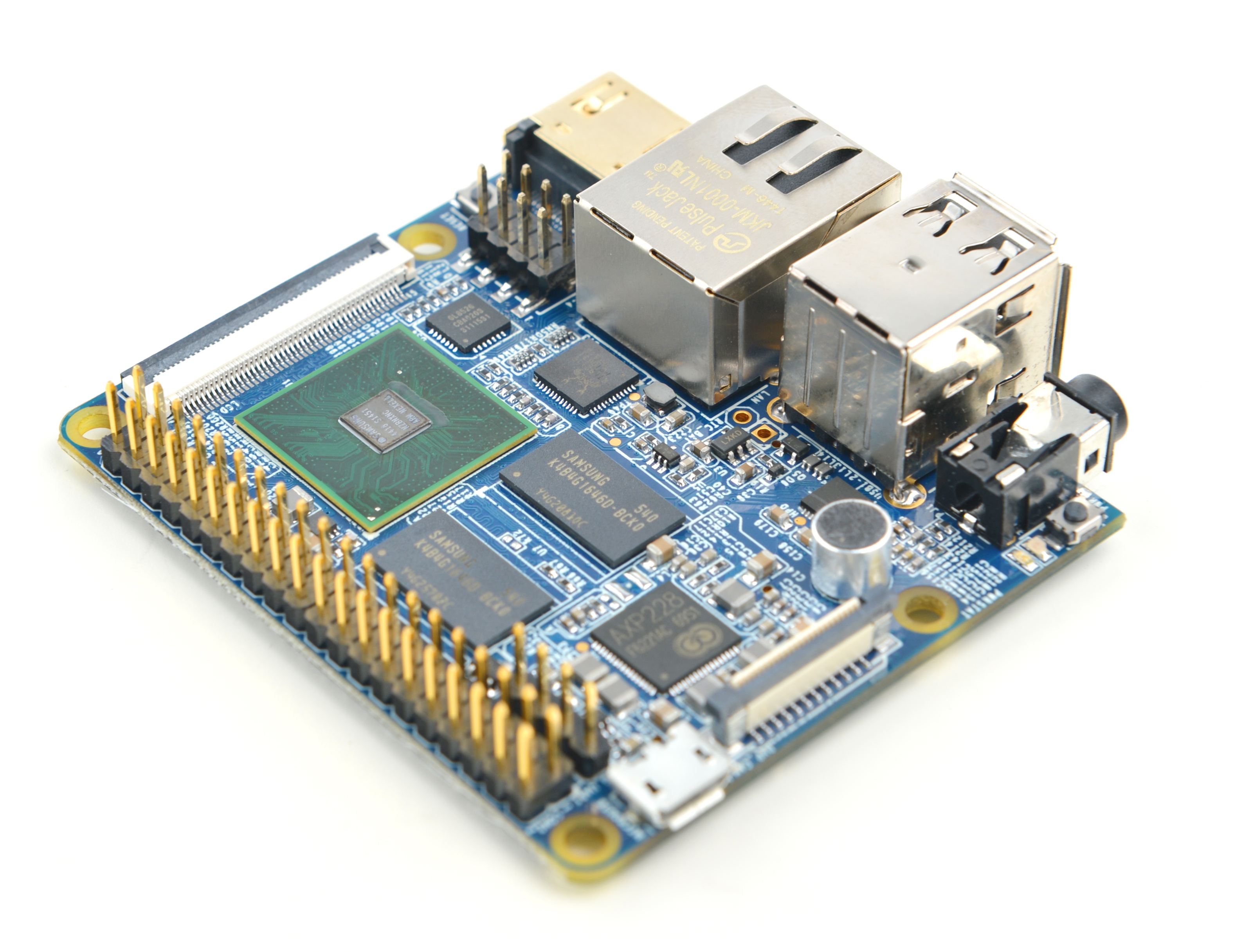
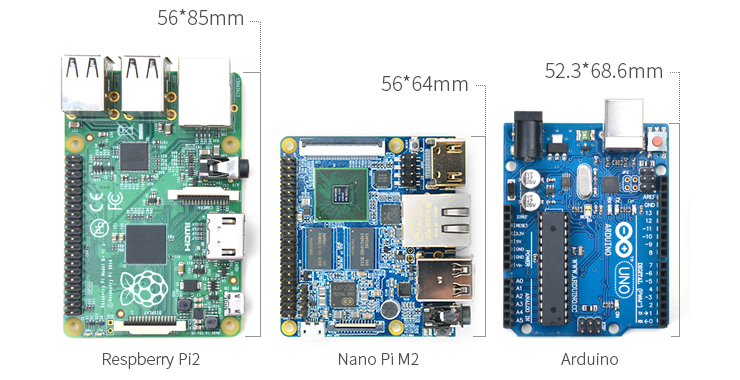
- The NanoPi M2 is another Samsung 4418 based ARM board released by FriendlyARM after the NanoPi 2 and NanoPi 2 Fire. It is only two thirds the size of the Raspberry Pi. It is open source. It works with Ubuntu Core, Ubuntu Mate, Debian, Android 5.1 and etc.
- Compared to the Raspberry Pi 2 the NanoPi M2 uses the Samsung Cortex-A9 S5P4418 Soc. It integrates Gbps Ethernet, AXP228 PMU which supports software power-on/off and wake up functions. It can be powered via the MicroUSB port
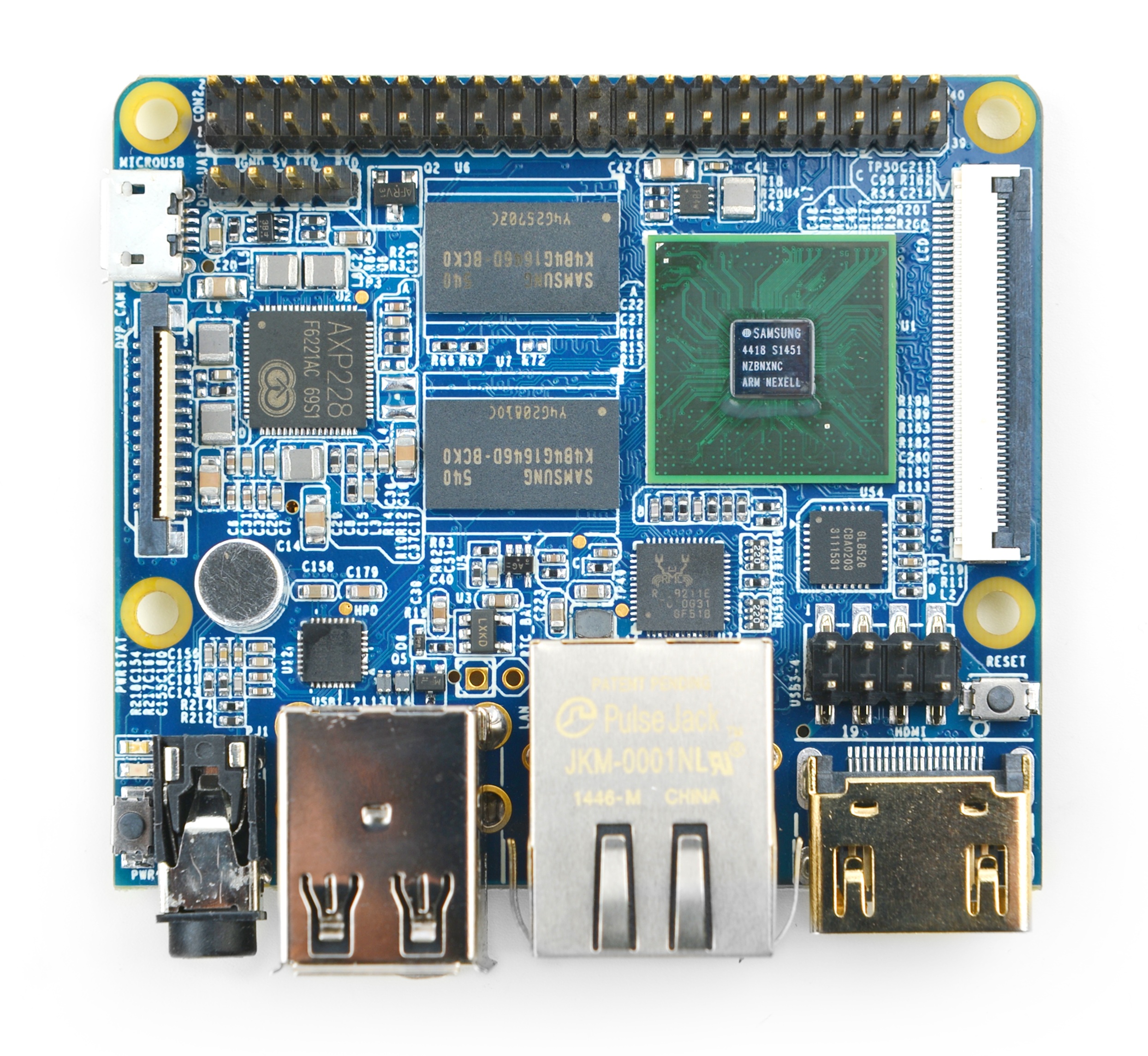
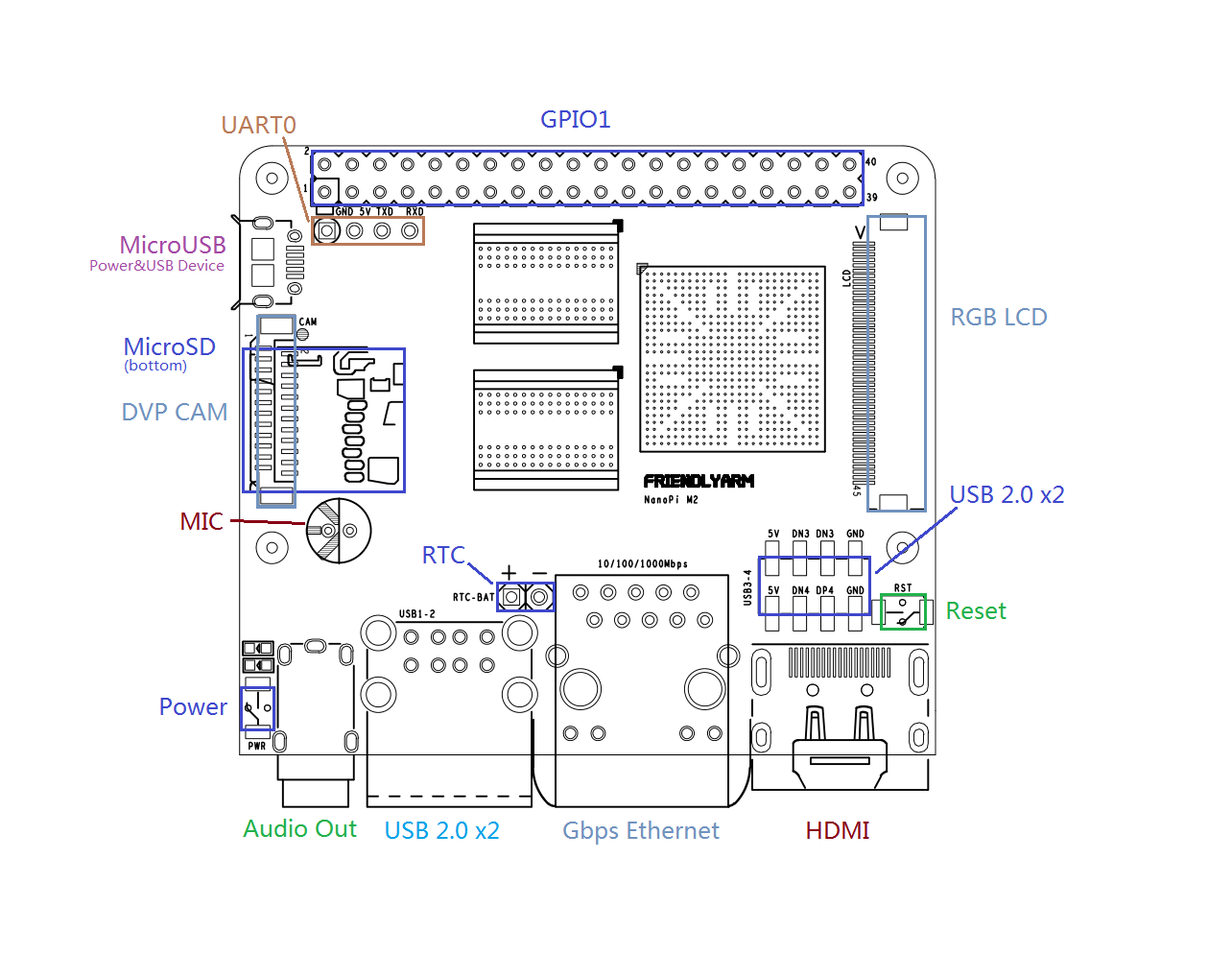
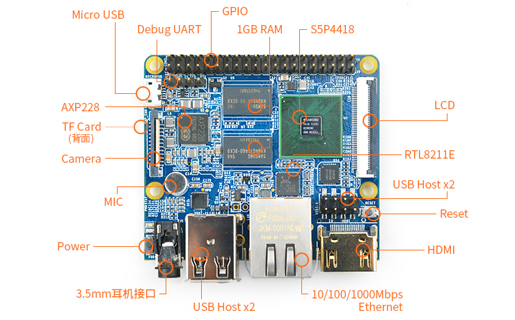
- In such a small board it still integrates rich interfaces and ports. Besides the popular HDMI, 3.5mm audio jack, onboard microphone, four USB hosts and Gbit Ethernet it has a Raspberry Pi compatible 40 pin GPIO pin header and various video interfaces such as a DVP camera interface, an LCD interface which supports I2C capacitive LCD and etc. In addition, for user’s convenience it has a serial debug port for debugging and development.
2 Hardware Spec
- CPU: S5P4418, 400Mhz~1.4GHz
- DDR3 RAM: 32bit 1GB DDR3
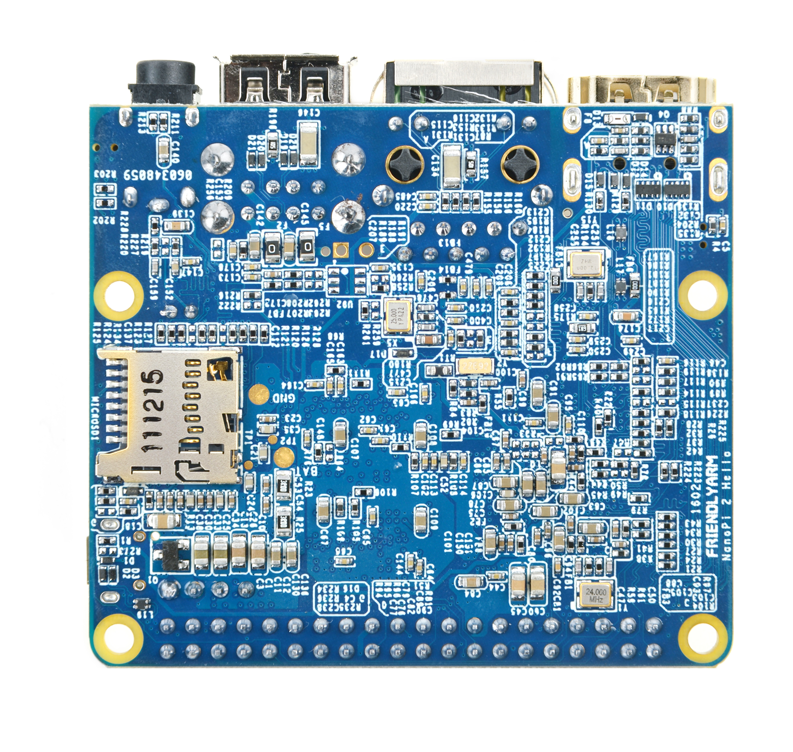
- MicroSD Slot x1
- Connectivity: Gbps Ethernet port(RTL8211E)
- Audio: 3.5mm audio jack/Via HDMI
- Microphone: 1 x onboard Microphone
- USB Host: 4 x USB 2.0 Host, two are standard type A ports and the other two are 2.54mm pitch pin headers
- Micro USB: 1 x USB 2.0 Client
- LCD Interface: 0.5 mm pitch SMT FPC seat, for full-color LCD (RGB: 8-8-8)
- HDMI: HDMI 1.4A, Type-A, 1080P60
- DVP Camera Interface: 0.5mm pitch FPC socket. It includes ITU-R BT 601/656 8-bit, I2C and IO
- GPIO1: 2.54mm pitch 40pin, compatible with Raspberry Pi's GPIO. It includes UART, SPI, I2C, PWM, IO etc
- Debug Serial Port: 4Pin 2.54mm pitch pin header
- User Key: 1 x Power , 1 x Reset
- LED: 1 x Power LED, 1 x System LED
- RTC: RTC Pins
- Power: DC 5V/2A
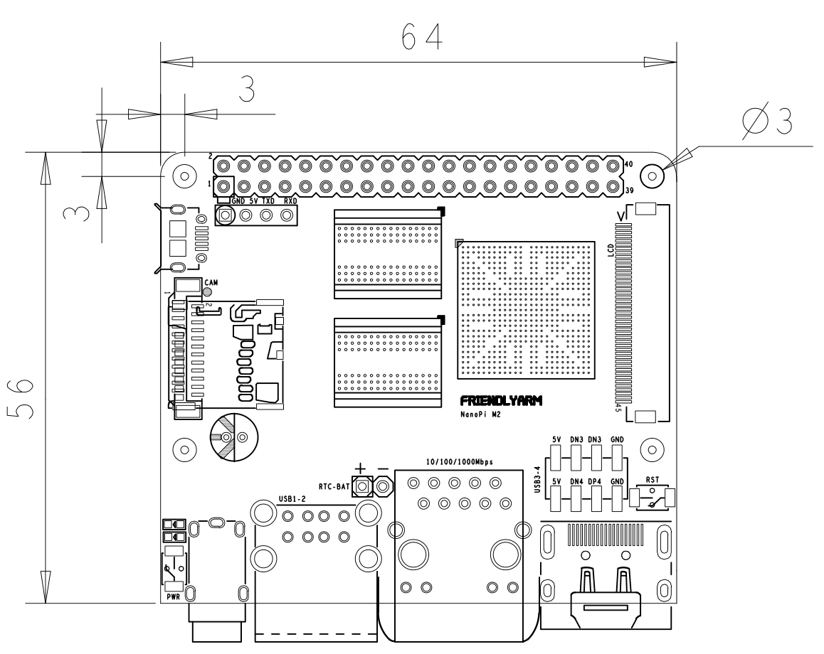
- PCB Dimension(mm): 64 x 56, Six Layer
- Temperature measuring range: -10℃ to 80℃
- OS/Software: u-boot, Android5.1/4.4, Debian Jessie 8
3 Diagram, Layout and Dimension
3.1 Layout
- GPIO1 Pin Spec
Pin# Name Pin# Name 1 SYS_3.3V 2 VDD_5V 3 I2C0_SDA 4 VDD_5V 5 I2C0_SCL 6 DGND 7 GPIOD8/PPM 8 UART3_TXD/GPIOD21 9 DGND 10 UART3_RXD/GPIOD17 11 UART4_TX/GPIOB29 12 GPIOD1/PWM0 13 GPIOB30 14 DGND 15 GPIOB31 16 GPIOC14/PWM2 17 SYS_3.3V 18 GPIOB27 19 SPI0_MOSI/GPIOC31 20 DGND 21 SPI0_MISO/GPIOD0 22 UART4_RX/GPIOB28 23 SPI0_CLK/GPIOC29 24 SPI0_CS/GPIOC30 25 DGND 26 GPIOB26 27 I2C1_SDA 28 I2C1_SCL 29 GPIOC8 30 DGND 31 GPIOC7 32 GPIOC28 33 GPIOC13/PWM1 34 DGND 35 SPI2_MISO/GPIOC11 36 SPI2_CS/GPIOC10 37 AliveGPIO3 38 SPI2_MOSI/GPIOC12 39 DGND 40 SPI2_CLK/GPIOC9
This GPIO pin spec is a little bit different from that of the NanoPi 2. Here is a comparison table of the two:40 pins GPIO comparison table
- Debug Port(UART0)
Pin# Name 1 DGND 2 VDD_5V 3 UART_TXD0 4 UART_RXD0
- DVP Camera IF Pin Spec
Pin# Name 1, 2 SYS_3.3V 7,9,13,15,24 DGND 3 I2C0_SCL 4 I2C0_SDA 5 GPIOB14 6 GPIOB16 8,10 NC 11 VSYNC 12 HREF 14 PCLK 16-23 Data bit7-0
- RGB LCD IF Pin Spec
Pin# Name Description 1, 2 VDD_5V 5V Output, it can be used to power LCD modules 11,20,29, 37,38,39,40, 45 DGND Gound 3-10 Blue LSB to MSB RGB blue 12-19 Green LSB to MSB RGB green 21-28 Red LSB to MSB RGB red 30 GPIOB25 available for users 31 GPIOC15 occupied by FriendlyARM one wire technology to recognize LCD models and control backlight and implement resistive touch, not applicable for users 32 XnRSTOUT Form CPU low when system is reset 33 VDEN signal the external LCD that data is valid on the data bus 34 VSYNC vertical synchronization 35 HSYNC horizontal synchronization 36 LCDCLK LCD clock, Pixel frequency 41 I2C2_SCL I2C2 clock signal, for capacitive touch data transmission 42 I2C2_SDA I2C2 data signal, for capacitive touch data transmission 43 GPIOC16 interrupt pin for capacitive touch, used with I2C2 44 NC not connected
- Note
- SYS_3.3V: 3.3V power output
- VVDD_5V: 5V power input/output. When the external device’s power is greater than the MicroUSB’s the external device is charging the board otherwise the board powers the external device. The input range is 4.7V ~ 5.6V
- All pins are 3.3V, output current is 5mA
- GPIO1's pin spec is a little bit different from that of the NanoPi 2. Refer to this comparison table 40 pins GPIO comparison table
- For more details refer to the document: NanoPi-M2-1602-Schematic.pdf
3.2 Board Dimension
- For more details refer to the document: NanoPi-M2-1602-Dimensions(dxf).zip
4 Get Started
4.1 Essentials You Need
Before starting to use your NanoPi M2 get the following items ready
- NanoPi M2
- microSD Card/TFCard: Class 10 or Above, minimum 8GB SDHC
- microUSB power. A 5V/2A power is a must
- HDMI monitor or LCD
- USB keyboard and mouse
- A host computer running Ubuntu 18.04 64 bit system
4.2 TF Cards We Tested
To make your device boot and run fast we highly recommend you use a Class10 8GB SDHC TF card or a better one. The following cards are what we used in all our test cases presented here:
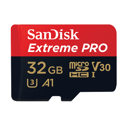
- Sandisk MicroSDHC V30 32GB Extreme Pro (Developer choice)
- SanDisk 32GB High Endurance Video MicroSDHC Card with Adapter for Dash Cam and Home Monitoring Systems (High reliability)
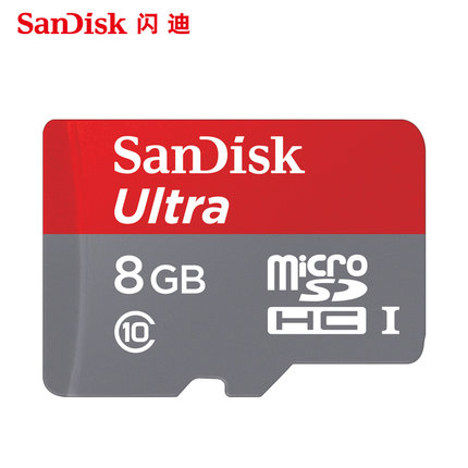
- SanDisk TF 8G Class10 Micro/SD High Speed TF card:
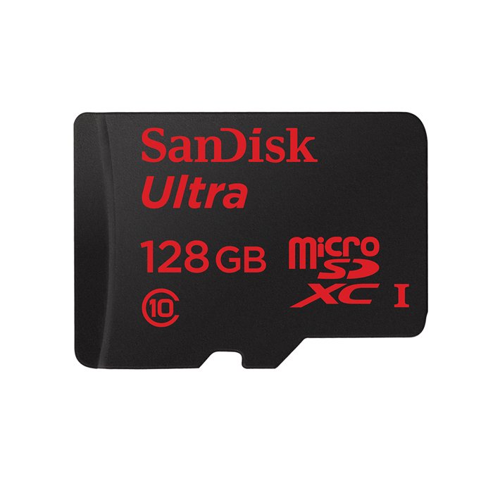
- SanDisk TF128G MicroSDXC TF 128G Class10 48MB/S:
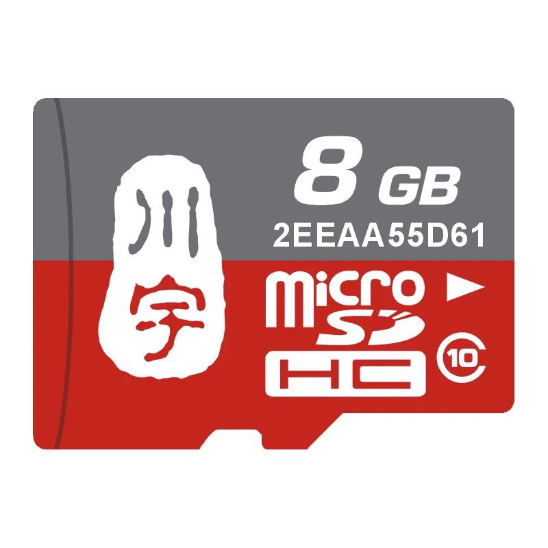
- 川宇 8G C10 High Speed class10 micro SD card:
4.3 Make an Installation MicroSD Card
4.3.1 Under Windows
Get the following files from here:[http://download.friendlyelec.com/nanopim2 to download image files.
- Get a 4G SDHC card and backup its data if necessary.
Image Files s5p4418-debian-sd4g-YYYYMMDD.img.zip Debian image file with X Window s5p4418-debian-wifiap-sd4g-YYYYMMDD.img.zip Debian image file with X Window and WiFi configured as AP s5p4418-kitkat-sd4g-YYYYMMDD.img.zip Android4.4 image file with support for 4G LTE s5p4418-android-sd4g-YYYYMMDD.img.zip Android5.1 image file s5p4418-ubuntu-core-qte-sd4g-YYYYMMDD.img.zip Ubuntu core with Qt Embedded Flash Utility: win32diskimager.rar Windows utility. Under Linux users can use "dd"
- Uncompress these files. Insert an SD card(at least 4G) into a Windows PC and run the win32diskimager utility as administrator. On the utility's main window select your SD card's drive, the wanted image file and click on "write" to start flashing the SD card.
- Insert this card into your NanoPi M2 and power on (with a 5V/2A power source). If the green LED is on and the blue LED is blinking this indicates your NanoPi M2 has successfully booted.
4.3.2 Under Linux Desktop
- 1) Insert your microSD card into your host running Ubuntu and check your SD card's device name
dmesg | tail
Search the messages output by "dmesg" for similar words like "sdc: sdc1 sdc2". If you can find them it means your SD card is recognized as "/dev/sdc". Or you can check that by commanding "cat /proc/partitions"
- 2) Download Flashing Script
git clone https://github.com/friendlyarm/sd-fuse_s5p4418.git
cd sd-fuse_s5p4418
- 3) Flash Android Firmware to MicroSD Card
su
./fusing.sh /dev/sdx
(Note: you need to replace "/dev/sdx" with the device name in your system)
When you do “git clone” you have to hit “Y” within 10 seconds after it prompts you to download image files otherwise you will miss the download.
- 4) Flash Debian Firmware to MicroSD Card
./fusing.sh /dev/sdx debian
4.3.3 Extend NanoPi M2's TF Card Section
- When Debian/Ubuntu is loaded the TF card's section will be automatically extended.
- When Android is loaded you need to run the following commands on your host PC to extend your TF card's section:
sudo umount /dev/sdx?
sudo parted /dev/sdx unit % resizepart 4 100 resizepart 7 100 unit MB print
sudo resize2fs -f /dev/sdx7
(Note: you need to replace "/dev/sdx" with the device name in your system)
4.3.4 LCD/HDMI Resolution
When the system boots our uboot will check whether it is connected to an LCD or to an HDMI monitor. If it recognizes an LCD it will configure its resolution. Our uboot defaults to the HDMI 720P configuration.
If you want to modify the LCD resolution you can modify file "arch/arm/plat-s5p4418/nanopi2/lcds.c" in the kernel and recompile it.
If your NanoPi M2 is connected an HDMI monitor and it runs Android it will automatically set the resolution to an appropriate HDMI mode by checking the "EDID". If your NanoPi M2 is connected an HDMI monitor and it runs Debian by default it will set the resolution to HDMI 720P. If you want to modify the resolution to 1080P modify your kernel's configuration as explained above.
4.4 Update Image Files in MicroSD Card From PC Host
If you want to make some changes to the image files in your MicroSD card follow steps below otherwise you can skip this section.
Insert your MicroSD card into a PC host running Linux, mount the boot and rootfs sections of the SD card and follow the steps below:
1) If you want to change your kernel command line parameters you can do it via the fw_setevn utility under "sd-fuse_s5p4418/tools".
Check the current Command Line:
cd sd-fuse_s5p4418/tools
./fw_printenv /dev/sdc | grep bootargs
Android 5.1.1_r6 starts SELinux. By default it is enforcing. You can change it this way:
./fw_setenv /dev/sdc bootargs XXX androidboot.selinux=permissive
This sets it to "permissive". The "XXX" stands for the original bootargs' value.
2) Update Kernel
Our customized uboot will check the LCD type when it boots.
For a non-Android OS If it recognizes an LCD connected to the NanoPi M2 it will load "uImage" from "boot" otherwise it will load "uImage.hdmi".
For Android it doesn't make any difference which display device is detected. You can use your generated uImage to replace the existing one under "boot".
For Debian if your generated kernel is for an LCD you need to replace the existing uImage or if your kernel is for HDMI you need to replace the existing uImage.hdmi.
4.5 Run Android or Debian
- Insert a MicroSD card with Android/Debian image files into your NanoPi M2, connect the NanoPi M2 to an HDMI monitor and a 5V/2A power source the NanoPi M2 will be automatically powered up. If you can see the blue LED flashing it means your board is working and you will see Android/Debain loading on the HDMI monitor.
1)If you connect the NanoPi M2 to an HDMI monitor you need to use a USB mouse and a USB keyboard to operate. If you connect it to an LCD with capacitive touch you can operate directly on the LCD.
2)If you want to do kernel development you'd better have a serial comms board which will allow you to operate the board via a serial terminal.
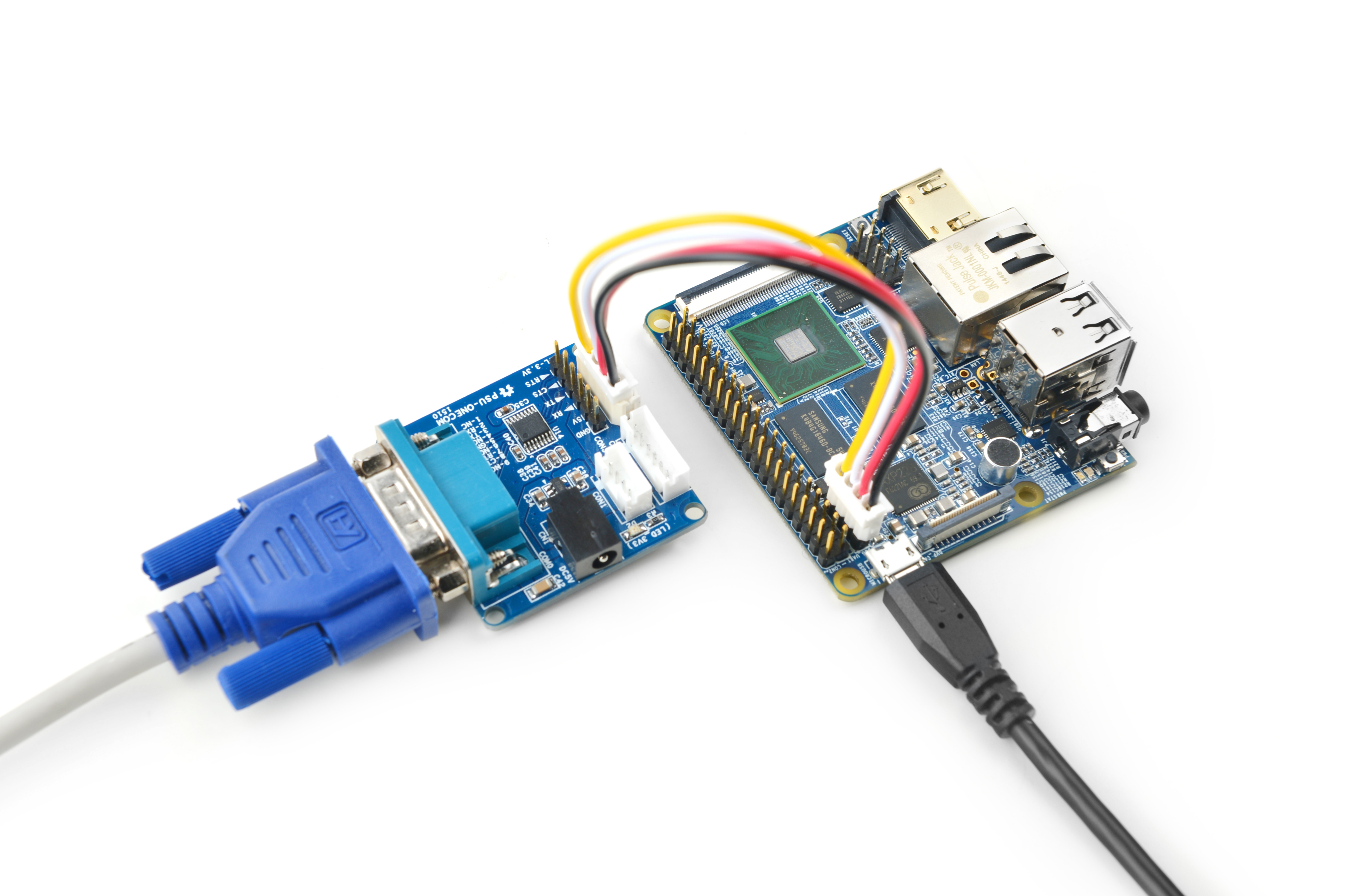
- Here is a setup where we connect a NanoPi M2 to a PC running Ubuntu and Minicom via a serial cable you will see system messages output to the PC’s minicom terminal:
- Under Debian the password for "root" is "fa".
5 Working with Debian
5.1 Ethernet Connection
If the NanoPi M2 is connected to a network via Ethernet before it is powered on it will automatically obtain an IP after it has powered up. If it is not connected via Ethernet or its DHCP is not activated obtaining an IP will fail and system will hang on for about 15 to 60 seconds
- 1) Setup MAC Address
The NanoPi M2 by default doesn't have a valid MAC address. If the board connects a network successfully it will automatically generates a random MAC in "/etc/network/interfaces.d/eth0". Users can change it to a self-defined valid one:
vi /etc/network/interfaces.d/eth0
Here is the content of a sample configuration file:
auto eth0
allow-hotplug eth0
iface eth0 inet dhcp
hwaddress 76:92:d4:85:f3:0f
The "hwaddress" specifies the MAC address. Here the "76:92:d4:85:f3:0f" is a random MAC. We suggest users change it to a valid one.
Note: when you reset the MAC make sure your MAC meets IEEE's definition otherwise it will cause unexpected issues.
After you make your change, save, exit and reboot your board or run the following commands to restart the network:
systemctl restart networking
5.2 Install Debian Packages
We provide a Debian Jessie image. You can install Jessie's packages by commanding "apt-get". If this is your first installation you need to update the package list by running the following command:
apt-get updateYou can install your preferred packages. For example if you want to install an FTP server you can do this:
apt-get install vsftpdNote: you can change your download server by editting "/etc/apt/sources.list". You can get a complete server list from [1]. You need to select the one with "armhf".
5.3 HDMI Audio Output/3.5mm Audio Jack Output Under Debian
By default our Debian system's HDMI output doesn't have audio output. To enable the HDMI audio output you need to install the alsa packages
Firstly, make sure your board runs our latest Debian image and is connected to the internet:
After your board is powered up run the following commands:
apt-get update
apt-get install libasound2
apt-get install alsa-base
apt-get install alsa-utils
After the installation is done copy a ".wav" audio file to your NanoPi M2, connect your NanoPi M2 to an HDMI monitor and play it by using the following command:
aplay music.wavOur Debian system's default audio output is the 3.5mm audio jack. You can turn on the HDMI audio by editting the /etc/asound.conf file:
pcm.!default {
    type hw
    card 1
    device 0
}

ctl.!default {
    type hw
    card 1
}
card 0 points to the 3.5mm audio jack and card 1 points to the HDMI audio. You need to save your changes and reboot your system to make your changes take effect.
6 Make Your Own OS Image
6.1 Setup Development Environment
Install Cross Compiler:
git clone https://github.com/friendlyarm/prebuilts.git -b master --depth 1
cd prebuilts/gcc-x64
cat toolchain-4.9.3-armhf.tar.gz* | sudo tar xz -C /
Then add the compiler's directory to "PATH" by appending the following lines in "~/.bashrc":
export PATH=/opt/FriendlyARM/toolchain/4.9.3/bin:$PATH
export GCC_COLORS=auto
Execute "~/.bashrc" to make the changes into effect. Note that there is a space after the first ".":
. ~/.bashrcThis compiler is a 64-bit one therefore it cannot be run on a 32-bit Linux. After the compiler is installed you can verify it by running the following commands:
arm-linux-gcc -v
Using built-in specs.
COLLECT_GCC=arm-linux-gcc
COLLECT_LTO_WRAPPER=/opt/FriendlyARM/toolchain/4.9.3/libexec/gcc/arm-cortexa9-linux-gnueabihf/4.9.3/lto-wrapper
Target: arm-cortexa9-linux-gnueabihf
Configured with: /work/toolchain/build/src/gcc-4.9.3/configure --build=x86_64-build_pc-linux-gnu
--host=x86_64-build_pc-linux-gnu --target=arm-cortexa9-linux-gnueabihf --prefix=/opt/FriendlyARM/toolchain/4.9.3
--with-sysroot=/opt/FriendlyARM/toolchain/4.9.3/arm-cortexa9-linux-gnueabihf/sys-root --enable-languages=c,c++
--with-arch=armv7-a --with-tune=cortex-a9 --with-fpu=vfpv3 --with-float=hard
...
Thread model: posix
gcc version 4.9.3 (ctng-1.21.0-229g-FA)
6.2 Compile U-Boot
Download the U-Boot source code and compile it. Note that the github's branch is nanopi2-lollipop-mr1:
git clone https://github.com/friendlyarm/uboot_nanopi2.git
cd uboot_nanopi2
git checkout nanopi2-lollipop-mr1
make s5p4418_nanopi2_config
make CROSS_COMPILE=arm-linux-
After your compilation succeeds a u-boot.bin will be generated. If you want to test it flash it to your installation MicroSD card via fastboot. Here is how you can do it:
1) On your PC host run "sudo apt-get install android-tools-fastboot" to install the fastboot utility;
2) Connect your NanoPi M2 to your PC host via a serial cable (e.g. PSU-ONECOME). Press the enter key within two seconds right after you power on your NanoPi M2 and you will enter uboot's command line mode;
3) After type in "fastboot" and press "enter" you will enter the fastboot mode;
4) Connect your NanoPi M2 to this PC host via a microUSB cable and type in the following command to flash the u-boot.bin:
fastboot flash bootloader u-boot.bin
Warning: you cannot update this MicroSD card by commanding "dd". This command will cause trouble when booting the NanoPi M2.
6.3 Prepare mkimage
You need the mkimage utility to compile a U-Boot source code package. Make sure this utility works well on your host before you start compiling a uImage.
You can install this utility by either commanding "sudo apt-get install u-boot-tools" or following the commands below:
cd uboot_nanopi2
make CROSS_COMPILE=arm-linux- tools
sudo mkdir -p /usr/local/sbin && sudo cp -v tools/mkimage /usr/local/sbin
6.4 Compile Linux kernel
6.4.1 Compile Kernel
- Download Kernel Source Code
git clone https://github.com/friendlyarm/linux-3.4.y.git
cd linux-3.4.y
git checkout nanopi2-lollipop-mr1
The NanoPi M2's kernel source code lies in the "nanopi2-lollipop-mr1" branch.
- Compile Android Kernel
make nanopi2_android_defconfig
touch .scmversion
make uImage
- Compile Debian Kernel
make nanopi2_linux_defconfig
touch .scmversion
make uImage
After your compilation succeeds a uImage will be generated in the "arch/arm/boot/uImage" directory. This kernel is for HDMI 720P. You can use it to replace the existing uImage.hdmi
If you want to generate a kernel for HDMI 1080P you can do it this way:
touch .scmversion
make nanopi2_linux_defconfig
make menuconfig
  Device Drivers -->
    Graphics support -->
      Nexell Graphics -->
        [ ] LCD
        [*] HDMI
        (0)   Display In  [0=Display 0, 1=Display 1]
              Resolution (1920 * 1080p)  --->
make uImage
After your compilation succeeds a uImage will be generated for HDMI 1080P. You can use it to replace the existing uImage.
If you want to generate a kernel for LCD you can do it this way:
touch .scmversion
make nanopi2_linux_defconfig
make menuconfig
  Device Drivers -->
    Graphics support -->
      Nexell Graphics -->
        [*] LCD
        [ ] HDMI
make uImage
After your compilation succeeds a uImage will be generated for LCD. You can use it to replace the existing uImage.
6.4.2 Compile Kernel Modules
Android contains kernel modules which are in the "/lib/modules" directory in the system section. If you want to add your own modules to the kernel or you changed your kernel configurations you need to recompile these new modules.
Compile Original Kernel Modules:
cd linux-3.4.y
make CROSS_COMPILE=arm-linux- modules
Here we have two new modules and we can compile them by following the commands below:
cd /opt/FriendlyARM/s5p4418/android
./vendor/friendly-arm/build/common/build-modules.sh
The "/opt/FriendlyARM/s5p4418/android" directory points to the top directory of Android source code. You can get more details by specifying option "-h".
After your compilation succeeds new modules will be generated
6.5 Compile Android
- Install Cross Compiler
Installing 64 bit Ubuntu 16.04 on your PC host.
sudo apt-get install bison g++-multilib git gperf libxml2-utils make python-networkx zip
sudo apt-get install flex libncurses5-dev zlib1g-dev gawk minicom
For more details refer to https://source.android.com/source/initializing.html 。
- Download Source Code(Android 5.1)
You need to use repo to get the Android source code. Refer to https://source.android.com/source/downloading.html 。
mkdir android && cd android
repo init -u https://github.com/friendlyarm/android_manifest.git -b nanopi2-lollipop-mr1
repo sync
The "android" directory is the working directory.
If you want to try Android4.4's source code you can run the following commands:
mkdir android && cd android
repo init -u https://github.com/friendlyarm/android_manifest.git -b nanopi2-kitkat
repo sync
Option "-b" specifies a branch
- Compile System Package
source build/envsetup.sh
lunch aosp_nanopi2-userdebug
make -j8
After your compilation succeeds the following files will be generated in the "out/target/product/nanopi2/" directory.
filename partition Description boot.img boot - cache.img cache - userdata.img userdata - system.img system - partmap.txt - partition description file
- Flash Image to TF Card
If you want to boot your board from a TF card you can copy your generated image files to your card's sd-fuse_s5p4418/android/ direcroty and flash the image to the card with our script. For more details refer to #Under Linux Desktop.
7 Connect NanoPi M2 to External Modules
7.1 Connect NanoPi M2 to USB Camera(FA-CAM202)
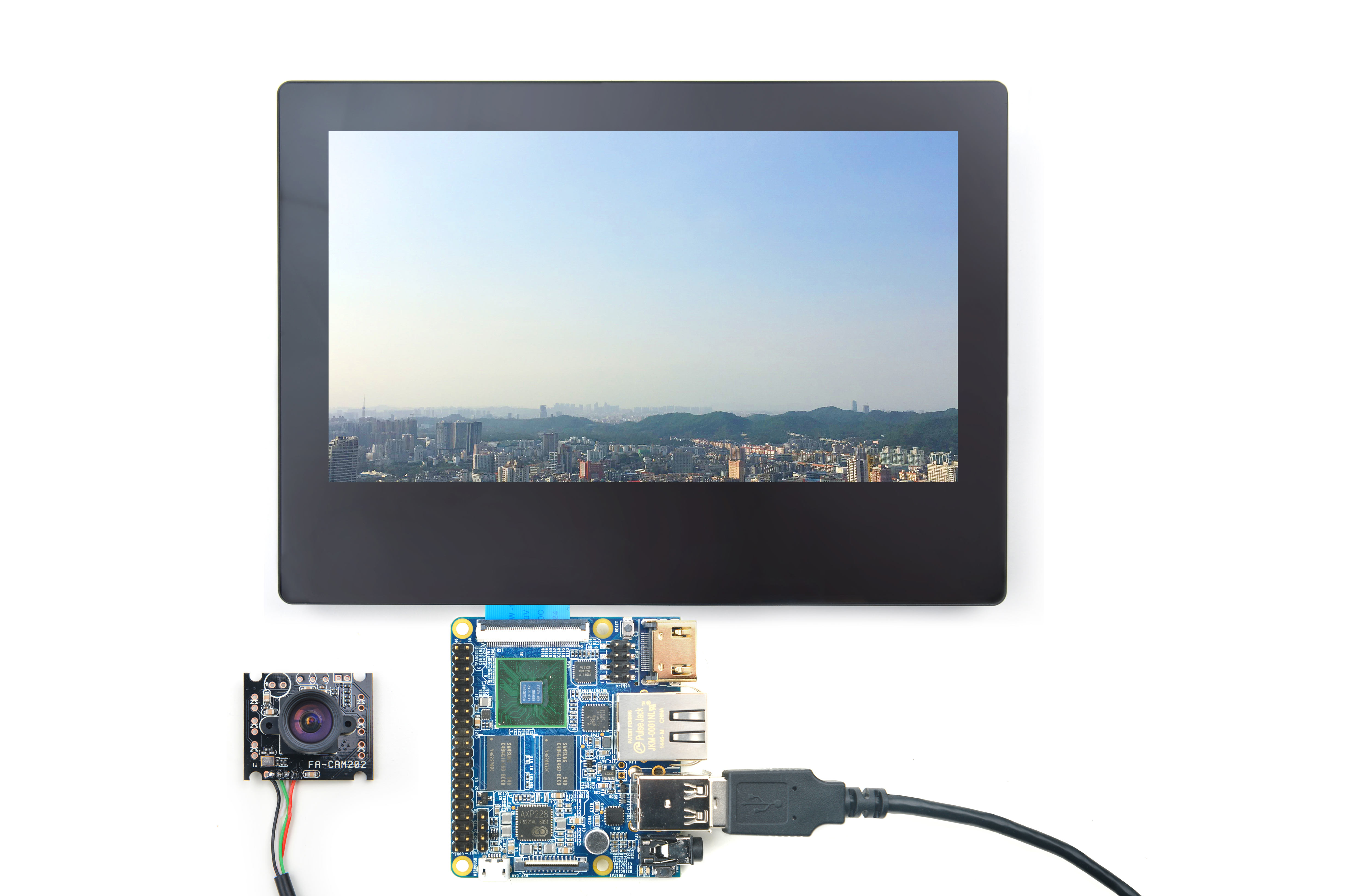
- In this use case the NanoPi M2 runs Debian. If you connect your NanoPi M2 to our LCD or an HDMI monitor after Debain is fully loaded click on "other"-->"xawtv" on the left bottom of the GUI and the USB Camera application will be started. After enter "welcome to xawtv!" click on "OK" to start exploring.
7.2 Connect NanoPi M2 to CMOS 5M-Pixel Camera
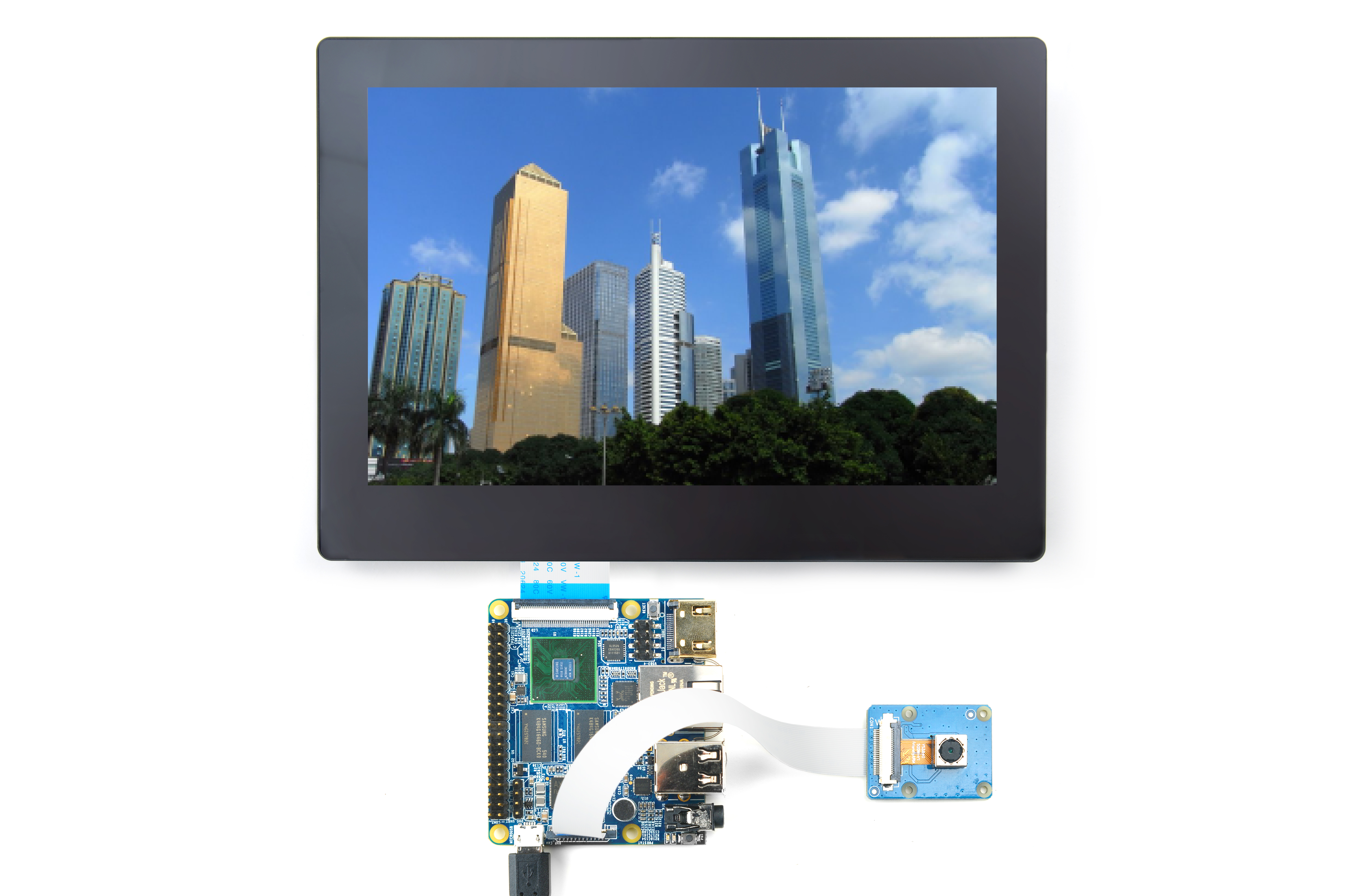
For more details about the CAM500B camera refer to [1]
- If your NanoPi M2 runs Android5.1 and it is connected to our LCD or an HDMI monitor after Android is fully loaded click on the "Camera" icon and the application will be started. You can take pictures or record videos
- Under Debian/Ubuntu a camera utility "nanocams" is available for previewing 40 frames and picture taking. You can try it by following the commands below
sudo nanocams -p 1 -n 40 -c 4 -o IMG001.jpg
For more details about the usage of the nanocams run "nanocams -h". You can get its source code from our git hub:
git clone https://github.com/friendlyarm/nexell_linux_platform.git
7.3 Use OpenCV to Access USB Camera
- The full name of "OpenCV" is Open Source Computer Vision Library and it is a cross platform vision library.
- When the NanoPi M2 runs Debian users can use OpenCV APIs to access a USB Camera device.
1. Here is a guideline on how to use OpenCV with C++ on the NanoPi M2:
- Firstly you need to make sure your NanoPi M2 is connected to the internet.Login to your NanoPi M2 via a serial terminal or SSH. After login type in your username(root) and password(fa):
- Run the following commands:
apt-get update
apt-get install libcv-dev libopencv-dev
2. Make sure your USB camera works with the NanoPi M2. You can test your camera with NanoPi M2's camera utility.
3. Check your camera device:
ls /dev/video*
- Note:in our case "video0" was the camera's device name.
4. OpenCV's code sample(Official Code Sample in C++) under /home/fa/Documents/opencv-demo. You can compile it by running the following command:
cd /home/fa/Documents/opencv-demo
make
If it is compiled successfully a demo executable will be generated
5. Connect NanoPi M2 to a USB Keyboard & Run the Following Command:
./demo7.4 Connect NanoPi M2 to USB WiFi
Our system has support for popular USB WiFi drivers. Many USB WiFi modules are plug and play with our system. Here is a list of models we tested;
Number Model 1 RTL8188CUS/8188EU 802.11n WLAN Adapter 2 RT2070 Wireless Adapter 3 RT2870/RT3070 Wireless Adapter 4 RTL8192CU Wireless Adapter 5 MI WiFi mt7601
If you NanoPi M2 is connected to a USB WiFi and is powered up you can log into M2 and run the following command to check if the USB WiFi is recognized. If "wlan0" is listed it indicates your USB WiFi has been recognized:
ifconfig -a
Open the /etc/wpa_supplicant/wpa_supplicant.conf file and append the following lines:
network={
        ssid="YourWiFiESSID"
        psk="YourWiFiPassword"
}
The "YourWiFiESSID" and "YourWiFiPassword" need to be replaced with your actual ESSID and password.
Save, exit and run the following commands to connect to your WiFi router:
ifdown wlan0
ifup wlan0
If your WiFi password has special characters or you don't want your password saved as plain text you can use "wpa_passphrase" to generate a psk for your WiFi password. Here is how you can do it:
wpa_passphrase YourWiFiESSID
Following the prompt type in your password and you will get a new password in the /etc/wpa_supplicant/wpa_supplicant.conf file. Now you can replace the existing password in the wlan0 file with the new one.
- Click on here to enter the kernel compilation [2]
7.5 Connect NanoPi M2 to Matrix GPS Module
- The Matrix-GPS module is a small GPS module with high performance. It can be used in navigation devices, four-axle drones and etc.
- The Matrix-GPS module uses serial communication. When the NanoPi M2 is connected to the Matrix GPS module, after the NanoPi M2 is powered up type in the following command in a terminal or click on the xgps icon it will be started.
$su - fa -c "DISPLAY=:0 xgps 127.0.0.1:9999"
- Or on the Debian GUI start the LXTerminal, type in "xgps" and enter it will be started too.
For more details about this GPS module refer to this link
Refer to the following diagram to connect the NanoPi M2 to the Matrix-GPS:
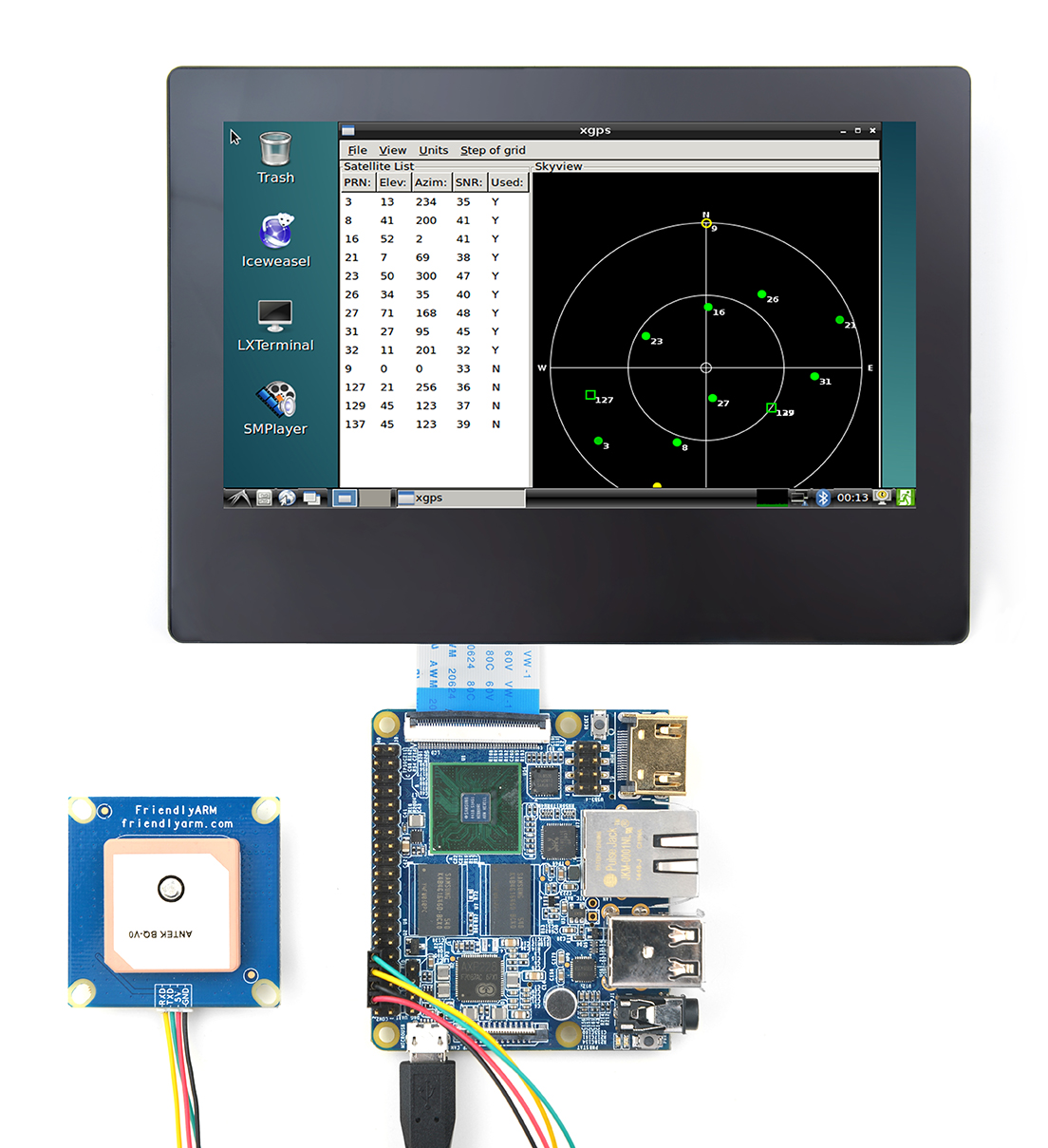
Connection Details:
| Matrix-GPS | NanoPi M2 |
| RXD | Pin8 |
| TXD | Pin10 |
| 5V | Pin4 |
| GND | Pin6 |
7.6 Connect NanoPi M2 to I2C Device
- The Matrix-I2C_LCD1602_Keypad module is an easy-to-use display module based on the LCD1602. This module integrates the LCD1602 and the MCP23017 module. It has five programmable keys which allow users to control the LCD1602's display and external devices connected to the module.
- The MCP23017 communicates through I2C interface. You can learn how the NanoPi M2 communicates to an I2C device by studying this module.
For more details about the Matrix - I2C LCD1602 Keypad refer to this link
Refer to the following diagram to connect the NanoPi M2 to the Matrix-I2C_LCD1602_Keypad:
matrix-i2c_lcd1602_keypad_nanopi_M2
Connection Details:
| Matrix-I2C_LCD1602_Keypad | NanoPi M2 |
| SDA | Pin3 |
| SCL | Pin5 |
| 5V | Pin4 |
| GND | Pin6 |
7.7 Connect NanoPi M2 to SPI Device
- The Matrix-2'8_SPI_Key_TFT module is a 2.8" TFT LCD module. It uses the ST7789S IC and the XPT2046 resistive IC. The LCD's resolution is 320 * 240 and communicates via SPI. It has three programmable user keys.
For more details about the Matrix-2'8_SPI_Key_TFT SPI module refer to this link
Refer to the following diagram to connect the NanoPi M2 to the Matrix-2'8_SPI_Key_TFT module:
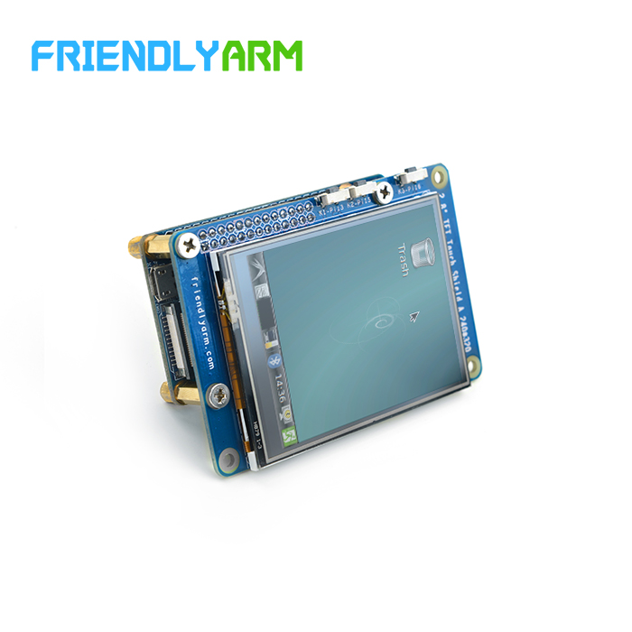
Connection Details
| Matrix-2'8_SPI_Key_TFT | NanoPi M2 |
| GND | Pin6 |
| 5V | Pin2 |
| LED_EN | Pin11 |
| LCD_RESET | Pin7 |
| LCD_D/C | Pin22 |
| LCD_CS | Pin24 |
| SPICLK | Pin23 |
| SPIMOSI | Pin19 |
| SPIMISO | Pin21 |
| T_CS | Pin26 |
| T_IRQ | Pin18 |
8 Android Hardware Access
FriendlyElec developed a library called “libfriendlyarm-things.so”, for android developer to access the hardware resources on the development board in their android apps, the library is based on Android NDK.
Accessible Modules:
- Serial Port
- PWM
- EEPROM
- ADC
- LED
- LCD 1602 (I2C)
- OLED (SPI)
Accessible Ports:
- GPIO
- Serial Port
- I2C
- SPI
Please refer to the following url for details:
- Homepage: http://wiki.friendlyelec.com/wiki/index.php/FriendlyThings
- Examples: https://github.com/friendlyarm/friendlythings-examples
- Guide to API: http://wiki.friendlyelec.com/wiki/index.php/FriendlyThings_APIs
9 More OS Support
9.1 DietPi

DietPi is a highly optimised & minimal Debian-based Linux distribution. DietPi is extremely lightweight at its core, and also extremely easy to install and use.
Setting up a single board computer (SBC) or even a computer, for both regular or server use, takes time and skill. DietPi provides an easy way to install and run favourite software you choose.
For more information, please visit this link https://dietpi.com/docs/.
DietPi supports many of the NanoPi board series, you may download the image file from here:
9.2 FriendlyCore
Ubuntu Core with Qt-Embedded is a light Linux system without X-windows. It uses the Qt-Embedded's GUI and is popular in industrial and enterprise applications. Besides the regular Ubuntu core's features our Ubuntu-Core has the following additional features:
- it supports our LCDs with both capacitive touch and resistive touch(S700, X710, S70)
- it supports WiFi
- it supports Ethernet
- it supports Bluetooth and has been installed with bluez utilities
- it supports audio playing
For more details refer to Ubuntu Core with Qt-Embedded.
10 Source Code and Image Files Download Links
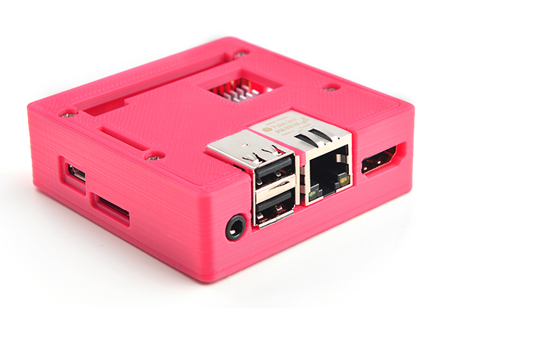
11 3D Housing Printing Files
- NanoPi M2 3D Housing Printing Files: [5]
12 Resources
- 《创客秘籍》Hacker's Book in Chinese by FriendlyARM
- 《创客秘籍-02》Hacker's Book-02 in Chinese by FriendlyARM
- 《创客秘籍-03》Hacker's Book-03 in Chinese by FriendlyARM
- Schematic (NanoPi-M2-1602-Schematic.pdf)
- Dimensional Diagram (NanoPi-M2-1602-Dimensions(dxf).zip)
- S5P4418 Datasheet (S5P4418_Datasheet_0.1.pdf)
- Matrix Modules & Wiki Sites:
- Button
- LED
- A/D Converter
- Relay
- 3-Axis Digital Accelerometer
- 3-Axis Digital Compass
- Temperature Sensor
- Temperature & Humidity Sensor
- Buzzer
- Joystick
- I2C(PCF8574)+LCD1602
- Sound Sensor
- Ultrasonic Ranger
- GPS
- Matrix - Compact Kit
- Fire Sensor
- CAM500A Camera
- BAll Rolling Switch
- 2'8 SPI Key TFT 2.8" SPI LCD
- IR Counter
- IR Receiver
- L298N Motor Driver
- MQ-2 Gas Sensor
- MQ-3 Gas Sensor
- One_Touch_Sensor
- _Photoresistor
- _Potentiometer
- Pressure & Temperature Sensor
- RGB LED
- RTC
- Rotary Encoder
- Soil Moisture Sensor
- Thermistor
- USB WiFi
- Water Sensor
13 Tech Support
If you have any further questions please visit our forum[6] and post a message or email us at techsupport@friendlyarm.com. We will endeavor to get back to you as soon as possible.
14 Update Log
14.1 March-01-2016
- Released English Version
14.2 March-03-2016
- Modified section 2
14.3 March-04-2016
- added section 10
14.4 March-07-2016
- rewrote section 1
14.5 March-17-2016
- Updated Kali and Ubuntu-Mate download links
14.6 March-18-2016
- Modified section 4.3.1
14.7 March-27-2016
- Corrected expression errors
14.8 April-08-2016
- Added sections 5.3, 7.5, 7.6, 7.7
- Updated sections 8.1 and 11
14.9 July-05-2016
- Rewrote section 4.3.3 and 6.5
14.10 Nov-03-2016
- Updated sections 4.3.1, 7.2 and 7.4
14.11 Dec-07-2016
- Updated sections 6.5
