Difference between revisions of "NanoPC-T4"
(→Flash Image under Windows with Type-C Cable) |
(→Flash Image to eMMC under Linux with Type-C Cable) |
||
| Line 620: | Line 620: | ||
</syntaxhighlight> | </syntaxhighlight> | ||
| − | If the image's MiniLoaderAll.bin has a different version or the image you want to flash to eMMC is different from the image that already exists in eMMC you need to | + | If the image's MiniLoaderAll.bin has a different version or the image you want to flash to eMMC is different from the image that already exists in eMMC you need to erase eMMC and then flash your new image to it.<br /> |
| − | Boot your board and enter the LOADER mode, run the following commands to | + | Boot your board and enter the LOADER mode, run the following commands to erase eMMC. If a prompt shows "Download Boot Start" and it lasts for 10 seconds you need to press the Reset button and run the following commands again. |
<syntaxhighlight lang="bash"> | <syntaxhighlight lang="bash"> | ||
sudo upgrade_tool EF MiniLoaderAll.bin | sudo upgrade_tool EF MiniLoaderAll.bin | ||
Revision as of 07:31, 15 August 2018
Contents
- 1 Introduction
- 2 Hardware Spec
- 3 Software Features
- 4 Diagram, Layout and Dimension
- 5 Get Started
- 6 Work with Android7
- 7 Work with FriendlyCore
- 7.1 Introduction
- 7.2 System Login
- 7.3 Configure System with npi-config
- 7.4 Develop Qt Application
- 7.5 Setup Program to AutoRun
- 7.6 Extend TF Card's Section
- 7.7 Transfer files using Bluetooth
- 7.8 WiFi
- 7.9 Ethernet Connection
- 7.10 WiringPi and Python Wrapper
- 7.11 Custom welcome message
- 7.12 Modify timezone
- 7.13 Select the system default audio device
- 7.14 Change the behavior of the PWM fan
- 8 Work with Lubuntu
- 9 Make Your Own OS Image
- 10 More OS Support
- 11 Link to Rockchip Resources
- 12 Schematic, PCB CAD File
- 13 Update Log
1 Introduction


- The NanoPC-T4 is by far the smallest RK3399 based high-performance ARM board with popular ports and interfaces. Its software is fully open source. It is as small as 100 x 64 mm. It has 4GB LPDDR3 RAM, 16GB eMMC flash, onboard 2.4G & 5G dual-band WiFi module and a full standard M.2 PCIe interface which supports an NVME SSD high-speed hard drive. The NanoPC-T4 supports GPU and VPU acceleration and works with Android 7.1 and Lubuntu Desktop.
- The NanoPC-T4 has a MIPI-CSI dual camera interface, a MIPI-DSI and an eDP display interfaces, and an HDMI 2.0 interface. It has Type-C/DP, USB 3.0, USB2.0, MicroSD, Gbps Ethernet port, 3.5mm audio jack, infrared receiver, AD input, serial debug interface and a 40Pin RPi compatible connector.
- The RK3399 SoC has an internal Mali-T860 GPU which has powerful capabilities of processing 3D and HD H.265/H2.64 video streams. It supports dual camera inputs, dual ISP interface capable of doing image processing up to 13MPix/s. The NanoPC-T4 is a perfect platform for AI and deep learning applications. It can be widely used in advertisement machines, game machines, video conference applications, surveillance systems, clusters, VR/AR applications, machine vision applications and etc.
2 Hardware Spec
- SoC: Rockchip RK3399
- CPU: big.LITTLE,Dual-Core Cortex-A72(up to 2.0GHz) + Quad-Core Cortex-A53(up to 1.5GHz)
- GPU: Mali-T864 GPU,supports OpenGL ES1.1/2.0/3.0/3.1, OpenVG1.1, OpenCL, DX11, and AFBC
- VPU: 4K VP9 and 4K 10bits H265/H264 60fps decoding, Dual VOP, etc
- PMU: RK808-D PMIC, cooperated with independent DC/DC, enabling DVFS, solfware power-down, RTC wake-up, system sleep mode
- RAM: Dual-Channel 4GB LPDDR3-1866
- Flash: 16GB eMMC 5.1 Flash
- Ethernet: Native Gigabit Ethernet
- Wi-Fi/BT: 802.11a/b/g/n/ac, Bluetooth 4.1, Wi-Fi and Bluetooth combo module, dual antenna interface
- Video Input: one or two 4-Lane MIPI-CSI, dual ISP, up to 13MPix/s,supports simultaneous input of dual camera data
- Video output
- HDMI: HDMI 2.0a, supports 4K@60Hz,HDCP 1.4/2.2
- DP on Type-C: DisplayPort 1.2 Alt Mode on USB Type-C
- LCD Interface: one eDP 1.3(4-Lane,10.8Gbps), one or two 4-Lane MIPI-DSI
- Audio Out: 3.5mm Dual channel headphone jack, or HDMI
- Audio In: Onboard microphone
- USB 2.0: 2 independent native USB 2.0 Host A interfaces
- USB 3.0: 1 native USB 3.0 Host A type interface
- USB Type-C: Supports USB3.0 Type-C and DisplayPort 1.2 Alt Mode on USB Type-C
- PCIe: One M.2 M-Key PCIe x4 socket, compatible with PCIe 2.1, Dual operation mode; Onboard M3 PCB nut for mounting M.2 2280 module
- microSD Slot x 1
- 40Pin GPIO Extension ports:
- 3 X 3V/1.8V I2C, up to 1 x 3V UART, 1 X 3V SPI, 1 x SPDIF_TX, up to 8 x 3V GPIOs
- 1 x 1.8V I2S, 3 x 1.8V GPIOs
- ADC: 3 x 1.8V ADC inputs, 5 Pin 2.54mm header
- Debug: one Debug UART, 4 Pin 2.54mm header, 3V level, 1500000bps
- Keys: PowerKey, Reset, MASKROM(BOOT), Recovery
- LED: 1 x power LED and 1 x GPIO Controlled LED
- IR reciver: Onboard IR reciver, Acceptes 38KHz carrier frequency
- RTC Battery: 2 Pin 1.27/1.25mm RTC battery input connector
- Cooling: two 2.5mm PCB nuts for mounting heat sink; 3 Pin 12V cooling fan interface with PWM
- Power supply: DC 12V/2A
- PCB: Ten Layer, 100 mm x 64 mm
- Ambient Operating Temperature: 0℃ to 80℃
3 Software Features
4 Diagram, Layout and Dimension
4.1 Layout

- 40 Pin GPIO Pin Spec
Pin# Assignment Pin# Assignment 1 VCC3V3_SYS 2 VCC5V0_SYS 3 I2C2_SDA(3V) 4 VCC5V0_SYS 5 I2C2_SCL(3V) 6 GND 7 GPIO1_A0(3V) 8 GPIO4_C1/I2C3_SCL(3V) 9 GND 10 GPIO4_C0/I2C3_SDA(3V) 11 GPIO1_A1(3V) 12 GPIO1_C2(3V) 13 GPIO1_A3(3V) 14 GND 15 GPIO1_A4(3V) 16 GPIO1_C6(3V) 17 VCC3V3_SYS 18 GPIO1_C7(3V) 19 SPI1_TXD/UART4_TX(3V) 20 GND 21 SPI1_RXD/UART4_RX(3V) 22 GPIO1_D0(3V) 23 SPI1_CLK(3V) 24 SPI1_CSn0(3V) 25 GND 26 GPIO4_C5/SPDIF_TX(3V) 27 I2C2_SDA(1.8V) 28 I2C2_SCL(1.8V) 29 I2S1_LRCK_RX(1.8V) 30 GND 31 I2S1_LRCK_TX(1.8V) 32 I2S_CLK(1.8V) 33 I2S1_SCLK(1.8V) 34 GND 35 I2S1_SDI0(1.8V) 36 I2S1_SDO0(1.8V) 37 GPIO3_D4(1.8V) 38 GPIO3_D5(1.8V) 39 GND 40 GPIO3_D6(1.8V)
- eDP Interface Pin Spec
- Connector P/N: I-PEX-20455-030E
Pin# Assignment Description 1 GND Signal ground 2 EDP_TX3N eDP data lane 3 negative output 3 EDP_TX3P eDP data lane 3 positive output 4 GND Signal ground 5 EDP_TX2N eDP data lane 2 negative output 6 EDP_TX2P eDP data lane 2 positive output 7 GND Signal ground 8 EDP_TX1N eDP data lane 1 negative output 9 EDP_TX1P eDP data lane 1 positive output 10 GND Signal ground 11 EDP_TX0N eDP data lane 0 negative output 12 EDP_TX0P eDP data lane 0 positive output 13 GND Signal ground 14 EDPAUXP eDP CH-AUX positive differential output 15 EDPAUXN eDP CH-AUX negative differential output 16 GND Signal ground 17 VCC3V3_SYS 3.3V Power output for logic 18 VCC3V3_SYS 3.3V Power output for logic 19 I2C4_SDA 3V I2C data signal, Connect to touch panel 20 I2C4_SCL 3V I2C clock signal, Connect to touch panel 21 GPIO1_C4_TP_INT 3V interrupt input, Connect to the interrupt output of touch panel 22 GPIO1_B5_TP_RST 3V output for reseting touch panel, Connect to the reset input of touch panel 23 PWM0_BL 3V PWM output, for LCD backlight dimming 24 GPIO4_D5_LCD_BL_EN 3V output for turning on/off the LCD backlight 25 GND Backlight ground 26 GND Backlight ground 27 GND Backlight ground 28 VCC12V0_SYS 12V Power output for Backlight Power 29 VCC12V0_SYS 12V Power output for Backlight Power 30 VCC12V0_SYS 12V Power output for Backlight Power
- MIPI-DSI Interface Pin Spec
- 0.5mm FPC connector
Pin# Assignment Description 1, 2, 3 VCC5V0_SYS 5V power output 4 GND Return current path 5 I2C4_SDA 3V I2C data signal, Connect to touch panel 6 I2C4_SCL 3V I2C clock signal, Connect to touch panel 7 GND Return current path 8 GPIO1_C4_TP_INT 3V interrupt input, Connect to the interrupt output of touch panel 9 GND Return current path 10 PWM0_BL 3V PWM output, for LCD backlight dimming 11 GND Return current path 12 GPIO4_D5_LCD_BL_EN 3V output for turning on/off the LCD backlight 13 GPIO4_D6_LCD_RST_H 3V output for reseting the LCD module 14 GPIO1_B5_TP_RST 3V output for reseting touch panel, Connect to the reset input of touch panel 15 GND Return current path 16 MIPI_TX0_D3N MIPI DSI negative differential data line transceiver output 17 MIPI_TX0_D3P MIPI DSI positive differential data line transceiver output 18 GND Return current path 19 MIPI_TX0_D2N MIPI DSI negative differential data line transceiver output 20 MIPI_TX0_D2P MIPI DSI positive differential data line transceiver output 21 GND Return current path 22 MIPI_TX0_D1N MIPI DSI negative differential data line transceiver output 23 MIPI_TX0_D1P MIPI DSI positive differential data line transceiver output 24 GND Return current path 25 MIPI_TX0_D0N MIPI DSI negative differential data line transceiver output 26 MIPI_TX0_D0P MIPI DSI positive differential data line transceiver output 27 GND Return current path 28 MIPI_TX0_CLKN MIPI DSI negative differential clock line transceiver output 29 MIPI_TX0_CLKP MIPI DSI positive differential clock line transceiver output 30 GND Return current path
- MIPI-CSI Interface Pin Spec
- 0.5mm FPC Connector
- MIPI-CSI2 can be configured to MIPI-DSI
Pin# MIPI-CSI1 MIPI-CSI2 Description 1 VCC5V0_SYS VCC5V0_SYS 5V Power ouput 2 VCC5V0_SYS VCC5V0_SYS 5V Power ouput 3 GND GND Return current path 4 VCC_CSI_AF2.8V VCC_CSI_AF2.8V 2.8V Power for VCM 5 VCC_CSI_1.2V VCC_CSI_1.2V 1.2V Power for image sensor core circuit 6 VCC1V8_CAM VCC1V8_CAM 1.8V power for I/O circuit 7 VCC_CSI_2.8V VCC_CSI_2.8V 2.8V power for image sensor analog circuit 8 VCC_CSI_1.0V VCC_CSI_1.0V 1.0V Power for image sensor core circuit 9 I2C1_SCL I2C2_SCL 1.8V I2C clock signal 10 I2C1_SDA I2C2_SDA 1.8V I2C data signal 11 MIPI_CSI0_RST MIPI_CSI1_RST reset camera module 12 MIPI_CSI0_PWN MIPI_CSI1_PWN Power down camera module 13 GND GND Return current path 14 GPIO2_B3_CIF_CLKOUTA GPIO2_B3_CIF_CLKOUTA MCLK to camera module 15 GND GND Return current path 16 MIPI_RX0_D3P MIPI_TX1/RX1_D3P MIPI CSI positive differential data line transceiver output 17 MIPI_RX0_D3N MIPI_TX1/RX1_D3N MIPI CSI negative differential data line transceiver output 18 GND GND Return current path 19 MIPI_RX0_D2P MIPI_TX1/RX1_D2P MIPI CSI positive differential data line transceiver output 20 MIPI_RX0_D2N MIPI_TX1/RX1_D2N MIPI CSI negative differential data line transceiver output 21 GND GND Return current path 22 MIPI_RX0_D1P MIPI_TX1/RX1_D1P MIPI CSI positive differential data line transceiver output 23 MIPI_RX0_D1N MIPI_TX1/RX1_D1N MIPI CSI negative differential data line transceiver output 24 GND GND Return current path 25 MIPI_RX0_CLKP MIPI_TX1/RX1_CLKP MIPI CSI positive differential clock line transceiver output 26 MIPI_RX0_CLKN MIPI_TX1/RX1_CLKN MIPI CSI negative differential clock line transceiver output 27 GND GND Return current path 28 MIPI_RX0_D0P MIPI_TX1/RX1_D0P MIPI CSI positive differential data line transceiver output 29 MIPI_RX0_D0N MIPI_TX1/RX1_D0N MIPI CSI negative differential data line transceiver output 30 GND GND Return current path
- M.2 PCIe Pin Spec
- PCIe Gen 2.1 x4
- M.2 Key M Connector for Socket 2/Socket 3 PCIe-based Module, such as PCIe SSD
- Connector P/N: MDT-420-M-01002
Pin# Assignment Description Pin# Assignment Description 1 GND Return current path 2 VCC3V3_SYS 3.3V Power output 3 GND Return current path 4 VCC3V3_SYS 3.3V Power output 5 PCIE_RX3_N PCIe differential data input signals 6 N/C no connection 7 PCIE_RX3_P PCIe differential data input signals 8 N/C no connection 9 GND Return current path 10 N/C no connection 11 PCIE_TX3N PCIe differential data output signals 12 VCC3V3_SYS 3.3V Power output 13 PCIE_TX3P PCIe differential data output signals 14 VCC3V3_SYS 3.3V Power output 15 GND Return current path 16 VCC3V3_SYS 3.3V Power output 17 PCIE_RX2_N PCIe differential data input signals 18 VCC3V3_SYS 3.3V Power output 19 PCIE_RX2_P PCIe differential data input signals 20 N/C no connection 21 GND Return current path 22 N/C no connection 23 PCIE_TX2N PCIe differential data output signals 24 N/C no connection 25 PCIE_TX2P PCIe differential data output signals 26 N/C no connection 27 GND Return current path 28 N/C no connection 29 PCIE_RX1_N PCIe differential data input signals 30 N/C no connection 31 PCIE_RX1_P PCIe differential data input signals 32 N/C no connection 33 GND Return current path 34 N/C no connection 35 PCIE_TX1N PCIe differential data output signals 36 N/C no connection 37 PCIE_TX1P PCIe differential data output signals 38 DEVSLP/NC internal pull up to VCC3V3_SYS with 10K 39 GND Return current path 40 I2C2_SCL 1.8V I2C clock signal 41 PCIE_RX0_N PCIe differential data input signals 42 I2C2_SDA 1.8V I2C data signal 43 PCIE_RX0_P PCIe differential data input signals 44 GPIO2_A2_PCIE_ALERT# 1.8V GPIO signal 45 GND Return current path 46 N/C no connection 47 PCIE_TX0N PCIe differential data output signals 48 N/C no connection 49 PCIE_TX0P PCIe differential data output signals 50 GPIO2_A4_PCIE_RESET# 1.8V GPIO signal 51 GND Return current path 52 CLKREQ#/NC internal pull down to GND with 0R 53 PCIE_REF_CLKN differential reference clock out for PCIe peripheral 54 GPIO2_A3_PCIE_WAKE# 1.8V GPIO signal 55 PCIE_REF_CLKP differential reference clock out for PCIe peripheral 56 N/C no connection 57 GND Return current path 58 N/C no connection 59 Connector Key Connector Key 60 Connector Key Connector Key 60 Connector Key Connector Key 61 Connector Key Connector Key 62 Connector Key Connector Key 63 Connector Key Connector Key 64 Connector Key Connector Key 65 Connector Key Connector Key 66 Connector Key Connector Key 67 N/C no connection 68 RTC_CLKO_SOC 1.8V 32.768KHz clock output 69 N/C no connection 70 VCC3V3_SYS 3.3V Power output 71 GND Return current path 72 VCC3V3_SYS 3.3V Power output 73 GND Return current path 74 VCC3V3_SYS 3.3V Power output 75 GND Return current path
- ADC interface Pin Spec
- ADC input rang : 0~1.8V
Pin# Assignment 1 GND 2 VCC_1V8 3 ADC_IN0 4 ADC_IN2 5 ADC_IN3
- Cooling Fan interface Pin Spec
- Connector P/N: BM03B-GHS-TBT
Pin# Assignment Description 1 GND 0V 2 12V 12V output ,controlled by GPIO4_C6/PWM1 3 GPIO2_A6_FAN_TACH connect to tachometer output signal , or float
- Debug UART Pin Spec
- 3V level signals, 1500000bps
Pin# Assignment Description 1 GND 0V 2 VCC5V0_SYS 5V power output 3 UART2DBG_TX output 4 UART2DBG_RX intput
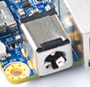
- Power Jack
- DC-12V/2A IN, 5.5*2.1mm Power Jack

- Power Key
- Plug in 12V power at power jack, then press the Power Key ( > 0.5s ) to boot NanoPC-T4.
- USB Port
- USB Type-C port has 2A overcurrent protection.
- USB 3.0 port has 2A overcurrent protection.
- Two USB 2.0 host port share 2A overcurrent protection.
- BOOT Key
- Press BOOT key to prevent the board from eMMC booting, making the board enter MASKROM mode.
- RTC
- RTC backup current is 27uA.
- Connector P/N: Molex 53398-0271
- Notes
- The Power Jack is the only power input port. All power pins at other ports are output.
- How to make T4 start automatically when power is plugged in
- For more details refer to the document: NanoPC-T4-1802-Schematic.pdf
4.2 Board Dimension

- For more details refer to the CAD document: NanoPC-T4_1802_Drawing(dxf).zip
5 Get Started
5.1 Essentials You Need
Before starting to use your NanoPC-T4 get the following items ready
- NanoPC-T4
- Type-C cable
- TF Card: Class 10 or Above, minimum 8GB SDHC
- USB to serial adapter(optinal, for debugging or access from PC host)
- A DC 12V/2A power is a must
- HDMI monitor or LCD
- USB keyboard, mouse and possible a USB hub(or a TTL to serial board)
- A host computer running Ubuntu 18.04 64-bit system
5.2 Debug with Serial Pins
If you want to get T4's boot messages or access T4 remotely you can operate it by using its serial pins.
- Get a USB to serial adapter and connect it to a T4:
Pin# T4's Serial Pins USB to Serial Board 1 GND GND 2 VCC5V0_SYS NC (Not Connected)
Note: if this is a FriendlyElec's Matrix USB2UART you need to turn off the "5V ON/OFF"3 UART2DBG_TX RX 4 UART2DBG_RX TX
- If you connect a USB to Serial adapter to a PC running Linux it will usually be recognized as ttyUSB0. To find out the device name, run the following commands:
 dmesg | grep ttyUSB
 ls -l /dev/ttyUSB*
- On a PC running Linux install and run minicom, and set its configuration as follows(1500000 Bps, 8N1, N)
 sudo apt-get install minicom
 minicom -s
Note: RK3399's debug serial interface's default baud rate is 1500000. Some adapter may not be able to run at this rate. You need to find a working adapter.
5.3 Flash Image to eMMC
As for a RK3399 based ARM board developed by FriendlyELEC there are three ways to flash an image to eMMC:
- Use eflasher to make a bootable SD card and flash an image to eMMC with this card
- Use a Windows' utility "AndroidTool_Release_v2.42" provided by Rockchip to flash an image to eMMC with a Type-C cable
- Use a Linux utility Linux_Upgrade_Tool_1.27 provided by Rockchip to flash an image to eMMC with a Type-C cable
If you are not familiar with the two utilities provided by Rockchip or you don't have a Type-C cable we suggest you try the first method.
5.3.1 Download Image and Utilities
Visit download link to download image files and utilities.
| Image Files | |
| rk3399-eflasher-YYYYMMDD-android.img.zip | Android 7.1.2 image file |
| rk3399-eflasher-YYYYMMDD-friendly-core-arm64.img.zip | 64-bit FriendlyCore image file(Qt 5.10.0) based on Ubuntu core 18.04 |
| rk3399-eflasher-YYYYMMDD-lubuntu.img.zip | Lubuntu Desktop(with Qt 5.10.0) |
| Flash Utility: | |
| win32diskimager.rar | Windows utility. Under Linux users can use "dd" |
5.3.2 Flash Image to eMMC with eflasher and SD card
- Get a 8G SDHC card;
- Download the "rk3399-eflasher-YYYYMMDD-XXXX.img.zip" and "win32diskimager" and extract them on a Windows PC;
- Run the "win32diskimager" utility as administrator, select your TF card, wanted file and click on "Write" to start flash the image to your TF card;
- After it is done take out the TF card and insert it to your T4's microSD slot;
- Connect a 12V/2A DC power cord and an HDMI monitor to your T4, press and hold the Power button for at least 1.5 seconds and you will see the PWR led is on and the image on SD card is booted. Around 15 seconds later the HDMI monitor will display a Window;
- Select your wanted OS with a USB mouse and click on "Next" to continue;
- After flashing is done press and release the Power button to shut down the system. After the PWR is off take out the TF card. Press and hold the Power button for at least 1.5 seconds the image will be booted from eMMC.
5.3.3 Flash Image under Windows with Type-C Cable
Visit download link to download Windows utilities and image files:
| Image Files | |
| android-nougat-images.tgz | Android 7.1.2 Image File |
| core-qte-arm64-images.tgz | FriendlyCore Image File(Qt 5.10) |
| lubuntu-desktop-images.tgz | Lubuntu Desktop with X Window |
| Flash Utility: | |
| AndroidTool_Release_v2.42.7z | Windows utility provided by Rockchip |
| DriverAssitant_v4.5.tgz | USB driver for Windows provided by Rockchip. This is needed when using AndroidTool to flash OS |
Here are the steps:
- Download DriverAssitant_v4.5.tgz, extract it and install it on a Windows PC;
- Download your wanted image from images-for-eflasher and extract it. For example the image for Android 7 is "android-nougat-images.tgz". You can ignore the "idbloader.img" and "info.conf" files.
- Download AndroidTool_Release_v2.42.7z, extract it and run AndroidTool.exe as administrator.
- Import a parameter.txt for sections and configure a file for each section if needed:

- Connect a 12V/2A DC power cord and an HDMI monitor to your T4, connect your T4 to a PC with a Type-C cable. Press and hold the Recovery button and the Power button for at least 1.5 seconds AndroidTools will prompt that a LOADER device is found
a) If eMMC hasn't been flashed with an image or the image inside is removed or damaged this eMMC will be recognized as a MASKROM device;
b) You can hold both the BOOT button and the Power button for at least 5 seconds to force the board to enter the MASKROM mode;
c) If your system shows "no device is found" you need to check if you have installed a driver or if your Type-C cable works and then try it again;
d) If your system is booted successfully you can run "reboot loader" on your board via adb or SSH and force your board to enter the LOADER mode.
- Click on "Run" to download your wanted image to eMMC. A while later after the image is flashed successfully your board will be rebooted automatically.
- If you want to update your system e.g. you want to replace the Linux system on your board with an Android system, you need to erase your eMMC by following the steps below:
Go to "Update Firmware" -> Select "MiniLoaderAll.bin" and then click on "Erase Flasher"

5.3.4 Flash Image to eMMC under Linux with Type-C Cable
Visit download link to download Windows utilities and image files
| Image Files | |
| android-nougat-images.tgz | Android 7.1.2 Image File |
| core-qte-arm64-images.tgz | FriendlyCore Image File(Qt 5.10) |
| lubuntu-desktop-images.tgz | LUbuntu Desktop with X Window |
| Flash Utility: | |
| Linux_Upgrade_Tool_1.27.rar | Linux utility provided by Rockchip |
Linux_Upgrade_Tool is a Linux utility provided by Rockchip. You need to use it together with a Type-C cable. It can be used to install an image to eMMC, delete image files from eMMC, read from and write to eMMC and etc.
- Install upgrade_tool: download Linux_Upgrade_Tool_1.27.rar, extract it and set upgrade_tool's access right
 sudo cp upgrade_tool /usr/local/sbin
 sudo chown root:root /usr/local/sbin/upgrade_tool
 sudo chmod 0755 /usr/local/sbin/upgrade_tool
- Download your wanted image from images-for-eflasher and extract it. For example the image for Lubuntu is "lubuntu-desktop-images.tgz".
- Refer to the steps in "Flash Image to eMMC with AndroidTool" to boot your board and force it to enter either LOADER or MASKROM mode;
- Run the following commands to flash Lubuntu to eMMC and reboot your board:
 sudo upgrade_tool ul MiniLoaderAll.bin
 sudo upgrade_tool di -p parameter.txt
 sudo upgrade_tool di uboot uboot.img
 sudo upgrade_tool di trust trust.img
 sudo upgrade_tool di resource resource.img
 sudo upgrade_tool di kernel kernel.img
 sudo upgrade_tool di boot boot.img
 sudo upgrade_tool di rootfs rootfs.img
 sudo upgrade_tool RD
- If you want to flash Android 7 to eMMC you can download and extract its image file and run the following commands:
 sudo upgrade_tool ul MiniLoaderAll.bin
 sudo upgrade_tool di -p parameter.txt
 sudo upgrade_tool di uboot uboot.img
 sudo upgrade_tool di trust trust.img
 sudo upgrade_tool di misc misc.img
 sudo upgrade_tool di resource resource.img
 sudo upgrade_tool di kernel kernel.img
 sudo upgrade_tool di boot boot.img
 sudo upgrade_tool di recovery recovery.img
 sudo upgrade_tool di system system.img
 sudo upgrade_tool RD
If the image's MiniLoaderAll.bin has a different version or the image you want to flash to eMMC is different from the image that already exists in eMMC you need to erase eMMC and then flash your new image to it.
Boot your board and enter the LOADER mode, run the following commands to erase eMMC. If a prompt shows "Download Boot Start" and it lasts for 10 seconds you need to press the Reset button and run the following commands again.
sudo upgrade_tool EF MiniLoaderAll.binIf it succeeds you will see a prompt showing "Erase flash ok."
5.4 Boot from SD Card
Get the following files from here download link:
- Get a 8G SDHC card and backup its data if necessary.
| Image Files | |
| rk3399-friendlycore-bionic-4.4-arm64-YYYYMMDD.img.zip | FriendlyCore with Qt 5.10.0 (base on Ubuntu core) image file |
| rk3399-lubuntu-desktop-xenial-4.4-armhf-YYYYMMDD.img.zip | LUbuntu Desktop image file with X Window |
| Flash Utility: | |
| win32diskimager.rar | Windows utility. Under Linux users can use "dd" |
- Uncompress these files. Insert an SD card(at least 8G) into a Windows PC and run the win32diskimager utility as administrator. On the utility's main window select your SD card's drive, the wanted image file and click on "write" to start flashing the SD card.
- Insert this card into your board's boot slot and power on, If the PWR LED is on and LED1 is blinking this indicates your board has successfully booted.
6 Work with Android7

FriendlyElec provides a full Android7.1 BSP for NanoPC-T4. The source code is hosted at gitlab.com and is open source. The BSP supports GPU and VPU hardware acceleration.
The NanoPC-T4 supports the FriendlyARM RC-100 remote control under Android. To get a better experience your can connect your T4 to an HDMI monitor and navigate Android.

Here is a table for the remote control's keys and corresponding functions:
Key Function Up Navigate - Up Down Navigate - Down Left Navigate - Left Right Navigate - Right OK Confirm - Volume - + Volume + Mute Mute Menu Android Menu Home Android Home Return Android Return F1 Pull-Down Android Message Bar F2 Android Screenshot F3 Switch between mouse and key
6.2 Connect MIPI Camera to T4
FriendlyElec developed a MIPI camera CAM1320 for NanoPC-T4 and it works under Android. You can use this camera to take pictures and record video. The operation is straightforward. You just need to connect the camera at your NanoPC-T4's MIPI interface, boot your T4 to Android and start Android's camera app.
The NanoPC-T4 has two MIPI interfaces: one front camera and the other rear camera:
Interface Camera Type(front or rear) MIPI-CSI1 Android rear camera MIPI-CSI2 Android front camera
6.3 Set HDMI Display
If your board is connected to an HDMI monitor and it runs Android you can go to "Settings -> Display -> HDMI" to make your setting.
HDMI Resolution By default it is "Auto". You can set its resolution up to 4K Screen Zoom There will be four arrows you can click on to zoom in/out HDMI Rotation Set it landscape or portrait.
6.4 Rotate Display
Enter Android's Settings -> Display -> HDMI -> HDMI Rotation. It supports both landscape and portrait.
7 Work with FriendlyCore
7.1 Introduction
FriendlyCore is a Ubuntu core based OS which doesn't have X Desktop. Its current version is 18.04
FriendlyCore targets enterprise users and is customized for industrial applications. FriendlyCore and Ubuntu base target different users. FriendlyCore has both a commandline utility and a two GUI utilities:
1)Qt 5.10.0 cuustomized for ROCKCHIP3399. It supports GPU and VPU acceleration and has modules like: QtQuick/QtWebEngine/QtMultimedia/WebGL and three display plug-ins:KMS, EGLFS and XCB;
2) Xorg system. It can run X11 applications and supports hardware acceleration;
FriendlyCore for RK3399 has the following features:
- supports FriendlyElec's 7"LCD with capacitive touch - HD702. If a board is connected to both an LCD and an HDMI monitor the LCD and the HDMI monitor can be set to display either differently or the same;
- supports Gstreamer 1.0 multi-media framework;
- supports hard encoding video playing with either commandline utility or Qt player;
- supports Qt5 WebGL;
- supports Qt5 VNC and runs a Qt application as a VNC Server allowing remote control;
- supports bluetooth. It has preinstalled bluez packages;
7.2 System Login
- If your board is connected to an HDMI monitor you need to use a USB mouse and keyboard.
- If you want to do kernel development you need to use a serial communication board, ie a PSU-ONECOM board, which will
You can use a USB to Serial on NanoPC-T4:
- FriendlyCore User Accounts:
Non-root User:
   User Name: pi
   Password: pi
Root:
   User Name: root
   Password: fa
The system is automatically logged in as "pi". You can do "sudo npi-config" to disable auto login.
- Update packages
$ sudo apt-get update
7.3 Configure System with npi-config
The npi-config is a commandline utility which can be used to initialize system configurations such as user password, system language, time zone, Hostname, SSH switch , Auto login and etc. Type the following command to run this utility.
$ sudo npi-config
Here is how npi-config's GUI looks like:

7.4 Develop Qt Application
The Qt 5.10.0 FriendlyELEC ported for RK3399 supports the following plug-ins:KMS, EGLFS and XCB. All these three plug-ins support OpenGL ES and GPU hardware acceleration but in different ways:
- KMS - it calls Linux kernel's DRM interface to display
- EGLFS - it calls OpenGL ES interface to display
- XCB - it runs on X11 server and is integrated in X11 windows system
Three plug-ins support different Qt features and here is a table:
Plug-in OpenGL ES QtWebEngine QtMultimedia Video Playing with Hardware Decoding Different Display KMS Yes No Yes No Yes EGLFS Yes No Yes No No XCB Yes Yes Yes Yes Yes
We recommend to use KMS or XCB.
FriendlyCore has four scripts for setting Qt environmental variables for users and here is a table:
Script Comment /usr/bin/setqt5env-kms set kms' environmental variables /usr/bin/setqt5env-eglfs set eglfs' environmental variables /usr/bin/setqt5env-xcb set xcb's environmental variables /usr/bin/setqt5env-nogui set environmental variables for a system without a Qt GUI
For instance, if you want to use KMS to display you can run the following commands:
. setqt5env-kms
./apps
(Note:there is a space between '.' and 's')
7.4.1 Setup Qt Development Envronment
FriendlyELEC developed two methods for RK3399 to cross-compile a Qt program:
- 1:Use Docker. For more details you can refer to github :http://github.com/friendlyarm/friendlyelec-ubuntu18-docker
- 2:Setup a local cross-compiler. You need to run a Ubuntu 18.04 64-bit OS and you can refer to :How to Build and Install Qt Application for FriendlyELEC Boards/zh
7.4.2 Qt Demo
FriendlyCore has several Qt demo programs:
- Qt QML: CinematicExperience
CinematicExperience is a utility for selecting a video file and it is developed with Qt QML.
This demo uses Qt QML's various features and runs very smoothly on RK3399. This performance is achieved by hardware and software optimization.
You can start it in a commandline utility by running the following commands:
cd /opt/Qt5_CinematicExperience
./run.sh
Here is what it looks like:

- QQt WebEngine: web browser
Qt WebEngine uses Chromium and supports HTML5.
You can start it by running the following commands:
cd /opt/qt5-brower
./run.sh
Here is what it looks like:

Note:Qt WebEngine depends on the Xcb plug-in.
- Qt Different Display
This demo shows that when a board is connected to an HDMI monitor and an eDP LCD these two devices display differently. You can start it by running the following commands:
cd /opt/qt5-multi-screen-demo
./run.sh
Here is what it looks like:

- Qt Multimedia: qt5-player with hard decoding
The qt5-player works with Rockchip's gstreamer plug-in and supports 4K video playing. Since Rockchip's plug-in only supports output images to an X11 window the qt5-player needs to use XCB for display.
You can start the demo by running the following commands:
cd /opt/qt5-player
./run.sh
Here is what it looks like. You can set it to display in full-screen and adjust the voice's volume:

- Qt WebGL demo: nmapper
Qt WebGL allows you to remotely access a Qt program running on your board.
Before you run the demo you need to connect your board to the internet and run the following commands:
cd /opt/qt5-nmapper
./run-with-webgl.sh
You can open a browser on another device, type the IP address of your board on the browser's address bar, enter and you will be able to see a Qt GUI. Here is what it looks like:

- Qt VNC demo: Smart home applicance GUI
Qt VNC allows you to run a program as a VNC Server on your board and you can access the program from a VNC client on another device. This program can be developed with either QtWidgets or QML.
You can start it by running the following commands:
cd /opt/qt5-smarthome
./run-with-vnc.sh
Start a VNC viewer on a smart phone or mobile device and type your board's IP address and port number 5900. For instance if your board's IP address is 192.168.1.100 you can type "192.168.1.100:5900", enter and you will see the following GUI:

7.4.3 Play with Dual Cameras under Qt
This sample shows how to connect dual cameras to the board and play with them. Before run the sample make sure you connect dual cameras and an LCD to your board. In general popular UVC cameras should work however we suggest users use the following modules which we have tested:
Index Model 1 Logitech C270 2 Logitech C270i 3 Logitech C922 Pro
Run the following commands:
cd /opt/dual-camera
./run.sh
Here is what you expect to observe:

7.5 Setup Program to AutoRun
You can setup a program to autorun on system boot with npi-config:
sudo npi-configGo to Boot Options -> Autologin -> Qt/Embedded, select Enable and reboot.
7.6 Extend TF Card's Section
When FriendlyCore is loaded the TF card's section will be automatically extended.You can check the section's size by running the following command:
$ df -h
7.7 Transfer files using Bluetooth
Take the example of transferring files to the mobile phone. First, set your mobile phone Bluetooth to detectable status, then execute the following command to start Bluetooth search.:
hcitool scan
Search results look like:
Scanning ...
    2C:8A:72:1D:46:02   HTC6525LVW
This means that a mobile phone named HTC6525LVW is searched. We write down the MAC address in front of the phone name, and then use the sdptool command to view the Bluetooth service supported by the phone:
sdptool browser 2C:8A:72:1D:46:02
Note: Please replace the MAC address in the above command with the actual Bluetooth MAC address of the mobile phone.
This command will detail the protocols supported by Bluetooth for mobile phones. What we need to care about is a file transfer service called OBEX Object Push. Take the HTC6525LVW mobile phone as an example. The results are as follows:
Service Name: OBEX Object Push
Service RecHandle: 0x1000b
Service Class ID List:
  "OBEX Object Push" (0x1105)
Protocol Descriptor List:
  "L2CAP" (0x0100)
  "RFCOMM" (0x0003)
    Channel: 12
  "OBEX" (0x0008)
Profile Descriptor List:
  "OBEX Object Push" (0x1105)
    Version: 0x0100
As can be seen from the above information, the channel used by the OBEX Object Push service of this mobile phone is 12, we need to pass it to the obexftp command, and finally the command to initiate the file transfer request is as follows:
obexftp --nopath --noconn --uuid none --bluetooth -b 2C:8A:72:1D:46:02 -B 12 -put example.jpg
Note: Please replace the MAC address, channel and file name in the above command with the actual one.
After executing the above commands, please pay attention to the screen of the mobile phone. The mobile phone will pop up a prompt for pairing and receiving files. After confirming, the file transfer will start.
Bluetooth FAQ:
1) Bluetooth device not found on the development board, try to open Bluetooth with the following command:
rfkill unblock 02) Prompt can not find the relevant command, you can try to install related software with the following command:
apt-get install bluetooth bluez obexftp openobex-apps python-gobject ussp-push7.8 WiFi
For either an SD WiFi or a USB WiFi you can connect it to your board in the same way. The APXX series WiFi chips are SD WiFi chips. By default FriendlyElec's system supports most popular USB WiFi modules. Here is a list of the USB WiFi modules we tested:
Index Model 1 RTL8188CUS/8188EU 802.11n WLAN Adapter 2 RT2070 Wireless Adapter 3 RT2870/RT3070 Wireless Adapter 4 RTL8192CU Wireless Adapter 5 mi WiFi mt7601 6 5G USB WiFi RTL8821CU 7 5G USB WiFi RTL8812AU
You can use the NetworkManager utility to manage network. You can run "nmcli" in the commandline utility to start it. Here are the commands to start a WiFi connection:
- Change to root
$ su root
- Check device list
$ nmcli devNote: if the status of a device is "unmanaged" it means that device cannot be accessed by NetworkManager. To make it accessed you need to clear the settings under "/etc/network/interfaces" and reboot your system.
- Start WiFi
$ nmcli r wifi on- Scan Surrounding WiFi Sources
$ nmcli dev wifi- Connect to a WiFi Source
$ nmcli dev wifi connect "SSID" password "PASSWORD" ifname wlan0
The "SSID" and "PASSWORD" need to be replaced with your actual SSID and password.If you have multiple WiFi devices you need to specify the one you want to connect to a WiFi source with iface
If a connection succeeds it will be automatically setup on next system reboot.
For more details about NetworkManager refer to this link: Use NetworkManager to configure network settings
If your USB WiFi module doesn't work most likely your system doesn't have its driver. For a Debian system you can get a driver from Debian-WiFi and install it on your system. For a Ubuntu system you can install a driver by running the following commands:
$ apt-get install linux-firmware
In general all WiFi drivers are located at the "/lib/firmware" directory.
7.9 Ethernet Connection
If a board is connected to a network via Ethernet before it is powered on it will automatically obtain an IP with DHCP activated after it is powered up. If you want to set up a static IP refer to: Use NetworkManager to configure network settings。
7.10 WiringPi and Python Wrapper
7.11 Custom welcome message
The welcome message is printed from the script in this directory:
/etc/update-motd.d/
For example, to change the FriendlyELEC LOGO, you can change the file /etc/update-motd.d/10-header. For example, to change the LOGO to HELLO, you can change the following line:
TERM=linux toilet -f standard -F metal $BOARD_VENDOR
To:
TERM=linux toilet -f standard -F metal HELLO
7.12 Modify timezone
For exampe, change to Shanghai timezone:
sudo rm /etc/localtime
sudo ln -ls /usr/share/zoneinfo/Asia/Shanghai /etc/localtime
7.13 Select the system default audio device
You can set the system default audio device by following the steps below.
Use the following command to view all the sound card devices in the system (Note: different development boards will have different results):
pi@NanoPi:~$ aplay -l
**** List of PLAYBACK Hardware Devices ****
card 0: realtekrt5651co [realtek,rt5651-codec], device 0: ff880000.i2s-rt5651-aif1 rt5651-aif1-0 []
  Subdevices: 1/1
  Subdevice #0: subdevice #0
card 1: rockchiphdmi [rockchip,hdmi], device 0: ff8a0000.i2s-i2s-hifi i2s-hifi-0 []
  Subdevices: 1/1
  Subdevice #0: subdevice #0
card 2: ROCKCHIPSPDIF [ROCKCHIP,SPDIF], device 0: ff870000.spdif-dit-hifi dit-hifi-0 []
  Subdevices: 1/1
  Subdevice #0: subdevice #0
As you can see, the following sound card devices are available on the hardware:
Sound card device Sound card number Description realtekrt5651co 0 Realtek sound card's default output interface (through 3.5mm jack interface) rockchiphdmi 1 HDMI ROCKCHIPSPDIF 2 SPDIF (Note: temporarily unavailable, because the hardware is not exported)...
To configure the audio output to the 3.5mm jack, modify the configuration file /etc/asound.conf and modify it to the following:
defaults.pcm.card 0
defaults.pcm.device 0
To configure to output audio to HDMI, change the defaults.pcm.card above to 1.
Note that some boards do not have a Realtek sound card (no 3.5mm jack interface), so the card number of the HDMI device will be 0, so the configuration should be based on the result of the aplay -l command.
7.14 Change the behavior of the PWM fan
By default, the speed of the fan is dynamically adjusted according to the CPU temperature. If you need to let the fan run, you can modify the script /usr/bin/start-rk3399-pwm-fan.sh to the following:
#!/bin/bash

echo 0 > /sys/class/pwm/pwmchip1/export
sleep 1
echo 0 > /sys/class/pwm/pwmchip1/pwm0/enable
echo 50000 > /sys/class/pwm/pwmchip1/pwm0/period
echo 1 > /sys/class/pwm/pwmchip1/pwm0/enable
echo 45000 > /sys/class/pwm/pwmchip1/pwm0/duty_cycle
8 Work with Lubuntu
8.1 Introduction to Lubuntu


LUbuntu is a light-weighted Ubuntu desktop system. It is based on LXDE and has the following features:
Light-weighted - it consumes relatively less CPU resources than a common desktop system. When a system's RAM is sufficient it can achieve much better performance.
Less power consumption - it consumes relatively less power or resources than a common desktop system to achieve the same performance.
Compact & neat - its desktop is based on GTK+ 2 and supports multiple languages.
Easy to use - its GUI looks similar to MS Windows'.
Customizable - Users can customize LXDE's GUI.
Compatible - it is compatible with freedesktop.org.
The Lubuntu Desktop has been optimized for adopting Mali GPU. It has driver support for X.org and supports Hardware Cursor, OpenGL acceleration and etc.
8.2 Lubuntu Default User Account
Non-root User:
   User Name: pi
   Password: pi
Root:
   User Name: root
   Password: fa
8.3 OpenGL ES
Open a command line utility and run the following command:
glmark2-es2

8.4 Video Playing with Hardware Decoding
8.4.1 Video Playing with Qt Player
Lubuntu is preinstalled with Qt5-Player which has Rockchip's gstreamer plug-in and supports playing 4K video stream. Here are the steps to start it:
On Lubuntu's main window open "Other" and click on Qt5-Player
Here is how this player looks like. It can display in full screen. You can adjust its volume:

8.4.2 Video Playing with Commandline Utility
Open a commandline utility and type the following command:
gst-player.sh
Your selected video file will be played in Overlay and its voice will be output to the earphone. You can use "which gst-player.sh" to locate this script and customize it.
8.5 eDP LCD Rotation
If your board is connected to an eDP LCD and you want to rotate its display by 90/180/270 degrees you can do it with "xrotate.sh". You can run the following command as root to rotate its display by 90 degrees clockwise. It will start the lightdm service to make it effective:
sudo xrotate.sh -m UD -r
You can get more details by running "xrotate -h".
However this command cannot rotate HDMI display. If you want to rotate HDMI display you may need to make changes in "/etc/X11/xorg.conf"
8.6 Connect USB Camera to T4
Connect a USB camera (e.g. Logitech C270) to T4, start Lubuntu, enter the "Other" menu, start "xawtv" and you will be able to preview with the camera.
8.7 5G WiFi
Click on the network icon on top right of the Lubuntu GUI, select a WiFi hotspot and proceed with prompts.
8.8 Develop Qt Application
Lubuntu has Qt 5.10.0 which can be used to develop an X11 application. For details about SDK download and compilation refer to :How to Build and Install Qt Application for FriendlyELEC Boards
8.9 Connect NVME SSD High Speed Hard Disk to T4
Connect a NVME SSD hard disk to NanoPC-T4's M.2 interface, initialize and automatically mount the SSD by running the following commands. Before proceed turn off your T4 and connect an SSD to your T4. Power on your T4 and open a command line utility(go to top left of the GUI and enter System Tools -> LXTerminal) or SSH to your T4.
We suggest you switch to "root" by running the following command:
su -The password for "root" is "fa".
8.9.1 Detection of SSD
root@FriendlyELEC:~# cat /proc/partitions
major minor  #blocks  name
   1        0       4096 ram0
 259        0  125034840 nvme0n1
If there is a nvme0n1 device node it means an SSD is recognized by T4.
8.9.2 Partition of SSD
To mount an SSD under Linux we re-partition it as one section by running the following command:
(echo o; echo n; echo p; echo 1; echo ""; echo ""; echo w; echo q) | fdisk /dev/nvme0n1
If you want to re-partition it to multiple sections you can run "fdisk /dev/nvme0n1". For more detail about this command refer to the fdisk's manual.
8.9.3 Format Section to EXT4
After an SSD is successfully partitioned you can check its sections by running "cat /proc/partitions". The image provided treats a PCIe nvme device's sections as an eMMC's sections you will find that an SSD has some small sections.
We can check the "blocks" column and the biggest section is available for users. The /dev/nvme0n1p7 section is used to store data:
root@FriendlyELEC:~# cat /proc/partitions
major minor  #blocks  name
   1        0       4096 ram0
 259        0  125034840 nvme0n1
 259        1       4096 nvme0n1p1
 259        2       4096 nvme0n1p2
 259        3       4096 nvme0n1p3
 259        4      12288 nvme0n1p4
 259        5      32768 nvme0n1p5
 259        6      32768 nvme0n1p6
 259        7  124932440 nvme0n1p7
The following command formats a section to ext4:
mkfs.ext4 /dev/nvme0n1p7
8.9.4 Auto Mount SSD on System Startup
Before we mount an SSD's section you need to know its Block ID. You can check it by running "blkid":
blkid /dev/nvme0n1p7
/dev/nvme0n1p7: UUID="13fb682e-ef40-4c71-b98b-3d17403e1205" TYPE=“ext4"
Add a "Block ID" to "/etc/fstab" and here is what it looks like
UUID=<Block ID> /media/nvme ext4 defaults 0 0
You need to replace <Block ID> with the UUID obtained by running "blkid". To mount the SSD in our example we made the "/etc/fstab" file as follows:
UUID=13fb682e-ef40-4c71-b98b-3d17403e1205 /media/nvme ext4 defaults 0 0
We want to mount an SSD to "/media/nvme" but this directory doesn't exist. Therefore we create it and change its access right by running the following commands:
mkdir /media/nvme
chmod 777 /media/nvme
Run "mount" to check if the SSD is mounted successfully:
mount /media/nvme
You can reboot your T4 to check if your SSD will be automatically mounted:
poweroff
Reboot your T4, if you can see the following screen your SSD is mounted successfully:

8.9.5 SSD Read & Write
You can test SSD read and write speed. In our test we used a LITEON T10 120GB SSD. Different SSDs may have different results.
Write to SSD:
# dd if=/dev/zero of=/media/nvme/deleteme.dat bs=32M count=128
128+0 records in
128+0 records out
4294967296 bytes (4.3 GB, 4.0 GiB) copied, 12.5671 s, 342 MB/s
Read from SSD:
# dd if=/media/nvme/deleteme.dat of=/dev/zero bs=32M count=128
128+0 records in
128+0 records out
4294967296 bytes (4.3 GB, 4.0 GiB) copied, 6.72943 s, 638 MB/s
9 Make Your Own OS Image
9.1 Setup Development Environment
If you want to compile an Android image we suggest you use a PC running a 64-bit Ubuntu 16.04.
sudo apt-get install bison g++-multilib git gperf libxml2-utils make python-networkx zip
sudo apt-get install flex curl libncurses5-dev libssl-dev zlib1g-dev gawk minicom
sudo apt-get install openjdk-8-jdk
sudo apt-get install exfat-fuse exfat-utils device-tree-compiler liblz4-tool
For more details refer to https://source.android.com/source/initializing.html 。
9.2 Install Cross Compiler
9.2.1 Install aarch64-linux-gcc 6.4
Download and extract compiler:
git clone https://github.com/friendlyarm/prebuilts.git
sudo mkdir -p /opt/FriendlyARM/toolchain
sudo tar xf prebuilts/gcc-x64/aarch64-cortexa53-linux-gnu-6.4.tar.xz -C /opt/FriendlyARM/toolchain/
Add the compiler's path to the PATH variable by appending the following lines to the "~/.bashrc" file:
export PATH=/opt/FriendlyARM/toolchain/6.4-aarch64/bin:$PATH
export GCC_COLORS=auto
Run the "~/.bashrc" script to make the compiler setting effective in the current shell. Note:there is a space after ".":
. ~/.bashrcThis is a 64-bit compiler and cannot be run on a 32-bit Linux. After installation is done you can verify it by running the following commands:
aarch64-linux-gcc -v
Using built-in specs.
COLLECT_GCC=aarch64-linux-gcc
COLLECT_LTO_WRAPPER=/opt/FriendlyARM/toolchain/6.4-aarch64/libexec/gcc/aarch64-cortexa53-linux-gnu/6.4.0/lto-wrapper
Target: aarch64-cortexa53-linux-gnu
Configured with: /work/toolchain/build/aarch64-cortexa53-linux-gnu/build/src/gcc/configure --build=x86_64-build_pc-linux-gnu
--host=x86_64-build_pc-linux-gnu --target=aarch64-cortexa53-linux-gnu --prefix=/opt/FriendlyARM/toolchain/6.4-aarch64
--with-sysroot=/opt/FriendlyARM/toolchain/6.4-aarch64/aarch64-cortexa53-linux-gnu/sysroot --enable-languages=c,c++
--enable-fix-cortex-a53-835769 --enable-fix-cortex-a53-843419 --with-cpu=cortex-a53
...
Thread model: posix
gcc version 6.4.0 (ctng-1.23.0-150g-FA)
9.3 Compile Android7 Source Code
9.3.1 Download Android7 Source Code
All the NanoPC-T4's source code is hosted at gitlab, you can download it by running the following commands:
git clone https://gitlab.com/friendlyelec/rk3399-nougat.git
9.3.2 Compile & Make Image File
Compile Android7 by running the following commands:
cd rk3399-nougat
./build-nanopc-t4.sh -F -M
9.3.3 Update Image File
After compilation is done an image file will be generated under Android7's "rockdev/Image-nanopc_t4/" directory. Update the image file on T4 by running the following commands:
1) Insert a bootable SD card with EFLASHER to a card adapter and insert this adapter to a host PC and the SD card's sections will be automatically mounted;
2) Copy all the files under "rockdev/Image-nanopc_t4/" to the "nougat" directory of this SD card's FRIENDLYARM section;
3) Insert this SD card to your NanoPC-T4 and reinstall Android;
9.4 Compile Lubuntu Kernel
9.4.1 compile Linux kernel
git clone https://github.com/friendlyarm/kernel-rockchip --depth 1 -b nanopi4-linux-v4.4.y
cd kernel-rockchip
make ARCH=arm64 nanopi4_linux_defconfig
make ARCH=arm64 nanopi4-images
9.4.2 Update Lubuntu Kernel
To update the kernel you need to use the Linux_Upgrade_Tool_1.27.rar utility. Refer to the aforementioned sections on how to use this utility.
9.5 Access Serial Interface
For now only UART4 is available for users:
Serial Interface Serial Device UART0 Used by Bluetooth UART1 Used by Gbps Ethernet UART2 Used by Serial Debug Port UART3 Used by Gbps Ethernet UART4 Available, device name is /dev/ttyS4 (note: this is only applicable for ROM released after 20180618)
10 More OS Support
10.1 DietPi_NanoPCT4-ARMv8-Stretch
DietPi is a light-weighted system. Its image file can be as small as 345M bytes. It takes much less resources. It has a DietPi-RAMlog utility. These features allow users to exploit its huge potentials.
FriendlyElec doesn't provide technical support for DietPi.
Here are some steps to boot a DietPi:
- Download DriverAssitant_v4.5.tgz, extract it and install it on a Windows PC;
- Download DietPi_NanoPCT4-ARMv8-Stretch DietPi_NanoPCT4-ARMv8-Stretch, extract it, enter "Image_and_Tools" and run "AndroidTool.exe" as administrator
- It is assumed that the section configuration(parameter.txt) is imported and here is a table:

- Connect a 12V/2A DC power cord and an HDMI monitor to your T4, connect your T4 to a PC with a Type-C cable. Press and hold the Recovery button and the Power button for at least 1.5 seconds AndroidTools will prompt that a LOADER device is found
a)If eMMC hasn't been flashed with an image or the image inside is removed or damaged this eMMC will be recognized as a MASKROM device;
b)You can hold both the BOOT button and the Power button for at least 5 seconds to force the board to enter the MASKROM mode;
c)If your system shows "no device is found" you need to check if you have installed a driver or if your Type-C cable works and then try it again;
d)If your system is booted successfully you can run "reboot loader" on your board via adb or SSH and force your board to enter the LOADER mode.
- Click on "Run" to download your wanted image to eMMC. A while later after the image is flashed successfully your board will be rebooted automatically.

Login User Name:root
Password:dietpi
10.2 WiFi
By default WiFi is not enabled. You can enable WiFi by running "dietpi-config". dietpi-config
   --> Network Options:Adapters
       --> WiFi  Change Wireless Network Settings
           --> Scan  Scan and Connect
Select a WiFi hotspot, type its password and connect

11 Link to Rockchip Resources
- Link to Rockchip's resources: https://gitlab.com/friendlyelec/rk3399-nougat/tree/nanopc-t4-nougat/RKDocs
- RK3399 datasheet V1.6
- RK3399TRM V1.4
12 Schematic, PCB CAD File
- Schematic: NanoPC-T4-1802-Schematic.pdf
- PCB CAD File:NanoPC-T4_1802_Drawing(dxf).zip
13 Update Log
13.1 June-19-2018
- Released English version
13.2 July-5-2018
- Updated section 5.3
- Added sections 7, 9.2 and 10
13.3 July-27-2018
- Updated section 5.3
- Added sections 9.5 and 9.8
13.4 July-29-2018
- Updated section 6.2
- Added sections 7.4, 8.4 and 9.4