Difference between revisions of "BakeBit - NanoHat Hub"
(→Hardware Spec) |
(→Hardware Spec) |
||
| Line 65: | Line 65: | ||
* '''I2C Interface''' | * '''I2C Interface''' | ||
| − | There three 5V I2C interfaces on the top row. The first pin | + | There three 5V I2C interfaces on the top row. The first pin from the left is SCL and the second pin is SDA. |
{| class="wikitable" | {| class="wikitable" | ||
|- | |- | ||
| Line 79: | Line 79: | ||
|} | |} | ||
* '''Analog Interface''' | * '''Analog Interface''' | ||
| − | There are three analog interfaces on the second row. The first pin | + | There are three analog interfaces on the second row. The first pin from the left is An and the second pin is An+1. For example A0/A1 stands for the first pin A0 and the second pin A1 from the left. Usually it is abbreviated as A0. |
{| class="wikitable" | {| class="wikitable" | ||
|- | |- | ||
| Line 93: | Line 93: | ||
|} | |} | ||
* '''UART Interface''' | * '''UART Interface''' | ||
| − | The NEO-Hub has two UART interfaces. When you connect the NEO-Hub to the NanoPi NEO/AIR the first UART on the third row is directly connected to the NEO/AIR's UART1. The second UART is the UART populated from NEO-Hub's chipset and this UART can be used as D0/D1. | + | The NEO-Hub has two UART interfaces. When you connect the NEO-Hub to the NanoPi NEO/AIR the first UART on the third row from the left is directly connected to the NEO/AIR's UART1. The second UART is the UART populated from NEO-Hub's chipset and this UART can be used as D0/D1. |
{| class="wikitable" | {| class="wikitable" | ||
|- | |- | ||
| Line 106: | Line 106: | ||
|4 || GND || Ground | |4 || GND || Ground | ||
|} | |} | ||
| − | * ''' | + | * '''Digital Interface''' |
| − | + | The remaining four are digital interfaces. The fist from the left is Dn and the second is Dn+1. For example D2/D3 stands for the first pin D2 and the second pin D3 from the left. Usually it is abbreviated as D2. | |
| − | + | Among these 5 digital interfaces D2-D6 D3, D5 and D6 can be used as PWM. | |
{| class="wikitable" | {| class="wikitable" | ||
|- | |- | ||
| − | | | + | |Pin ||Name || Description |
|- | |- | ||
| − | |1 || Dn || | + | |1 || Dn || Digital Interface Dn |
|- | |- | ||
| − | |2 || Dn+1 || | + | |2 || Dn+1 || Digital Interface Dn+1 |
|- | |- | ||
| − | |3 || 5V || | + | |3 || 5V || 5V supply voltage |
|- | |- | ||
| − | |4 || GND || | + | |4 || GND || Ground |
|} | |} | ||
Revision as of 09:12, 9 December 2016
1 Introduction
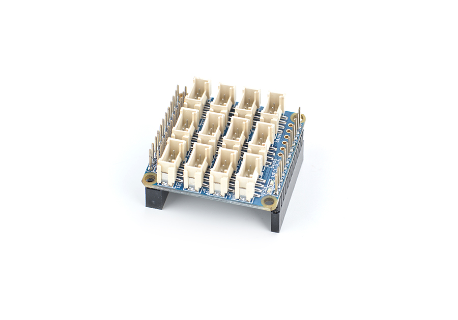
- The NEO-Hub is a plug & play extension board.The NEO-Hub communicate with the NanoPi NEO/AIR via its I2C interface. It acts as an interface between the NanoPi NEO/AIR and various external modules. The NEO-Hub has 3 I2C interfaces,3 analog interfaces,2 UART interfaces and 4 digital interfaces (among which D3 and D5 support PWM).All the BakeBit modules can be connected to the NEO-Hub with a 4-pin cable.
- The NEO-Hub can be mounted on the NanoPi NEO/AIR with male connectors.The NEO-Hub communicates with various external modules via its I2C, serial and A/D interfaces.
- The NEO-Hub has 3 I2C interfaces,3 analog interfaces,2 UART interfaces and 4 digital interfaces (among which D3 and D5 support PWM).
2 Hardware Spec
- Compatible with NanoPi NEO/AIR
- 3 x 2.0mm pitch 4Pin I2C Interface
- 3 x 2.0mm pitch 4Pin Analog Interface
- 1 x 2.0mm pitch URAT-NEO Interface
- 1 x 2.0mm pitch URAT-Hub Interface
- 4 x 2.0mm pitch Digital Interface
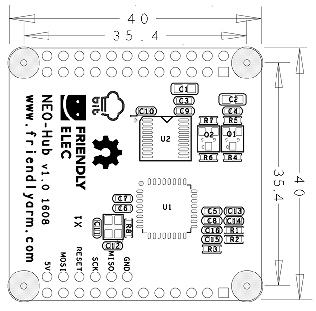
- PCB dimension (mm): 40 x 40
- Pin Spec:
- 24 Pin Spec
| Pin# | Name | Pin# | Name |
| 1 | SYS_3.3V | 2 | VDD_5V |
| 3 | I2C0_SDA | 4 | VDD_5V |
| 5 | I2C0_SCL | 6 | GND |
| 7 | GPIOG11 | 8 | UART1_TX/GPIOG6 |
| 9 | GND | 10 | UART1_RX/GPIOG7 |
| 11 | UART2_TX/GPIOA0 | 12 | PWM1/GPIOA6 |
| 13 | UART2_RTS/GPIOA2 | 14 | GND |
| 15 | UART2_CTS/GPIOA3 | 16 | UART1_RTS/GPIOG8 |
| 17 | SYS_3.3V | 18 | UART1_CTS/GPIOG9 |
| 19 | SPI0_MOSI/GPIOC0 | 20 | GND |
| 21 | SPI0_MISO/GPIOC1 | 22 | UART2_RX/GPIOA1 |
| 23 | SPI0_CLK/GPIOC2 | 24 | SPI0_CS/GPIOC3 |
- 12 Pin Spec
| Pin# | Name | Description |
| 1 | VDD_5V | 5V Power In/Out |
| 2---11 | NC | Not Connected |
| 12 | GND | 0V |
- Each BakeBit interface is a 2.0mm pitch 4pin connector. Here is its specification:
- I2C Interface
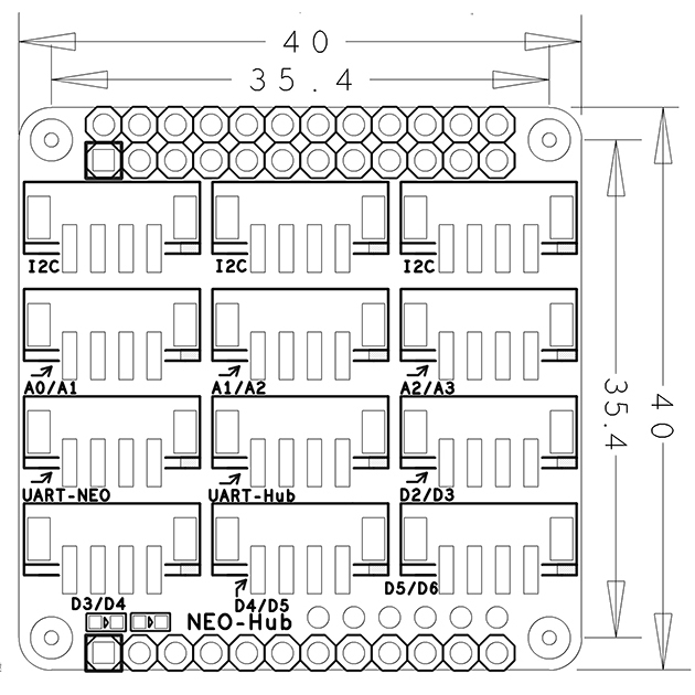
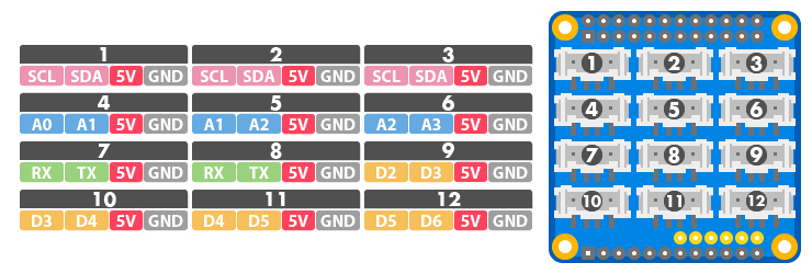
There three 5V I2C interfaces on the top row. The first pin from the left is SCL and the second pin is SDA.
| Pin | Name | Description |
| 1 | SCL | SCL |
| 2 | SDA | SDA |
| 3 | 5V | 5V supply voltage |
| 4 | GND | Ground |
- Analog Interface
There are three analog interfaces on the second row. The first pin from the left is An and the second pin is An+1. For example A0/A1 stands for the first pin A0 and the second pin A1 from the left. Usually it is abbreviated as A0.
| Pin | Name | Description |
| 1 | An | Analog An |
| 2 | An+1 | Analog An+1 |
| 3 | 5V | 5V supply voltage |
| 4 | GND | Ground |
- UART Interface
The NEO-Hub has two UART interfaces. When you connect the NEO-Hub to the NanoPi NEO/AIR the first UART on the third row from the left is directly connected to the NEO/AIR's UART1. The second UART is the UART populated from NEO-Hub's chipset and this UART can be used as D0/D1.
| Pin | Name | Description |
| 1 | Rx | Receiver |
| 2 | Tx | Transmitter |
| 3 | 5V | 5V supply voltage |
| 4 | GND | Ground |
- Digital Interface
The remaining four are digital interfaces. The fist from the left is Dn and the second is Dn+1. For example D2/D3 stands for the first pin D2 and the second pin D3 from the left. Usually it is abbreviated as D2.
Among these 5 digital interfaces D2-D6 D3, D5 and D6 can be used as PWM.
| Pin | Name | Description |
| 1 | Dn | Digital Interface Dn |
| 2 | Dn+1 | Digital Interface Dn+1 |
| 3 | 5V | 5V supply voltage |
| 4 | GND | Ground |
3 使用方法
BakeBit - NEO Hub连接NanoPi NEO的使用方法参考以下链接:BakeBit - NEO Hub连接NanoPi NEO的使用方法
4 支持的模块
可以和BakeBit - NEO Hub连接使用的模块如下:
- 1、按键模块
- 2、蜂鸣器模块
- 3、绿色LED模块
- 4、摇杆模块
- 5、LED Bar模块
- 6、光敏模块
- 7、OLED模块
- 8、红色LED模块
- 9、旋转角度模块
- 10、舵机模块
- 11、声音模块
- 12、超声波模块
5 升级NEO Hub固件
升级BakeBit固件的实质是,将新版本的固件文件(名为bakebit_firmware.hex)烧写到NEO-Hub的芯片内,下面的内容是具体的步骤:
先在NanoPi NEO上安装 avrdude:
apt-get install avrdude再用vi编辑配置文件 /etc/avrdude.conf,在文件最末尾加入如下内容:
# Linux GPIO configuration for avrdude.
# Change the lines below to the GPIO pins connected to the AVR.
programmer
  id    = "nanopineo";
  desc  = "Use the Linux sysfs interface to bitbang GPIO lines";
  type  = "linuxgpio";
  reset = 67;
  sck   = 66;
  mosi  = 64;
  miso  = 65;
;
然后进入Firmware目录,执行firmware_update.sh脚本上传固件:
cd ~/BakeBit/Firmware
./firmware_update.sh
根据脚本的提示选择y, 固件更新成功的提示如下所示:
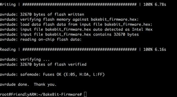
正如你所见,固件是一个名为.hex的二进制文件,你可以使用脚本 new_fw_search.sh 在线检查一下官方是否有新版本。
6 使用Arduino IDE编译固件
1) 先在电脑上安装Arduino IDE,Arduino IDE到这里下载:
https://www.arduino.cc/en/Main/Software
2) 把BakeBit/Firmware/Source/下的FastLED-FastLED3.1目录复制到Arduino IDE安装目录下的libraries子目录,在macOS下该路径为: /Applications/Arduino.app/Contents/Java/libraries/
3) 用Arduino IDE打开BakeBit项目文件:
BakeBit/Firmware/Source/bakebit_v1.0.0/bakebit_v1.0.0.ino
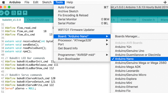
4) 在Arduino上进入Tools菜单,把Board的类型改为Arduino Nano:
5) 在Arduino上进入Sketch菜单,选择 Export Compliled Binary,Arduino将执行编译。
6) 编译成功后,在源代码目录下, 会生成一个名为bakebit_v1.0.0.ino.eightanaloginputs.hex的二进制文件,将其更名为 bakebit_firmware.hex,上传到NanoPi NEO上并覆盖BakeBit/Firmware/下的同名文件,用上一章节介绍的方法,执行firmware_update.sh脚本重新烧写固件即可。
7 相关资料
- [Schematic](BakeBit - NEO Hub.pdf)
