NanoPi NEO Plus2/zh
Contents
- 1 介绍
- 2 资源特性
- 3 接口布局和尺寸
- 4 快速入门
- 5 Work with FriendlyCore
- 5.1 Introduction
- 5.2 System Login
- 5.3 Configure System with npi-config
- 5.4 Develop Qt Application
- 5.5 Setup Program to AutoRun
- 5.6 Extend TF Card's Section
- 5.7 Transfer files using Bluetooth
- 5.8 WiFi
- 5.9 Ethernet Connection
- 5.10 Custom welcome message
- 5.11 Modify timezone
- 5.12 Set Audio Device
- 5.13 Connect to USB Camera(FA-CAM202)
- 5.14 Check CPU's Working Temperature
- 5.15 Test Watchdog
- 5.16 Test Infrared Receiver
- 5.17 Read CHIP ID
- 5.18 Access GPIO Pins/Wirings with WiringNP
- 5.19 Run Qt Demo
- 5.20 How to install and use docker (for arm64 system)
- 5.21 播放和录制音频
- 6 如何编译FriendlyCore系统
- 7 使用扩展配件及编程示例
- 8 3D 打印外壳
- 9 资源链接
1 介绍
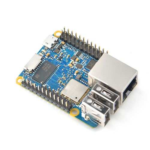
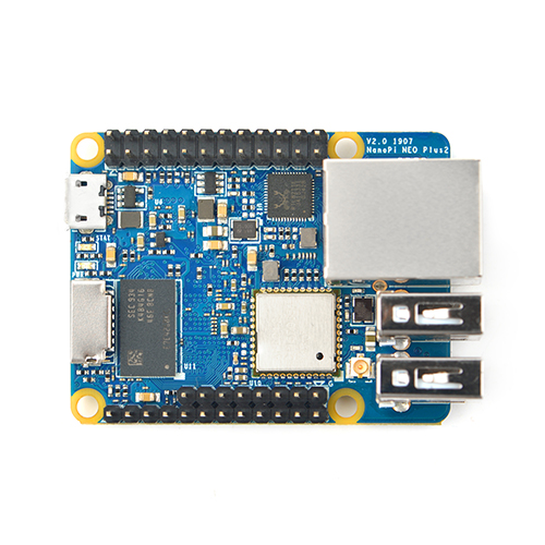
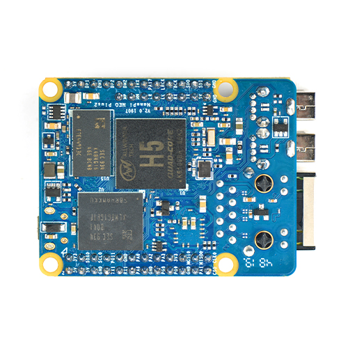
- NanoPi NEO Plus2是友善电子团队推出的又一款小巧ARM计算机,它采用全志64位四核A53处理器H5,内置六核Mali450 GPU,集成1GB DDR3内存,标配 8GB eMMC高速闪存。
- NanoPi NEO Plus2依然小巧精致,尽管尺寸仅有40x52mm,却板载了AP6212A WiFi蓝牙模块,以及千兆以太网接口,板子引出了双路标准USB接口,支持从MicroSD卡启动运行系统。
- NanoPi NEO Plus2采用了专业的电源系统设计,采用6层板布线,具有良好的散热特性。适合对体积要求高,数据传输量大,数据传输速度快,和更高计算性能的物联网应用。
2 资源特性
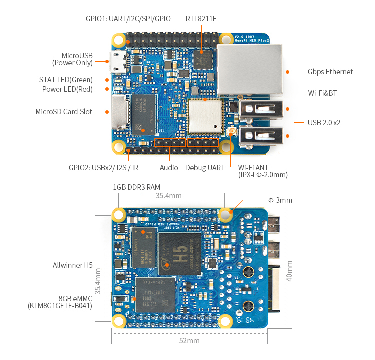
- CPU:Allwinner H5,Quad-core 64-bit high-performance Cortex A53
- DDR3 RAM :1GB
- Storage:8GB eMMC
- Network:10/100/1000M以太网口,采用RTL8211E-VB-CG传输芯片
- WiFi:802.11b/g/n
- Bluetooth:4.0 dual mode
- MicroSD Slot:1个,支持启动和储存系统
- 音频输入和输出: 5Pin, 2.0mm间距单排针
- MicroUSB:供电功能
- Debug Serial:4Pin,2.54mm间距单排针
- GPIO1:24Pin,2.51mm间距双排针,含UART、SPI、I2C、IO 等管脚资源
- GPIO2:12Pin,2.54mm间距单排针,含USB、红外接收、I2S、IO等管脚资源
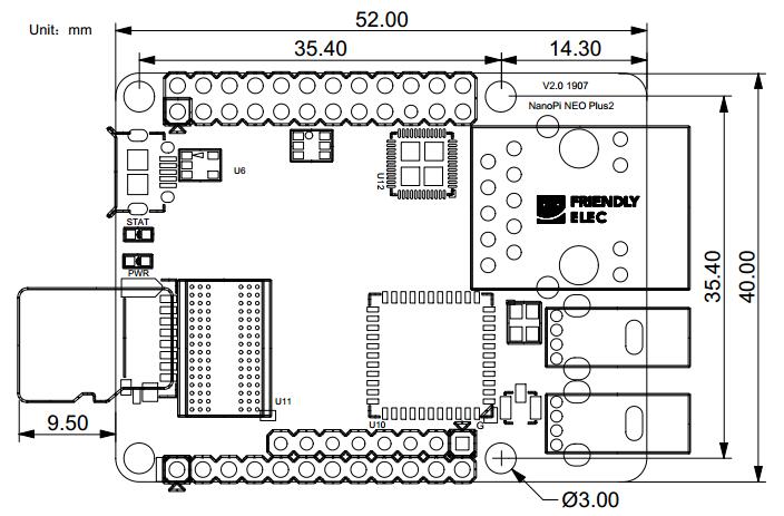
- PCB Size:40 x 52mm
- PCB Layer:6层
- Power Supply:DC 5V/2A
3 接口布局和尺寸
3.1 接口布局
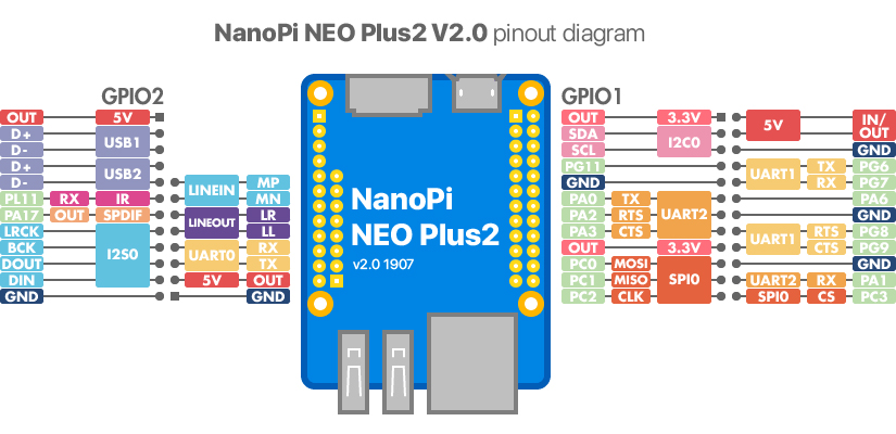
- GPIO管脚定义
Pin# Name Linux gpio Pin# Name Linux gpio 1 SYS_3.3V 2 VDD_5V 3 I2C0_SDA / GPIOA12 12 4 VDD_5V 5 I2C0_SCL / GPIOA11 11 6 GND 7 GPIOG11 203 8 UART1_TX / GPIOG6 198 9 GND 10 UART1_RX / GPIOG7 199 11 UART2_TX / GPIOA0 0 12 GPIOA6 6 13 UART2_RTS / GPIOA2 2 14 GND 15 UART2_CTS / GPIOA3 3 16 UART1_RTS / GPIOG8 200 17 SYS_3.3V 18 UART1_CTS / GPIOG9 201 19 SPI0_MOSI / GPIOC0 64 20 GND 21 SPI0_MISO / GPIOC1 65 22 UART2_RX / GPIOA1 1 23 SPI0_CLK / GPIOC2 66 24 SPI0_CS / GPIOC3 67
- USB/Audio/IR 定义
NanoPi NEO Plus2 Pin# Name Description 1 VDD_5V 5V Power Out 2 USB-DP1 USB1 DP Signal 3 USB-DM1 USB1 DM Signal 4 USB-DP2 USB2 DP Signal 5 USB-DM2 USB2 DM Signal 6 GPIOL11 / IR-RX GPIOL11 or IR Receive 7 SPDIF-OUT / GPIOA17 GPIOA17 or SPDIF-OUT 8 PCM0_SYNC / I2S0_LRC I2S / PCM Sample Rate Clock/Sync 9 PCM0_CLK / I2S0_BCK I2S / PCM Sample Rate Clock 10 PCM0_DOUT / I2S0_SDOUT I2S / PCM Serial Data Output 11 PCM0_DIN / I2S0_SDIN I2S / PCM Serial Data Input 12 GND 0V
- Audio
Pin# Name Description 1 MICIN1P Microphone Positive Input 2 MICIN1N Microphone Negative Input 3 LINEOUTR LINE-OUT Right Channel Output 4 GND 0V 5 LINEOUTL LINE-OUT Left Channel Output
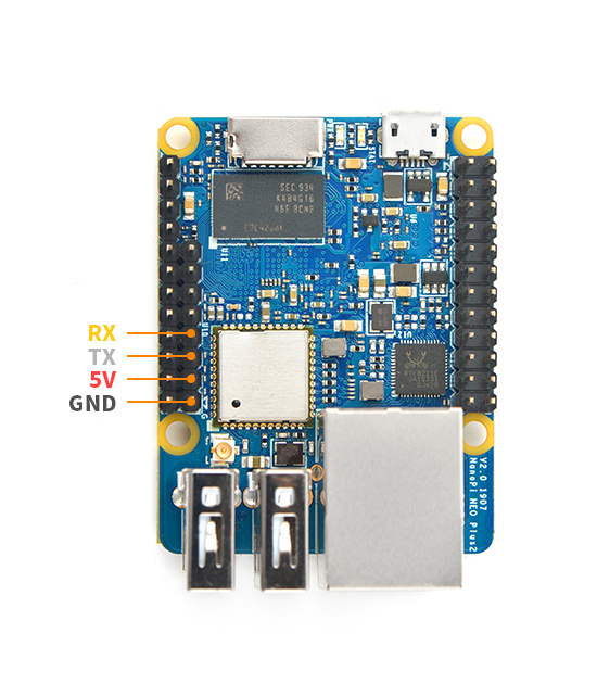
- Debug Port(UART0)
Pin# Name 1 GND 2 VDD_5V 3 UART_TXD0 / GPIOA4 4 UART_RXD0 / GPIOA5 / PWM0
- 说明
- SYS_3.3V: 3.3V电源输出
- VDD_5V: 5V电源输入/输出。输入范围:4.7~5.6V
- 全部信号引脚均为3.3V电平,输出电流为5mA,可以带动小负荷模块,io都不能带负载
- 更详细的信息请查看原理图:NanoPi-NEO-Plus2-1704-Schematic.pdf
3.2 机械尺寸
4 快速入门
4.1 准备工作
要开启你的NanoPi NEO Plus2新玩具,请先准备好以下硬件
- NanoPi NEO Plus2主板
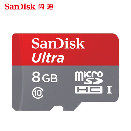
- microSD卡/TF卡: Class10或以上的 8GB SDHC卡
- 一个microUSB接口的外接电源,要求输出为5V/2A(可使用同规格的手机充电器)
- 一台电脑,需要联网,建议使用Ubuntu 16.04 64位系统
4.2 经测试使用的TF卡
制作启动NanoPi NEO Plus2的TF卡时,建议Class10或以上的 8GB SDHC卡。以下是经友善之臂测试验证过的高速TF卡:
- SanDisk闪迪 TF 8G Class10 Micro/SD 高速 TF卡:
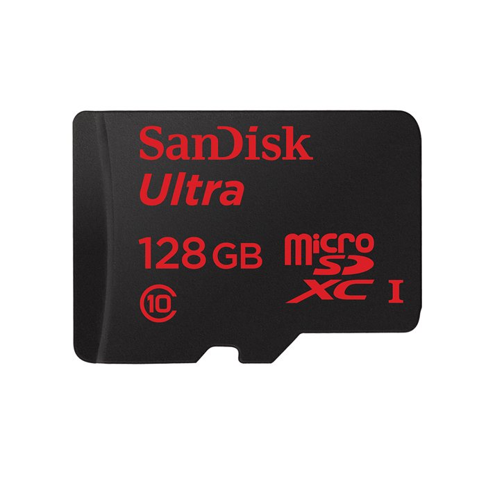
- SanDisk闪迪 TF128G 至尊高速MicroSDXC TF 128G Class10 48MB/S:
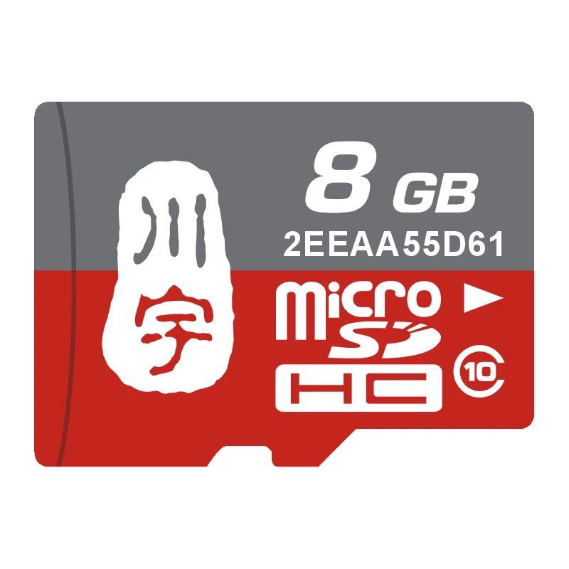
- 川宇 8G手机内存卡 8GTF卡存储卡 C10高速class10 micro SD卡:
4.3 制作一张带运行系统的TF卡
4.3.1 下载系统固件
首先访问下载地址下载需要的固件文件(officail-ROMs目录)和烧写工具(tools目录):
使用以下固件: nanopi-neo-plus2_friendlycore-xenial_4.x.y_YYYYMMDD.img.zip 基于UbuntuCore构建的FriendlyCore系统固件,使用Linux-4.x内核 nanopi-neo-plus2_debian-nas-jessie_4.x.y_YYYYMMDD.img.zip NAS系统固件,使用Linux-4.x内核,配合1-bay NAS Dock使用 nanopi-neo-plus2_ubuntu-oled_4.x.y_YYYYMMDD.img.zip OLED系统固件,使用Linux-4.x内核,配合NanoHat OLED使用 nanopi-neo-plus2_eflasher_4.x.y_YYYYMMDD.img.zip eflasher系统固件,使用Linux-4.x内核 烧写工具: win32diskimager.rar Windows平台下的系统烧写工具,Linux平台下可以用dd命令烧写系统
4.3.2 制作FriendlyCore系统TF卡
- 将Ubuntu-Core系统固件和烧写工具win32diskimager.rar分别解压,在Windows下插入TF卡(限4G及以上的卡),以管理员身份运行 win32diskimager 工具,
在win32diskimager工具的界面上,选择你的TF卡盘符,选择系统固件,点击 Write 按钮烧写即可。
- 当制作完成TF卡后,拔出TF卡插入Air的BOOT卡槽,上电启动(注意,这里需要5V/2A的供电),你可以看到绿灯常亮以及蓝灯闪烁,这时你已经成功启动Ubuntu-Core系统。
注意: Debian/Ubuntu系列的ROM都可以使用上述方法制作TF系统启动卡。
4.3.3 烧写系统到eMMC
- 将eflasher系统固件和烧写工具win32diskimager.rar分别解压,在Windows下插入TF卡(限8G及以上的卡),以管理员身份运行 win32diskimager 工具,
在win32diskimager工具的界面上,选择你的TF卡盘符,选择系统固件,点击 Write 按钮烧写即可。
- 当制作完成TF卡后,从PC上拔出TF卡然后插入NEO Plus2的BOOT卡槽,上电启动(注意,这里需要5V/2A的供电),你可以看到绿灯常亮以及蓝灯闪烁,这时你已经成功启动eflasher系统。
- 在命令行终端中通过执行下列命令进行烧写:
$ su root
$ eflasher
root用户的密码是fa,输入数字并回车选择想要安装到eMMC的系统,然后输入yes并回车确定开始烧写:

等待烧写完毕后,断电并从BOOT卡槽中取出TF卡,此时再上电就会从eMMC启动系统了。
5 Work with FriendlyCore
5.1 Introduction
FriendlyCore is a light Linux system without X-windows, based on ubuntu core, It uses the Qt-Embedded's GUI and is popular in industrial and enterprise applications.
Besides the regular Ubuntu core's features our FriendlyCore has the following additional features:
- it supports our LCDs with both capacitive touch and resistive touch(S700, X710, HD702, S430, HD101 and S70)
- it supports WiFi
- it supports Ethernet
- it supports Bluetooth and has been installed with bluez utilities
- it supports audio playing
- it supports Qt 5.10.0 EGLES and OpenGL ES1.1/2.0 (Only for S5P4418/S5P6818)
5.2 System Login
- If your board is connected to an HDMI monitor you need to use a USB mouse and keyboard.
- If you want to do kernel development you need to use a serial communication board, ie a PSU-ONECOM board, which will
For example, NanoPi-M1: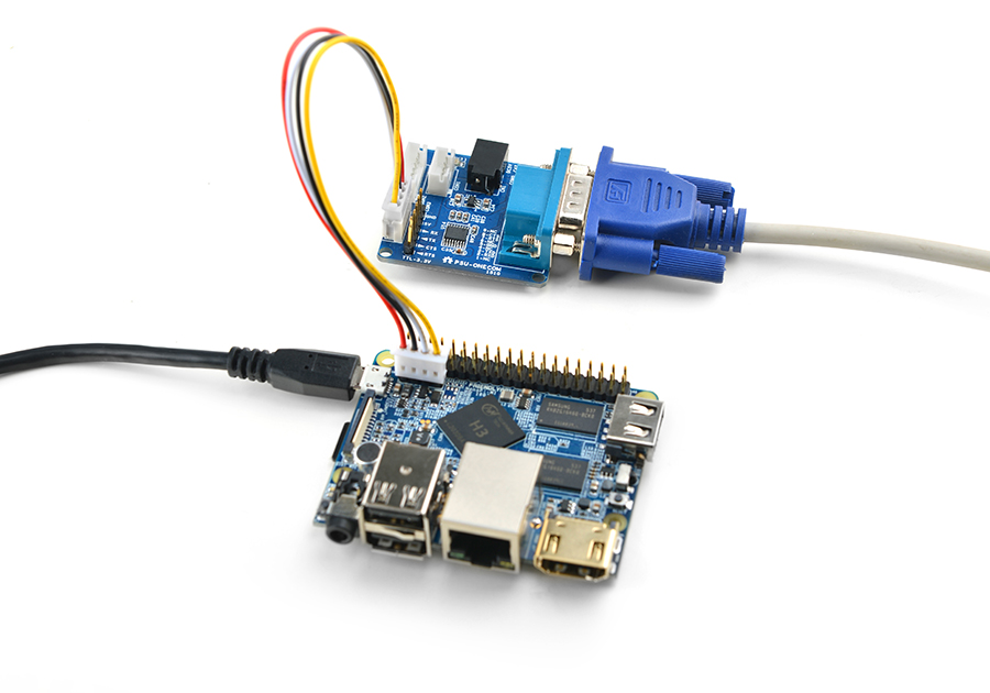
You can use a USB to Serial conversion board too.
Make sure you use a 5V/2A power to power your board from its MicroUSB port:
For example, NanoPi-NEO2: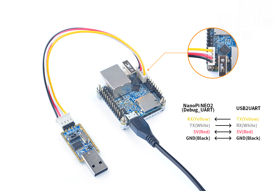
- FriendlyCore User Accounts:
Non-root User:
   User Name: pi
   Password: pi
Root:
   User Name: root
   Password: fa
The system is automatically logged in as "pi". You can do "sudo npi-config" to disable auto login.
- Update packages
$ sudo apt-get update
5.3 Configure System with npi-config
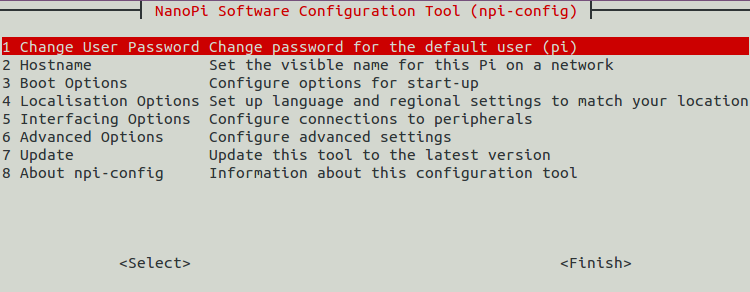
The npi-config is a commandline utility which can be used to initialize system configurations such as user password, system language, time zone, Hostname, SSH switch , Auto login and etc. Type the following command to run this utility.
$ sudo npi-config
Here is how npi-config's GUI looks like:
5.4 Develop Qt Application
Please refer to: How to Build and Install Qt Application for FriendlyELEC Boards
5.5 Setup Program to AutoRun
You can setup a program to autorun on system boot with npi-config:
sudo npi-configGo to Boot Options -> Autologin -> Qt/Embedded, select Enable and reboot.
5.6 Extend TF Card's Section
When FriendlyCore is loaded the TF card's section will be automatically extended.You can check the section's size by running the following command:
$ df -h
5.7 Transfer files using Bluetooth
Take the example of transferring files to the mobile phone. First, set your mobile phone Bluetooth to detectable status, then execute the following command to start Bluetooth search.:
hcitool scan
Search results look like:
Scanning ...
    2C:8A:72:1D:46:02   HTC6525LVW
This means that a mobile phone named HTC6525LVW is searched. We write down the MAC address in front of the phone name, and then use the sdptool command to view the Bluetooth service supported by the phone:
sdptool browser 2C:8A:72:1D:46:02
Note: Please replace the MAC address in the above command with the actual Bluetooth MAC address of the mobile phone.
This command will detail the protocols supported by Bluetooth for mobile phones. What we need to care about is a file transfer service called OBEX Object Push. Take the HTC6525LVW mobile phone as an example. The results are as follows:
Service Name: OBEX Object Push
Service RecHandle: 0x1000b
Service Class ID List:
  "OBEX Object Push" (0x1105)
Protocol Descriptor List:
  "L2CAP" (0x0100)
  "RFCOMM" (0x0003)
    Channel: 12
  "OBEX" (0x0008)
Profile Descriptor List:
  "OBEX Object Push" (0x1105)
    Version: 0x0100
As can be seen from the above information, the channel used by the OBEX Object Push service of this mobile phone is 12, we need to pass it to the obexftp command, and finally the command to initiate the file transfer request is as follows:
obexftp --nopath --noconn --uuid none --bluetooth -b 2C:8A:72:1D:46:02 -B 12 -put example.jpg
Note: Please replace the MAC address, channel and file name in the above command with the actual one.
After executing the above commands, please pay attention to the screen of the mobile phone. The mobile phone will pop up a prompt for pairing and receiving files. After confirming, the file transfer will start.
Bluetooth FAQ:
1) Bluetooth device not found on the development board, try to open Bluetooth with the following command:
rfkill unblock 02) Prompt can not find the relevant command, you can try to install related software with the following command:
apt-get install bluetooth bluez obexftp openobex-apps python-gobject ussp-push5.8 WiFi
For either an SD WiFi or a USB WiFi you can connect it to your board in the same way. The APXX series WiFi chips are SD WiFi chips. By default FriendlyElec's system supports most popular USB WiFi modules. Here is a list of the USB WiFi modules we tested:
Index Model 1 RTL8188CUS/8188EU 802.11n WLAN Adapter 2 RT2070 Wireless Adapter 3 RT2870/RT3070 Wireless Adapter 4 RTL8192CU Wireless Adapter 5 mi WiFi mt7601 6 5G USB WiFi RTL8821CU 7 5G USB WiFi RTL8812AU
You can use the NetworkManager utility to manage network. You can run "nmcli" in the commandline utility to start it. Here are the commands to start a WiFi connection:
- Change to root
$ su root
- Check device list
$ nmcli devNote: if the status of a device is "unmanaged" it means that device cannot be accessed by NetworkManager. To make it accessed you need to clear the settings under "/etc/network/interfaces" and reboot your system.
- Start WiFi
$ nmcli r wifi on- Scan Surrounding WiFi Sources
$ nmcli dev wifi- Connect to a WiFi Source
$ nmcli dev wifi connect "SSID" password "PASSWORD" ifname wlan0
The "SSID" and "PASSWORD" need to be replaced with your actual SSID and password.If you have multiple WiFi devices you need to specify the one you want to connect to a WiFi source with iface
If a connection succeeds it will be automatically setup on next system reboot.
For more details about NetworkManager refer to this link: Use NetworkManager to configure network settings
If your USB WiFi module doesn't work most likely your system doesn't have its driver. For a Debian system you can get a driver from Debian-WiFi and install it on your system. For a Ubuntu system you can install a driver by running the following commands:
$ apt-get install linux-firmware
In general all WiFi drivers are located at the "/lib/firmware" directory.
5.9 Ethernet Connection
If a board is connected to a network via Ethernet before it is powered on it will automatically obtain an IP with DHCP activated after it is powered up. If you want to set up a static IP refer to: Use NetworkManager to configure network settings。
5.10 Custom welcome message
The welcome message is printed from the script in this directory:
/etc/update-motd.d/
For example, to change the FriendlyELEC LOGO, you can change the file /etc/update-motd.d/10-header. For example, to change the LOGO to HELLO, you can change the following line:
TERM=linux toilet -f standard -F metal $BOARD_VENDOR
To:
TERM=linux toilet -f standard -F metal HELLO
5.11 Modify timezone
For exampe, change to Shanghai timezone:
sudo rm /etc/localtime
sudo ln -ls /usr/share/zoneinfo/Asia/Shanghai /etc/localtime
5.12 Set Audio Device
If your system has multiple audio devices such as HDMI-Audio, 3.5mm audio jack and I2S-Codec you can set system's default audio device by running the following commands.
- After your board is booted run the following commands to install alsa packages:
$ apt-get update
$ apt-get install libasound2
$ apt-get install alsa-base
$ apt-get install alsa-utils
- After installation is done you can list all the audio devices by running the following command. Here is a similar list you may see after you run the command:
$ aplay -l
card 0: HDMI
card 1: 3.5mm codec
card 2: I2S codec
"card 0" is HDMI-Audio, "card 1" is 3.5mm audio jack and "card 2" is I2S-Codec. You can set default audio device to HDMI-Audio by changing the "/etc/asound.conf" file as follows:
pcm.!default {
    type hw
    card 0
    device 0
}

ctl.!default {
    type hw
    card 0
}
If you change "card 0" to "card 1" the 3.5mm audio jack will be set to the default device.
Copy a .wav file to your board and test it by running the following command:
$ aplay /root/Music/test.wav
You will hear sounds from system's default audio device.
If you are using H3/H5/H2+ series board with mainline kernel, the easier way is using npi-config。
5.13 Connect to USB Camera(FA-CAM202)
The FA-CAM202 is a 200M USB camera. You can refer to <Connect DVP Camera (CAM500B) to Board> on how to connect a USB camera to a board.
You need to change the start.sh script and make sure it uses a correct /dev/videoX node. You can check your FA-CAM202's node by running the following commands:
$ apt-get install v4l-utils
$ v4l2-ctl -d /dev/video1 -D
Driver Info (not using libv4l2):
        Driver name   : uvcvideo
        Card type     : HC 3358+2100: HC 3358+2100
        Bus info      : usb-1c1b000.usb-1
	...
Information above indicates that /dev/video1 is the device node of the FA-CAM 202.
5.14 Check CPU's Working Temperature
You can get CPU's working temperature by running the following command:
$ cpu_freq
CPU0 online=1 temp=26581 governor=ondemand cur_freq=480000
CPU1 online=1 temp=26581 governor=ondemand cur_freq=480000
CPU2 online=1 temp=26581 governor=ondemand cur_freq=480000
CPU3 online=1 temp=26581 governor=ondemand cur_freq=480000
This message means there are currently four CPUs working. All of their working temperature is 26.5 degree in Celsius and each one's clock is 480MHz.
5.15 Test Watchdog
You can test watchdog by running the following commands:
$ cd /root/demo/watchdog/
$ gcc watchdog_demo.c -o watchdog_demo
$ ./watchdog_demo /dev/watchdog0 10
Set timeout: 10 seconds
Get timeout: 10 seconds
System will reboot in 10 second
System will reboot in 10 seconds.
5.16 Test Infrared Receiver
Note: Please Check your board if IR receiver exist.
By default the infrared function is disabled you can enable it by using the npi-config utility:
$ npi-config
    6 Advanced Options     Configure advanced settings
        A8 IR              Enable/Disable IR
            ir Enable/Disable ir[enabled]
Reboot your system and test its infrared function by running the following commands:
$ apt-get install ir-keytable
$ echo "+rc-5 +nec +rc-6 +jvc +sony +rc-5-sz +sanyo +sharp +mce_kbd +xmp" > /sys/class/rc/rc0/protocols   # Enable infrared
$ ir-keytable -t
Testing events. Please, press CTRL-C to abort.
"ir-keytable -t" is used to check whether the receiver receives infrared signals. You can use a remote control to send infrared signals to the receiver. If it works you will see similar messages as follows:
1522404275.767215: event type EV_MSC(0x04): scancode = 0xe0e43
1522404275.767215: event type EV_SYN(0x00).
1522404278.911267: event type EV_MSC(0x04): scancode = 0xe0e42
1522404278.911267: event type EV_SYN(0x00).
5.17 Read CHIP ID
As for Allwinner H2+/H3/H5/ SoCs each of these CPUs has an internal 16-btye CHIP ID which can be read by running the following commands in the Linux-4.14 kernel:
$ apt-get install bsdmainutils
$ hexdump /sys/bus/nvmem/devices/sunxi-sid0/nvmem
0000000 8082 0447 0064 04c3 3650 ce0a 1e28 2202
0000010 0002 0000 0000 0000 0000 0000 0000 0000
0000020 0000 0000 0000 0000 0000 0000 0000 0000
0000030 0000 0008 0508 0000 0000 0000 0000 0000
0000040 0000 0000 0000 0000 0000 0000 0000 0000
"8082 0447 0064 04c3 3650 ce0a 1e28 2202" is the 16-byte CHIP ID.
5.18 Access GPIO Pins/Wirings with WiringNP
The wiringPi library was initially developed by Gordon Henderson in C. It contains libraries to access GPIO, I2C, SPI, UART, PWM and etc. The wiringPi library contains various libraries, header files and a commandline utility:gpio. The gpio utility can be used to read and write GPIO pins.
FriendlyElec integrated this utility in FriendlyCore system allowing users to easily access GPIO pins. For more details refer to WiringNP WiringNP
5.19 Run Qt Demo
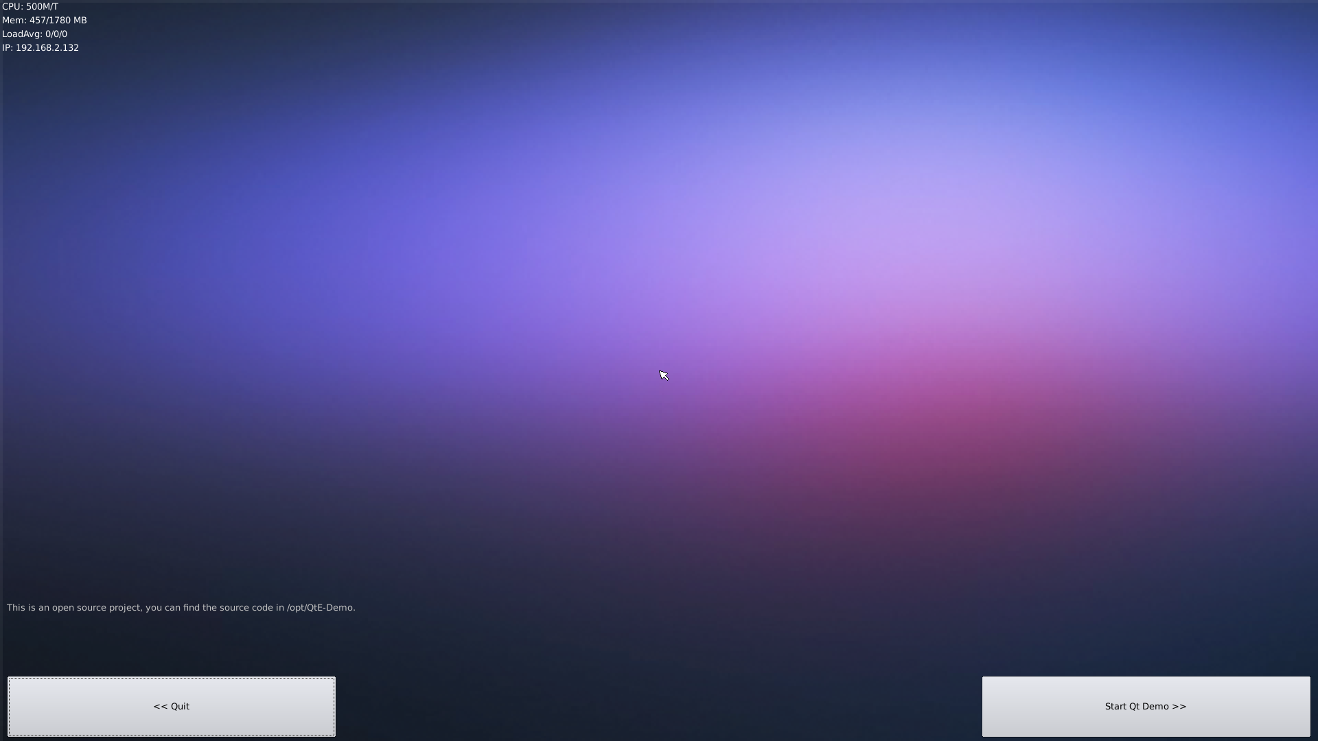
Run the following command
$ sudo /opt/QtE-Demo/run.sh
Here is what you expect to observe. This is an open source Qt Demo:
5.20 How to install and use docker (for arm64 system)
5.20.1 How to Install Docker
Run the following commands:
sudo apt-get update
sudo apt-get install docker.io
5.20.2 Test Docker installation
Test that your installation works by running the simple docker image:
git clone https://github.com/friendlyarm/debian-jessie-arm-docker
cd debian-jessie-arm-docker
./rebuild-image.sh
./run.sh
5.21 播放和录制音频
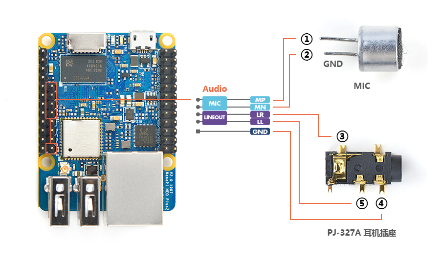
NEO Plus2只提供了音频硬件接口(2.0mm 5pin 排针),引脚的定义如下:
Pin# Name Description 1 MICIN1P Microphone Positive Input 2 MICIN1N Microphone Negative Input 3 LINEOUTR LINE-OUT Right Channel Output 4 GND 地 5 LINEOUTL LINE-OUT Left Channel Output
用户需自行转接音频设备,参考下图:
只有在已外接音频设备的前提下,才可以进行下列步骤测试播放和录制音频。
查看系统里的声卡设备:
$ aplay -l
**** List of PLAYBACK Hardware Devices ****
card 0: Codec [H3 Audio Codec], device 0: CDC PCM Codec-0 []
  Subdevices: 1/1
  Subdevice #0: subdevice #0
全志H5和H3这两款CPU内部都自带了同一个codec设备,在主线内核中被命名为[H3 Audio Codec]。
播放音频:
$ aplay /root/Music/test.wav -D plughw:0
录制音频:
$ arecord -f cd -d 5 test.wav
6 如何编译FriendlyCore系统
6.1 使用开源社区主线BSP
NEO Plus2现已支持使用64位Linux内核,并使用64位Ubuntu Core 16.04,关于H5芯片系列开发板使用主线U-boot和Linux-4.x.y的方法,请参考维基:Mainline U-boot & Linux
7 使用扩展配件及编程示例
7.1 使用1-bay NAS Dock DIY自已的NAS服务器
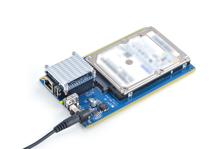
1-bay NAS Dock是一个用于搭建迷你、小巧的桌上型NAS(Network Attached Storage:网络附属存储)设备的扩展底板,它采用了高速稳定的专业级USB 3.0 to SATA转换芯片(JSM568), 可直接安装使用2.5寸小硬盘,并采用TI公司DC-DC芯片实现稳定可靠的12V-5V电源转换,支持板载RTC时钟备份电池;我们还基于最新主线内核Linux-4.11和Debian-Jessie 为其移植了开源NAS软件系统OpenMediaVault,另外配上我们专门为其定制的精致喷砂金属铝外壳,就能够快速的搭建属于你的专用数据存储服务器,详见:1-bay NAS Dock v1.2 for NanoPi NEO/NEO2
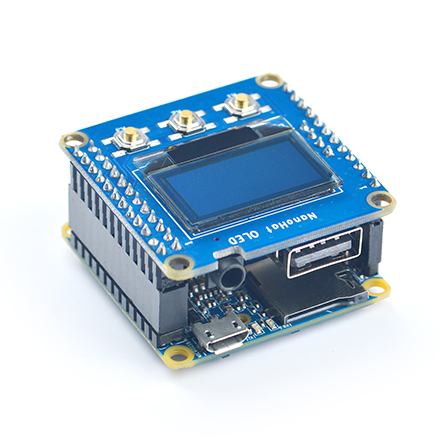
7.2 使用Python编程操作NanoHat OLED扩展板
NanoHat OLED是一款精致小巧的单色OLED显示屏,带3个按键,我们不仅提供了源代码级驱动,而且为您展现了一个简单实用的Shell界面, 通过它你可以查看系统时间,系统运行状态,以及关机等操作;你还可以下载所有源代码自行修改编译,设计自己喜欢的界面; 配上我们专门为其定制的全金属铝外壳,相信你一定会爱不释手!详见:NanoHat OLED
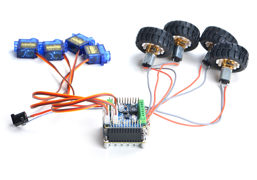
7.3 使用Python编程控制NanoHat Motor 电机驱动模块
该模块可驱动四个5V PWM舵机模块和四个12V直流电机或者两个12V四线步进电机,详见:NanoHat Motor
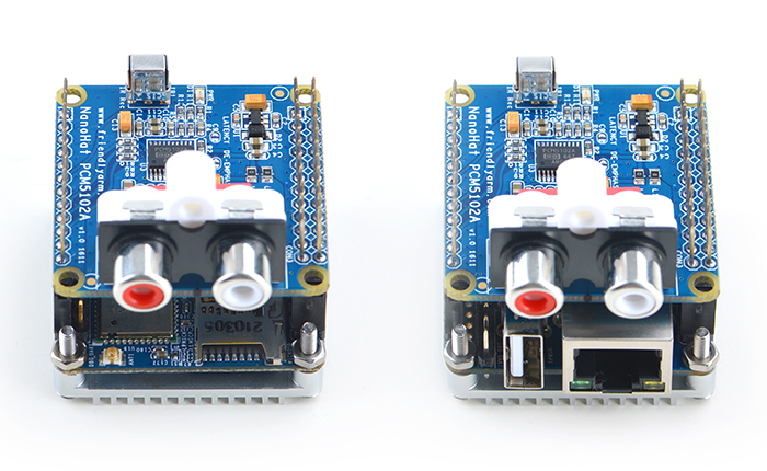
7.4 使用NanoHat PCM5102A 数字音频解码模块
NanoHat PCM5102A采用了TI公司专业的立体声DAC音频芯片PCM5102A,为您提供数字音频信号完美还原的音乐盛宴, 详见:NanoHat PCM5102A
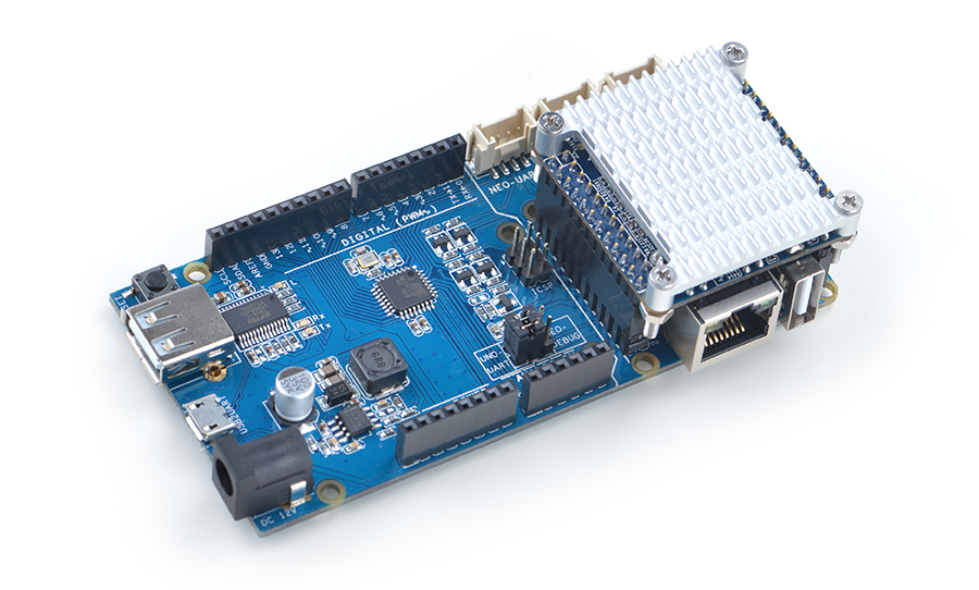
7.5 完全兼容的Arduino的UNO Dock扩展板
UNO Dock本身就是一个Arduino UNO,你可以使用Arduino IDE开发下载运行所有Arduino工程项目;它还是NanoPi NEO的扩展坞,不仅为其提供稳定可靠的电源输入,还可以使用Python编程控制Arduino配件,借助强大的Ubuntu生态系统,快速把你的Arduino项目送上云端,详见:UNO Dock for NanoPi NEO v1.0
7.6 Power Dock 高效的电源转换模块
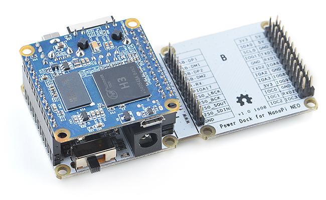
Power Dock for NanoPi NEO是一个高效的电源转换模块,能为用电设备提供稳定可靠的供电, 详见:Power Dock for NanoPi NEO
7.7 NanoHat Proto 可堆叠的面包板模块
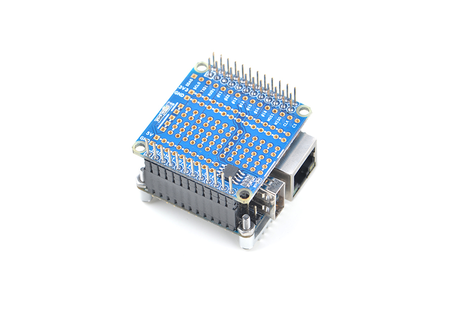
NanoHat Proto是一个功能高度自由的模块, 板载EEPROM,详见:NanoHat Proto
7.8 Matrix - 2'8 SPI Key TFT显示模块
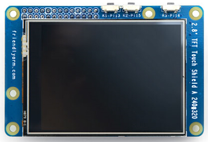
Matrix-2'8_SPI_Key_TFT模块是一款2.8英寸的TFT 触摸LCD,模块采用ST7789S驱动IC和XPT2046电阻式触摸IC,屏幕分辨率为240*320,采用SPI控制接口,模块还包含3个独立按键,可根据需要自定义功能。详见:Matrix - 2'8 SPI Key TFT
8 3D 打印外壳
9 资源链接
9.1 手册原理图等开发资料
- Schematic: NanoPi-NEO-Plus2-1704-Schematic.pdf
- Dimensions: NanoPi-NEO-Plus2-1704_pcb的dxf文件
- H5 Datasheet: Allwinner_H5_Datasheet_V1.0.pdf
