Difference between revisions of "Matrix - Potentiometer"
(→下载Matrix源码) |
(→与NanoPi 2连接使用) |
||
| Line 50: | Line 50: | ||
If this is successful a "matrix" directory will be generated, which will contain all the matrix modules' code samples.<br> | If this is successful a "matrix" directory will be generated, which will contain all the matrix modules' code samples.<br> | ||
| − | == | + | ==Connect to NanoPi 2== |
| − | === | + | ===Hardware Connection=== |
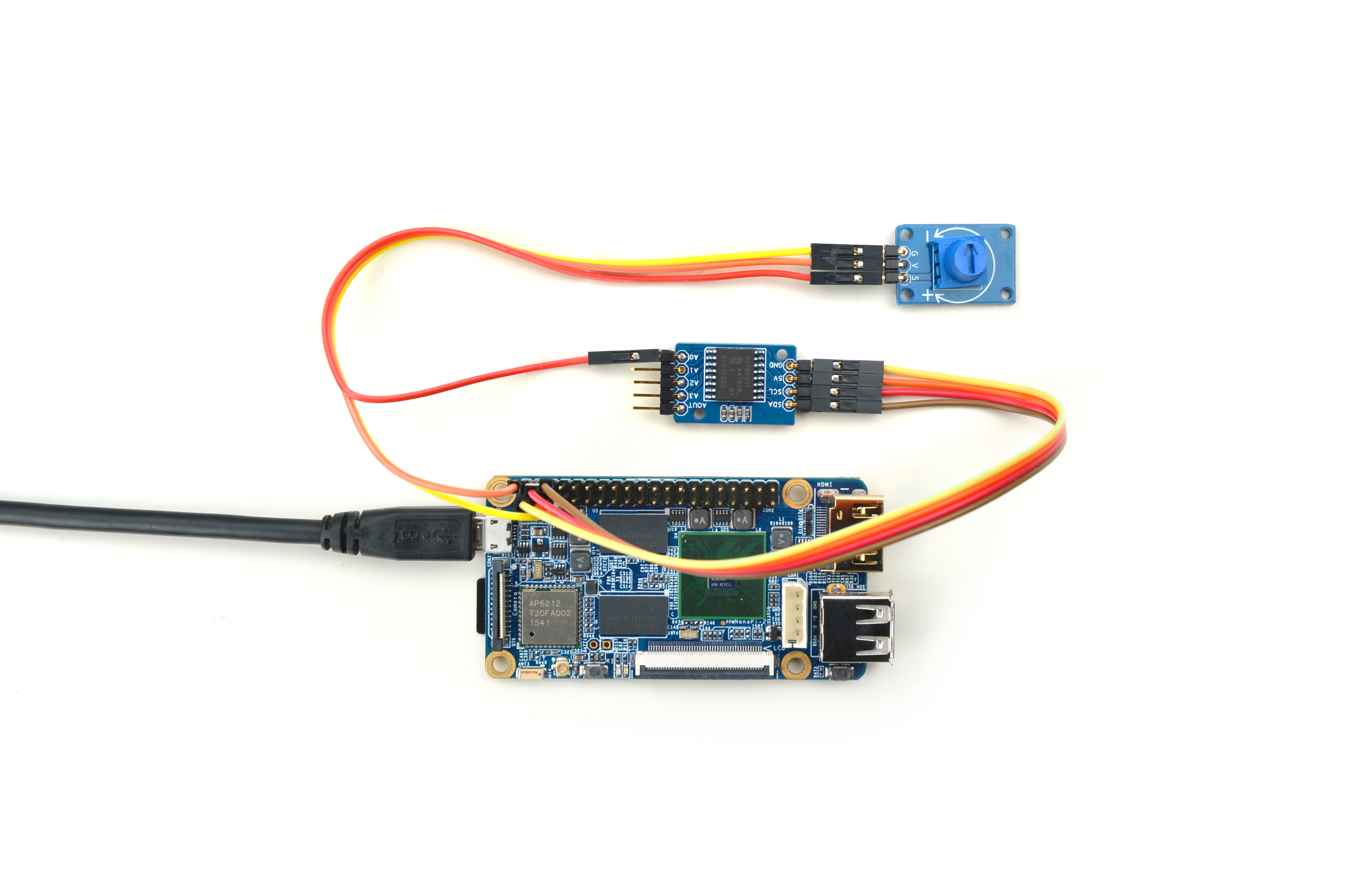
| − | + | Please refer to the following connection diagram to connect the Matrix-Potentiometer to the NanoPi 2:<br> | |
[[File:Matrix-Potentiometer.jpg|frameless|600px|Matrix-Potentiometer]] | [[File:Matrix-Potentiometer.jpg|frameless|600px|Matrix-Potentiometer]] | ||
| − | + | Connection Details: | |
{| class="wikitable" | {| class="wikitable" | ||
|- | |- | ||
| Line 79: | Line 79: | ||
|S || Matrix-Analog_to_Digital_Converter A0 | |S || Matrix-Analog_to_Digital_Converter A0 | ||
|} | |} | ||
| − | + | This module's output signals are analog signals. You can use our Matrix-Analog_to_Digital_Converter to convert them to digital signals.<br> | |
| − | + | Please connect the Matrix-Analog_to_Digital_Converter to the NanoPi 2 and then connect Pin S of the Matrix-Photoresistor's pin header to Matrix-Analog_to_Digital_Converter's A0.<br> | |
| − | + | For more details about the Matrix-Analog_to_Digital_Converter module please refer to wiki: [[Matrix_-_Analog_to_Digital_Converter]].<br> | |
===编译测试程序=== | ===编译测试程序=== | ||
Revision as of 11:31, 6 January 2016
English
Contents
1 Introduction
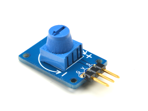
- The Matrix-Potentiometer module is a Potentiometer module. It can be used in audio control, motion control, transducers, computation and etc.
- 3 Pin 2.54mm spacing pin header, V is supply voltage, G is ground and S is output analog signal. Users can convert output analog signals to digital signals via ADC conversion.
- Output Voltage: 0 ~ Vcc
2 Features
- GPIO
- Small
- 2.54mm spacing pin header
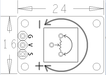
- PCB Dimension(mm): 8 x 24
- Pin Description:
| Pin | Description |
| S | Analog GPIO |
| V | Supply Voltage 5V |
| G | Ground |
3 Basic Device Operation
- A potentiometer is a three-terminal resistor with a sliding or rotating contact that forms an adjustable voltage divider.If only two terminals are used, one end and the wiper, it acts as a variable resistor or rheostat.
- This module mainly contains a potentiometer where the resistance changes with changes between the contact and one end terminal.
4 Download Matrix Source Code
All the matrix modules' code samples are open source. They are maintained on GitHub :https://github.com/friendlyarm/matrix.git
Each branch in this hub contains the matrix modules' code samples for a board that the matrix modules can work with.
- The matrix-nanopi branch contains the matrix modules' code samples for the NanoPi;
- The matrix-nanopi2 branch contains the matrix modules' code samples for the NanoPi 2;
- The matrix-tiny4412 branch contains the matrix modules' code samples for the Tiny4412;
- The matrix-raspberrypi branch contains the matrix modules' code samples for the RaspberryPi
Please follow the steps below to get the source code:
Install the git utility on a PC running Ubuntu14.04
$ sudo apt-get install git
Clone the matrix code from GitHub
$ git clone https://github.com/friendlyarm/matrix.git
If this is successful a "matrix" directory will be generated, which will contain all the matrix modules' code samples.
5 Connect to NanoPi 2
5.1 Hardware Connection
Please refer to the following connection diagram to connect the Matrix-Potentiometer to the NanoPi 2:

Connection Details:
| Matrix-Analog_to_Digital_Converter | NanoPi 2 |
| SDA | Pin3 |
| SCL | Pin5 |
| 5V | Pin4 |
| GND | Pin6 |
| Matrix-Potentiometer | |
| GND | NanoPi 2 Pin9 |
| 5V | NanoPi 2 Pin2 |
| S | Matrix-Analog_to_Digital_Converter A0 |
This module's output signals are analog signals. You can use our Matrix-Analog_to_Digital_Converter to convert them to digital signals.
Please connect the Matrix-Analog_to_Digital_Converter to the NanoPi 2 and then connect Pin S of the Matrix-Photoresistor's pin header to Matrix-Analog_to_Digital_Converter's A0.
For more details about the Matrix-Analog_to_Digital_Converter module please refer to wiki: Matrix_-_Analog_to_Digital_Converter.
5.2 编译测试程序
进入Matrix代码仓库,切换到nanopi2分支
$ cd matrix
$ git checkout nanopi2
编译Matrix配件代码
$ make CROSS_COMPILE=arm-linux- clean
$ make CROSS_COMPILE=arm-linux-
$ make CROSS_COMPILE=arm-linux- install
注意:请确保你的主机PC当前使用的交叉编译器为NanoPi 2配套的arm-linux-gcc-4.9.3。
编译成功后库文件位于install/lib目录下,而测试程序则位于install/usr/bin目录下,模块Matrix-Potentiometer对应的测试程序为matrix-adc。
硬件驱动模块位于modules目录下,对应的驱动源码都包含在在NanoPi 2的Linux内核仓库里:https://github.com/friendlyarm/linux-3.4.y.git
5.3 运行测试程序
将带有Debian系统的SD卡插入一台运行Linux的电脑,可以挂载SD卡上的boot和rootfs分区。
假设rootfs分区的挂载路径为/media/rootfs,执行以下命令将Matrix的硬件驱动、库文件和测试程序拷贝到NanoPi 2的文件系统上。
$ cp modules /media/rootfs/ -r
$ cp install/lib/* /media/rootfs/lib/ -d
$ cp install/usr/bin/* /media/rootfs/usr/bin/
将SD卡重新插入NanoPi 2,上电启动,在Debian的shell终端中执行以下命令加载硬件驱动。
$ cd /modules
$ insmod pcf8591.ko
运行模块Matrix-Potentiometer的测试程序。
$ matrix-adc5.4 代码展示
int main(int argc, char ** argv)
{
    int i = 0;
    int value = 0;
    int channel = 0;

    if (argc == 2) {
        channel = atoi(argv[1]);
    }

    for (i=0; i<ADC_READ_TIMES; i++) {
        if (pcf8591Read(channel, &value) != -1) {
            printf("channel%d value=%d\n", channel, value);
        } else {
            printf("Fail to get channel%d value\n", channel);
        }
        usleep(10000);
    }
    return 0;
}


