Difference between revisions of "NanoPi NEO Plus2"
(→接口布局和尺寸) |
(→介绍) |
||
| Line 8: | Line 8: | ||
---> | ---> | ||
| − | == | + | ==Introduction== |
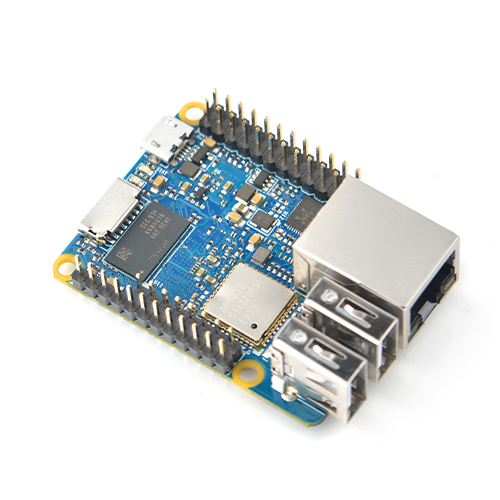
[[File:NanoPi NEO Plus2-1.jpg|thumb|frameless|300px|Overview]] | [[File:NanoPi NEO Plus2-1.jpg|thumb|frameless|300px|Overview]] | ||
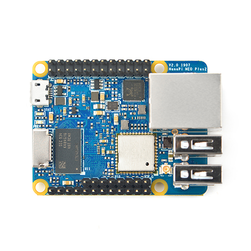
[[File:NanoPi NEO Plus2-2.jpg|thumb|frameless|300px|Front]] | [[File:NanoPi NEO Plus2-2.jpg|thumb|frameless|300px|Front]] | ||
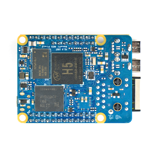
[[File:NanoPi NEO Plus2-3.jpg|thumb|frameless|300px|Back]] | [[File:NanoPi NEO Plus2-3.jpg|thumb|frameless|300px|Back]] | ||
| − | * NanoPi NEO | + | * The NanoPi NEO Plus2 is another Allwinner based ARM board developed by FriendlyElec. It uses Allwinner's 64-bit quad-core A53 SoC with hexa-core Mali450 GPU and features 1GB of DDR3 RAM and 8GB eMMC. |
| − | * NanoPi NEO | + | * With a small size of only 40 x 52mm the NanoPi NEO Plus2 has rich on-board resources: AP6212A WiFi & Bluetooth module, Gbps Ethernet and two USB hosts. It supports system-boot from a MicroSD card. |
| − | * NanoPi NEO | + | * The NanoPi NEO Plus2 has a carefully designed power system and 6-layer PCB layout. These features enhance the board's heat dissipation. |
| + | * The NanoPi NEO Plus2 meets popular IOT applications requirements for small size, high-speed and large throughput data transmission and high performance computing. | ||
==Hardware Spec== | ==Hardware Spec== | ||
Revision as of 01:44, 30 May 2017
Contents
1 Introduction
- The NanoPi NEO Plus2 is another Allwinner based ARM board developed by FriendlyElec. It uses Allwinner's 64-bit quad-core A53 SoC with hexa-core Mali450 GPU and features 1GB of DDR3 RAM and 8GB eMMC.
- With a small size of only 40 x 52mm the NanoPi NEO Plus2 has rich on-board resources: AP6212A WiFi & Bluetooth module, Gbps Ethernet and two USB hosts. It supports system-boot from a MicroSD card.
- The NanoPi NEO Plus2 has a carefully designed power system and 6-layer PCB layout. These features enhance the board's heat dissipation.
- The NanoPi NEO Plus2 meets popular IOT applications requirements for small size, high-speed and large throughput data transmission and high performance computing.
2 Hardware Spec
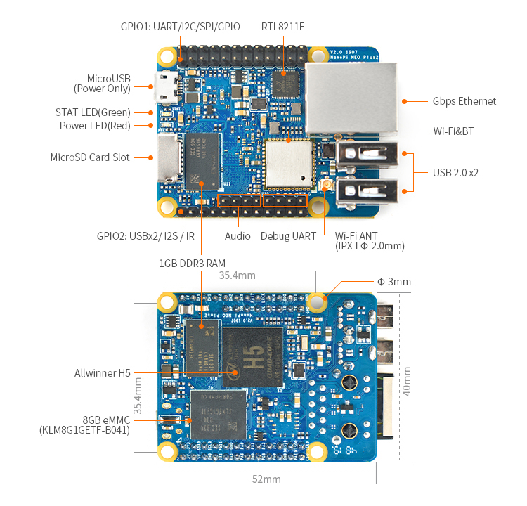
- SoC: Allwinner H5,Quad-core 64-bit high-performance Cortex A53
- DDR3 RAM:1GB
- Storage: 8GB eMMC
- Network: 10/100/1000M Ethernet based on RTL8211E-VB-CG
- WiFi: 802.11b/g/n
- Bluetooth: 4.0 dual mode
- MicroSD Slot: 1 x Slot. It supports system booting or is used to hold a storage card
- Audio Input/Output: 5-Pin, 2.0mm pitch pin-header
- MicroUSB: power input
- Debug Serial: 4Pin, 2.54mm pitch pin-header
- GPIO1:24Pin, 2.51mm pitch double-row pin-header containing UART, SPI, I2C and IO
- GPIO2:12Pin, 2.54mm pitch pin-header containing USB, IR receiver,I2S and IO
- Power Supply: DC 5V/2A
- PCB Dimension: 40 x 52mm
- PCB Layer: 6-Layer
3 Software Features
3.1 UbuntuCore
- mainline kernel: Linux-4.x.y
- npi-config: system configuration utility for setting passwords, language, timezone, hostname, SSH and auto-login.
- auto-login with user account "pi" with access to npi-config
- supports Gbps Ethernet
- supports WiFi and Bluetooth
- supports FriendlyElec's FA-CAM202 USB camera
- supports audio recording and playing
4 Diagram, Layout and Dimension
4.1 Layout
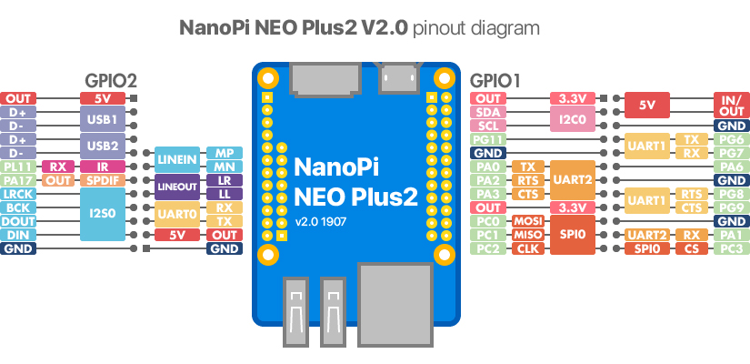
- GPIO Pin Description
Pin# Name Linux gpio Pin# Name Linux gpio 1 SYS_3.3V 2 VDD_5V 3 I2C0_SDA / GPIOA12 12 4 VDD_5V 5 I2C0_SCL / GPIOA11 11 6 GND 7 GPIOG11 203 8 UART1_TX / GPIOG6 198 9 GND 10 UART1_RX / GPIOG7 199 11 UART2_TX / GPIOA0 0 12 GPIOA6 6 13 UART2_RTS / GPIOA2 2 14 GND 15 UART2_CTS / GPIOA3 3 16 UART1_RTS / GPIOG8 200 17 SYS_3.3V 18 UART1_CTS / GPIOG9 201 19 SPI0_MOSI / GPIOC0 64 20 GND 21 SPI0_MISO / GPIOC1 65 22 UART2_RX / GPIOA1 1 23 SPI0_CLK / GPIOC2 66 24 SPI0_CS / GPIOC3 67
- USB/Audio/IR Pin Description
NanoPi NEO Plus2 Pin# Name Description 1 VDD_5V 5V Power Out 2 USB-DP1 USB1 DP Signal 3 USB-DM1 USB1 DM Signal 4 USB-DP2 USB2 DP Signal 5 USB-DM2 USB2 DM Signal 6 GPIOL11 / IR-RX GPIOL11 or IR Receive 7 SPDIF-OUT / GPIOA17 GPIOA17 or SPDIF-OUT 8 PCM0_SYNC / I2S0_LRC I2S / PCM Sample Rate Clock/Sync 9 PCM0_CLK / I2S0_BCK I2S / PCM Sample Rate Clock 10 PCM0_DOUT / I2S0_SDOUT I2S / PCM Serial Data Output 11 PCM0_DIN / I2S0_SDIN I2S / PCM Serial Data Input 12 GND 0V
- Audio
Pin# Name Description 1 MICIN1P Microphone Positive Input 2 MICIN1N Microphone Negative Input 3 LINEOUTR LINE-OUT Right Channel Output 4 GND 0V 5 LINEOUTL LINE-OUT Left Channel Output
- Debug Port(UART0)
Pin# Name 1 GND 2 VDD_5V 3 UART_TXD0 / GPIOA4 4 UART_RXD0 / GPIOA5 / PWM0
- Note:
- SYS_3.3V: 3.3V power output
- VVDD_5V: 5V power input/output. The input range is 4.7V ~ 5.6V
- All pins are 3.3V, output current is 5mA
- For more details refer to the document: NanoPi-NEO-Plus2-1704-Schematic.pdf
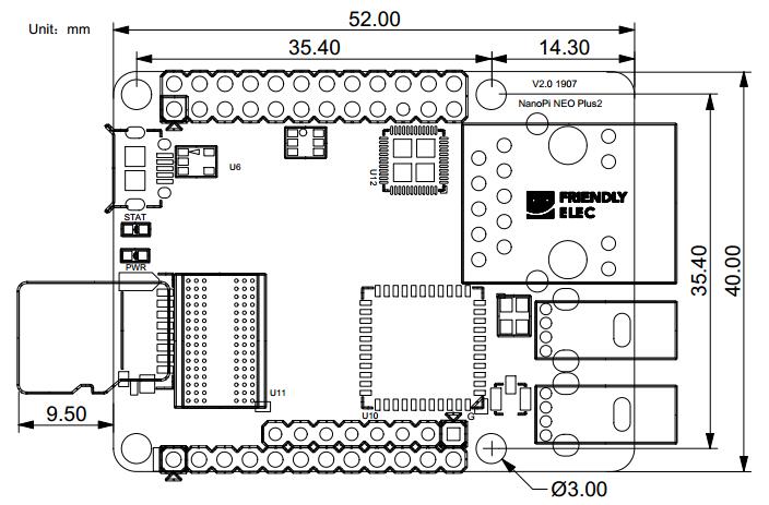
4.2 Dimensional Diagram
- For more details refer to: [Dimensions_NanoPi-NEO-Plus2-1704]
5 快速入门
5.1 准备工作
要开启你的NanoPi NEO Plus2新玩具,请先准备好以下硬件
- NanoPi NEO Plus2主板
- microSD卡/TF卡: Class10或以上的 8GB SDHC卡
- 一个microUSB接口的外接电源,要求输出为5V/2A(可使用同规格的手机充电器)
- 一台电脑,需要联网,建议使用Ubuntu 14.04 64位系统
5.2 经测试使用的TF卡
制作启动NanoPi NEO Plus2的TF卡时,建议Class10或以上的 8GB SDHC卡。以下是经友善之臂测试验证过的高速TF卡:
- SanDisk闪迪 TF 8G Class10 Micro/SD 高速 TF卡:
- SanDisk闪迪 TF128G 至尊高速MicroSDXC TF 128G Class10 48MB/S:
- 川宇 8G手机内存卡 8GTF卡存储卡 C10高速class10 micro SD卡:
5.3 制作一张带运行系统的TF卡
5.3.1 下载系统固件
首先访问下载地址下载需要的固件文件(officail-ROMs目录)和烧写工具(tools目录):
使用以下固件: nanopi-neo-plus2_ubuntu-core-xenial_4.x.y_YYYYMMDD.img.zip Ubuntu-Core with Qt-Embedded系统固件,使用Linux-4.x内核 nanopi-neo-plus2_debian-nas-jessie_4.x.y_YYYYMMDD.img.zip NAS系统固件,使用Linux-4.x内核,配合1-bay NAS Dock使用 nanopi-neo-plus2_ubuntu-oled_4.x.y_YYYYMMDD.img.zip OLED系统固件,使用Linux-4.x内核,配合NanoHat OLED使用 nanopi-neo-plus2_eflasher_4.x.y_YYYYMMDD.img.zip eflasher系统固件,使用Linux-4.x内核 烧写工具: win32diskimager.rar Windows平台下的系统烧写工具,Linux平台下可以用dd命令烧写系统
5.3.2 制作Ubuntu-Core with Qt-Embedded系统TF卡
将固件nanopi-neo-plus2_ubuntu-core-xenial_4.x.y_YYYYMMDD.img.zip和烧写工具win32diskimager.rar分别解压,在Windows下插入TF卡(限4G及以上的卡),以管理员身份运行 win32diskimager 工具,
在win32diskimager工具的界面上,选择你的TF卡盘符,选择系统固件,点击 Write 按钮烧写即可。烧写完成后,将制作好TF卡插入NanoPi NEO Plus2,使用USB供电(5V/2A),
NanoPi NEO Plus2会上电自动开机,看到板上的蓝色LED闪烁,这说明系统已经开始启动了。
5.3.3 烧写系统到eMMC
- 将固件nanopi-neo-plus2_eflasher_4.x.y_YYYYMMDD.img.zip和烧写工具win32diskimager.rar分别解压,在Windows下插入TF卡(限8G及以上的卡),以管理员身份运行 win32diskimager 工具,
在win32diskimager工具的界面上,选择你的TF卡盘符,选择系统固件,点击 Write 按钮烧写即可。
- 当制作完成TF卡后,拔出TF卡插入Air的BOOT卡槽,上电启动(注意,这里需要5V/2A的供电),你可以看到绿灯常亮以及蓝灯闪烁,这时你已经成功启动eflasher系统。
- 在命令行终端中通过执行下列命令进行烧写:
$ eflasher输入数字并回车选择想要安装到eMMC的系统,然后输入yes并回车确定开始烧写。等待烧写完毕后,断电并从BOOT卡槽中取出TF卡,此时再上电就会从eMMC启动系统了。
6 Ubuntu-Core with Qt-Embedded系统的使用
6.1 运行Ubuntu-Core with Qt-Embedded系统
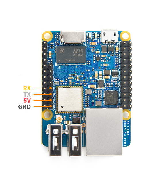
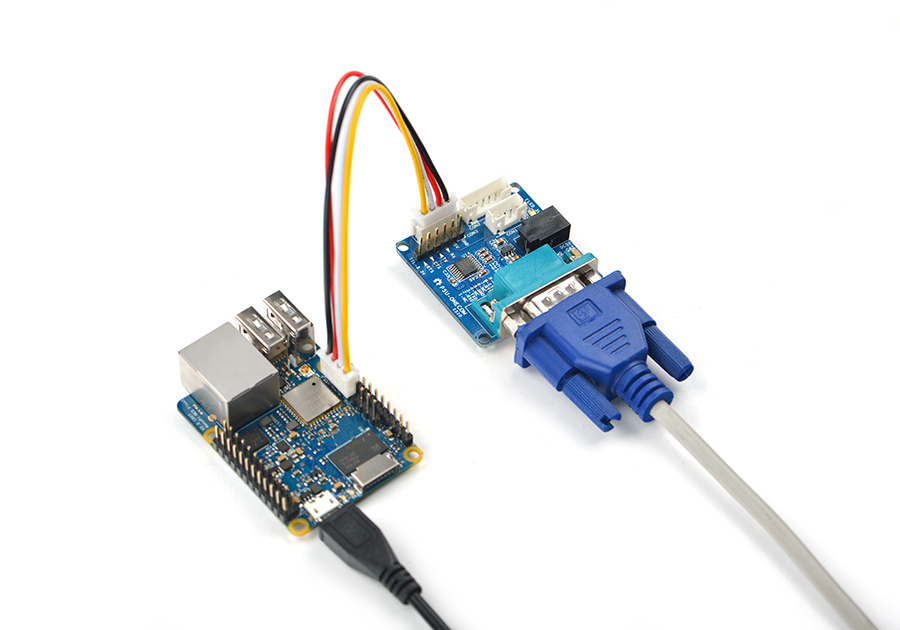
- 如果您需要进行内核开发,你最好选购一个串口配件,连接了串口,则可以通过串口终端对NanoPi NEO Plus2进行操作。以下是串口配件的接法,接上串口,即可调试。接上串口后你可以选择从串口模块的DC口或者从NanoPi NEO Plus2的MicroUSB口进行供电:
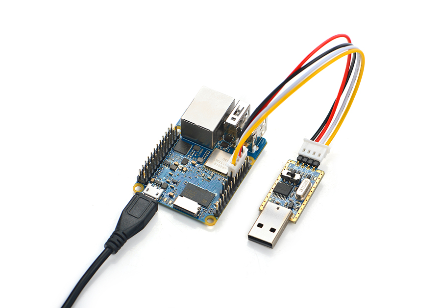
也可以使用USB转串口模块调试,请注意需要使用5V/2A电源从NanoPi NEO Plus2的MicroUSB口给NEO Plus2供电:
- Ubuntu-Core默认帐户:
普通用户:
   用户名: pi
   密码: pi
Root用户:
   用户名: root
   密码: fa
默认会以 pi 用户自动登录,你可以使用 sudo npi-config 命令取消自动登录。
- 更新软件包:
sudo apt-get update
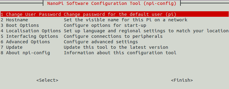
6.2 使用npi-config配置系统
npi-config是一个命令行下的系统配置工具,可以对系统进行一些初始化的配置,可配置的项目包括:用户密码、系统语言、时区、Hostname、SSH开关、自动登录选项等,在命令行执行以下命令即可进入:
sudo npi-config
6.3 连接有线网络
NanoPi NEO Plus2在加电开机前如果已正确的连接网线,则系统启动时会自动获取IP地址,如果没有连接网线、没有DHCP服务或是其它网络问题,则会导致获取IP地址失败,同时系统启动会因此等待约15~60秒的时间。 手动获取IP地址
dhclient eth0
6.4 SSH登录
NanoPi NEO Plus2没有任何图形界面输出的接口,如果你没有串口模块,可以通过SSH协议登录NanoPi NEO Plus2。假设通过路由器查看到NanoPi NEO Plus2的IP地址为192.168.1.230,你可以在PC机上执行如下命令登录NanoPi NEO Plus2:
ssh root@192.168.1.230
密码为fa。
6.5 扩展TF卡文件系统
第一次启动系统时,系统会自动扩展文件系统分区,请耐心等待,TF卡的容量越大,需要等待的时间越长,进入系统后执行下列命令查看文件系统分区大小:
df -h
6.6 连接无线网络
NanoPi NEO Plus使用无线网络或者蓝牙的时候,需要接上天线使用。以下是 NEO Plus2连接使用IPX天线的图片:
NanoPi NEO Plus2 上电启动后,通过串口登录到系统,敲入以下命令可以查看到系统是否识别到 WiFi,如果出现“wlan0”,则证明WiFi已被识别到:
sudo ifconfig -a
用vi打开文件 /etc/wpa_supplicant/wpa_supplicant.conf:
sudo vi /etc/wpa_supplicant/wpa_supplicant.conf
在文件末尾填入路由器信息如下所示:
network={
        ssid="YourWiFiESSID"
        psk="YourWiFiPassword"
}
其中,YourWiFiESSID和YourWiFiPassword请替换成你要连接的无线AP名称和密码。
保存退出后,执行以下命令即可连接WiFi:
$ sudo ifdown wlan0
$ sudo ifup wlan0
如果你的WiFi密码中有特殊字符,或者你不希望明文存放密码,你可以使用wpa_passphrase命令为WiFi密码生成一个密钥(psk),用密钥来代替密码 ,在命令行下,可输入以下命令生成密钥:
$ sudo wpa_passphrase YourWiFiESSID
在提示输入密码时,输入你的WiFi密码,再打开 /etc/wpa_supplicant/wpa_supplicant.conf 文件你会发现密钥已经被更新,你可以删除明文的密码了。
6.7 连接USB摄像头模块(FA-CAM202)使用
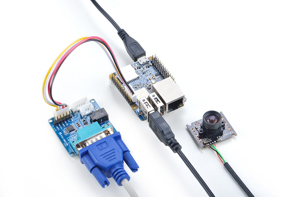
FA-CAM202是一款200万像素的USB摄像头模块,参考维基Matrix - USB_Camera(FA-CAM202)
启动系统,连接网络,以root用户登录终端并编译运行mjpg-streamer:
cd /root/mjpg-streamer
make
./start.sh
mjpg-streamer是一个开源的网络视频流服务器,在板子上成功运行mjpg-streamer后会打印下列信息:
 i: Using V4L2 device.: /dev/video0
 i: Desired Resolution: 1280 x 720
 i: Frames Per Second.: 30
 i: Format............: YUV
 i: JPEG Quality......: 90
 o: www-folder-path...: ./www/
 o: HTTP TCP port.....: 8080
 o: username:password.: disabled
 o: commands..........: enabled
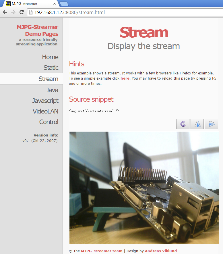
假设NEO Plus2的IP地址为192.168.1.123,在PC的浏览器中输入 192.168.1.123:8080 就能浏览摄像头采集的画面了,效果如下:
6.8 播放和录制音频
NEO Plus2只提供了音频硬件接口(2.0mm 5pin 排针),引脚的定义如下:
Pin# Name Description 1 MICIN1P Microphone Positive Input 2 MICIN1N Microphone Negative Input 3 LINEOUTR LINE-OUT Right Channel Output 4 GND 地 5 LINEOUTL LINE-OUT Left Channel Output
用户需自行转接音频设备,参考下图:
耳麦标注
只有在已外接音频设备的前提下,才可以进行下列步骤测试播放和录制音频。
查看系统里的声卡设备:
$ aplay -l
**** List of PLAYBACK Hardware Devices ****
card 0: audiocodec [audiocodec], device 0: SUNXI-CODEC sun50iw2codec-0 []
  Subdevices: 1/1
  Subdevice #0: subdevice #0
播放音频:
$ aplay /root/Music/test.wav -D plughw:0
录制音频:
$ arecord -f cd -d 5 test.wav
6.9 通过WiringNP测试GPIO
wiringPi库最早是由Gordon Henderson所编写并维护的一个用C语言写成的类库,除了GPIO库,还包括了I2C库、SPI库、UART库和软件PWM库等,由于wiringPi的API函数和arduino非常相似,这也使得它广受欢迎。
wiringPi库除了提供wiringPi类库及其头文件外,还提供了一个命令行工具gpio:可以用来设置和读写GPIO管脚,以方便在Shell脚本中控制GPIO管脚。
Ubuntu-Core系统中集成了这个工具以便客户测试GPIO管脚。详细信息请参看 WiringNP
7 如何编译Ubuntu-Core with Qt-Embedded系统
7.1 使用开源社区主线BSP
NEO Plus2现已支持使用64位Linux内核,并使用64位Ubuntu Core 16.04,关于H5芯片系列开发板使用主线U-boot和Linux-4.x.y的方法,请参考维基:Mainline U-boot & Linux
8 资源链接
8.1 手册原理图等开发资料
- Schematic: NanoPi-NEO-Plus2-1704-Schematic.pdf
- Dimensions: NanoPi-NEO-Plus2-1704_pcb的dxf文件
- H5 Datasheet: Allwinner_H5_Datasheet_V1.0.pdf
