Difference between revisions of "NanoPi NEO Core"
(→Introduction) |
(updated by API) |
||
| Line 147: | Line 147: | ||
===Install OS=== | ===Install OS=== | ||
====Get Image Files==== | ====Get Image Files==== | ||
| − | Visit this link [http:// | + | Visit this link [http://download.friendlyarm.com/nanopineocore download link] to download image files and the flashing utility:<br /> |
::{| class="wikitable" | ::{| class="wikitable" | ||
|- | |- | ||
Revision as of 09:27, 7 June 2018
Contents
- 1 Introduction
- 2 Hardware Spec
- 3 Diagram, Layout and Dimension
- 4 Get Started
- 5 Mini Shield for NanoPi NEO Core/Core2
- 6 FriendlyCore的使用
- 7 Make Your Own FriendlyCore
- 8 Connect External Modules to NEO Core
- 8.1 Connect Mini Shield for NanoPi NEO Core/Core2 to NEO Core
- 8.2 Connect Python Programmable NanoHat OLED to NEO Core
- 8.3 Connect Python Programmable NanoHat Motor to NEO Core
- 8.4 Connect NanoHat PCM5102A to NEO Core
- 8.5 Connect Arduino Compatible UNO Dock to NEO Core
- 8.6 Connect Power Dock to NEO Core
- 8.7 Connect NanoHat Proto to NEO Core
- 8.8 Connect Matrix - 2'8 SPI Key TFT to NanoPi NEO Core
- 9 3D Printing Files
- 10 Resources
- 11 Update Log
1 Introduction
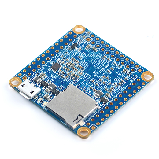
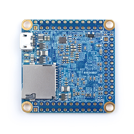
- The NanoPi NEO Core(abbreviated as "NEO Core") is an alternative NanoPi NEO that works like a CPU board with male pin-headers. It has the same form factor as the NanoPi NEO and same pin descriptions. The connectors and ports are populated to pin-headers on the NEO Core. The NanoPi NEO Core has ESD protection for its MicroUSB port and TF card slot. In addition the NEO Core can have an optional onboard eMMC flash which is preferred by industrial customers.
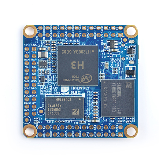
- The NEO Core uses a popular Allwinner H3 SoC and has onboard 256M/512M DDR3 RAM. FriendlyElec offers models with three eMMC options: 8GB/16GB/32GB and one that doesn't have eMMC at all.
- FriendlyElec migrated UbuntuCore with mainline kernel 4.x.y for it.
- FriendlyElec develops a Mini Shield for NanoPi NEO Core/Core2 which has the same form factor as the RPi 3. When a NanoPi NEO Core is connected to this Mini Shield the whole assembled module can be well fit into a common RPi 3's case.
2 Hardware Spec
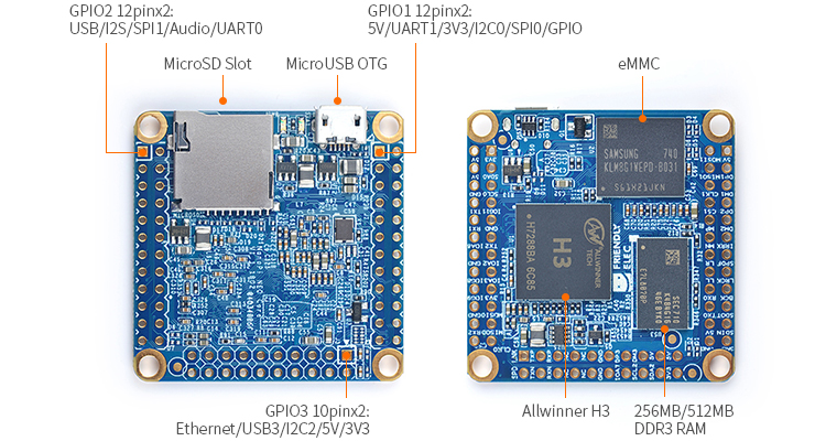
- CPU: Allwinner H3, Quad-core Cortex-A7 Up to 1.2GHz
- DDR3 RAM: 256MB/512MB DDR3 RAM
- Storage: NC/8GB/16GB/32GB eMMC
- MicroSD Slot x 1
- MicroUSB: OTG and power input
- GPIO: two 2.54mm spacing 12x2pin header,one 2.54mm spacing 10x2pin header
- Connectivity: 10/100M Ethernet(6Pin, included in 2.54mm pitch pin header)
- USB Host x3(included in 2.54mm pitch pin header)
- Debug Serial Port(4Pin, included in 2.54mm pitch pin header )
- Audio input/output Port(4Pin, included in 2.54mm pitch pin header )
- GPIO:It includes UART, SPI, I2C, IO etc
- PC Size: 40 x 40mm
- Power Supply: DC 5V/2A
- Temperature measuring range: -40℃ to 80℃
- OS/Software: U-boot,Ubuntu-Core
- Weight: xxg(WITHOUT Pin-headers)
3 Diagram, Layout and Dimension
3.1 Layout
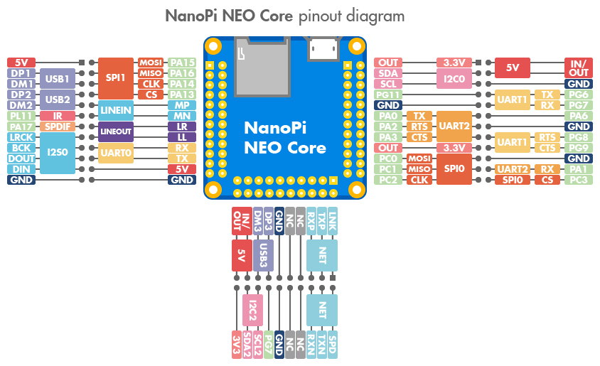
- GPIO1 Pin Description
Pin# Name Linux gpio Pin# Name Linux gpio 1 SYS_3.3V 2 VDD_5V 3 I2C0_SDA / GPIOA12 4 VDD_5V 5 I2C0_SCL / GPIOA11 6 GND 7 GPIOG11 203 8 UART1_TX / GPIOG6 198 9 GND 10 UART1_RX / GPIOG7 199 11 UART2_TX / GPIOA0 0 12 GPIOA6 6 13 UART2_RTS / GPIOA2 2 14 GND 15 UART2_CTS / GPIOA3 3 16 UART1_RTS / GPIOG8 200 17 SYS_3.3V 18 UART1_CTS / GPIOG9 201 19 SPI0_MOSI / GPIOC0 64 20 GND 21 SPI0_MISO / GPIOC1 65 22 UART2_RX / GPIOA1 1 23 SPI0_CLK / GPIOC2 66 24 SPI0_CS / GPIOC3 67
- GPIO2 Pin Description
Pin# Name Linux gpio Pin# Name Linux gpio 1 VDD_5V 2 SPI1_MOSI / GPIOA15 15 3 USB-DP1 4 SPI1_MISO / GPIOA16 16 5 USB-DM1 6 SPI1_CLK / GPIOA14 14 7 USB-DP2 8 SPI1_CS / GPIOA13 13 9 USB-DM2 10 MICIN1P 11 GPIOL11/IR-RX 363 12 MICIN1N 13 SPDIF-OUT/GPIOA17 17 14 LINEOUTR 15 PCM0_SYNC/I2S0_LRCK/I2C1_SCL 16 LINEOUTL 17 PCM0_CLK/I2S0_BCK/I2C1_SDA 18 UART_RXD0 / GPIOA5 / PWM0 5 19 PCM0_DOUT/I2S0_SDOUT 20 UART_TXD0 / GPIOA4 4 21 PCM0_DIN/I2S0_SDIN 22 VDD_5V 23 GND 24 GND
- GPIO3 Pin Description
Pin# Name Linux gpio Pin# Name Linux gpio 1 EPHY-LINK-LED 2 EPHY-SPD-LED 3 EPHY-TXP 4 EPHY-TXN 5 EPHY-RXP 6 EPHY-RXN 7 NC 8 NC 9 NC 10 NC 11 GND 12 GND 13 USB-DP3 14 GPIOA7 7 15 USB-DM3 16 I2C2_SCL / GPIOE12 17 5V 18 I2C2_SDA / GPIOE13 19 5V 20 SYS_3.3V
- Note:
- SYS_3.3V: 3.3V power output
- VVDD_5V: 5V power input/output. When the external device’s power is greater than the MicroUSB's the external device is charging the board otherwise the board powers the external device. The input range is 4.7V ~ 5.6V
- All pins are 3.3V, output current is 5mA
- For more details refer to its schematic
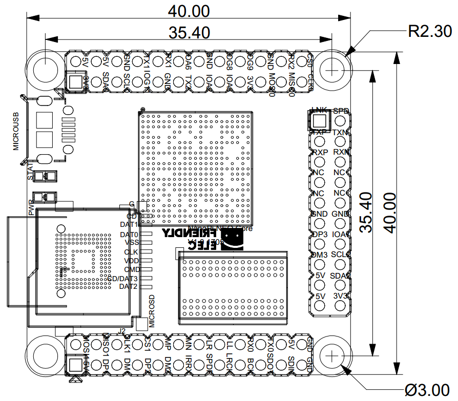
3.2 Dimensional Diagram
- For more details refer to the document: pcb in dxf format
- For more details refer to the document: pcb in dxf format
4 Get Started
4.1 Essentials You Need
Before starting to use your NanoPi NEO Core get the following items ready
- NanoPi NEO Core
- microSD Card/TF Card: Class 10 or Above, minimum 8GB SDHC
- microUSB power. A 5V/2A power is a must
- A Host computer running Ubuntu 16.04 64 bit system
4.2 TF Cards We Tested
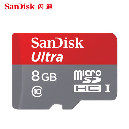
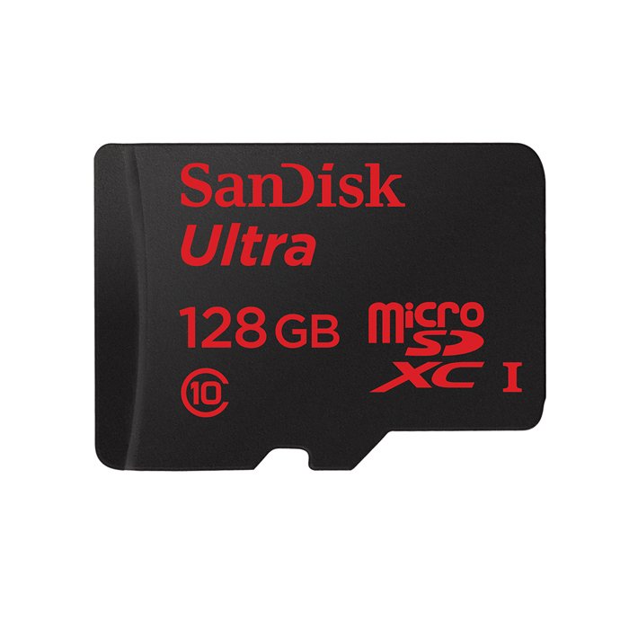
To make your NanoPi NEO Core boot and run fast we highly recommend you use a Class10 8GB SDHC TF card or a better one. The following cards are what we used in all our test cases presented here:
- SanDisk TF 8G Class10 Micro/SD TF card:
- SanDisk TF128G MicroSDXC TF 128G Class10 48MB/S:
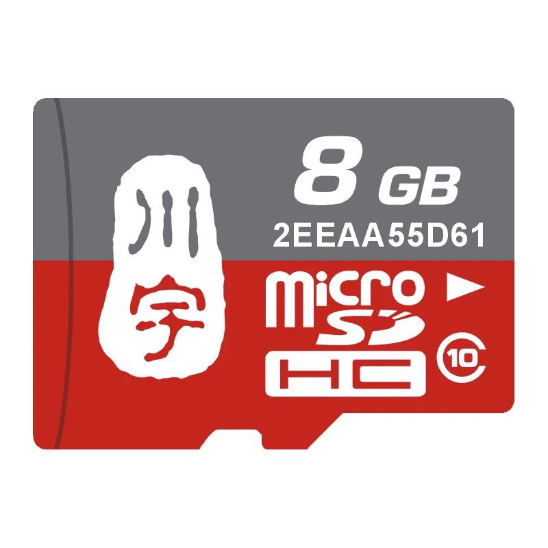
- 川宇 8G C10 High Speed class10 micro SD card:
4.3 Install OS
4.3.1 Get Image Files
Visit this link download link to download image files and the flashing utility:
Image Files: nanopi-neo-core_friendlycore-xenial_4.x.y_YYYYMMDD.img.zip FriendlyCore (base on UbuntuCore) Image File, kernel: Linux-4.x.y nanopi-neo-core_eflasher_4.x.y_YYYYMMDD.img.zip eflasher Image File, kernel: Linux-4.x.y nanopi-neo-core_ubuntu-oled_4.x.y_YYYYMMDD.img.zip Image File with Support for NanoHat OLED, kernel:Linux-4.x.y nanopi-neo-core_ubuntu-tft_4.x.y_YYYYMMDD.img.zip Image File with Support for Matrix - 2'8 SPI Key TFT, kernel:Linux-4.x.y Flash Utility: win32diskimager.rar Windows utility for flashing Debian image. Under Linux users can use "dd"
4.3.1.1 Flash to eMMC
4.3.1.1.1 Flash OS with eflasher Utility
- For more details about eflasher refer to the wiki link: EFlasher。
- Extract the eflasher Image and win32diskimager.rar files. Insert a TF card(at least 4G) into a Windows PC and run the win32diskimager utility as administrator. On the utility's main window select your TF card's drive, the wanted image file and click on "write" to start flashing the TF card.
- Insert this card into your board's BOOT slot and power on (with a 5V/2A power source). If the green LED is on and the blue LED is blinking this indicates your board has successfully booted.
- If your board doesn't support HDMI or no monitor is connected you can select an OS by running the following command:
$ su root
$ eflasher
The password for "root" is "fa".
We take "nanopi-neo-core_eflasher_friendlycore-xenial_4.14_armhf_YYYYMMDD.img" as an example. After you run the "eflasher" command you will see the following messages:
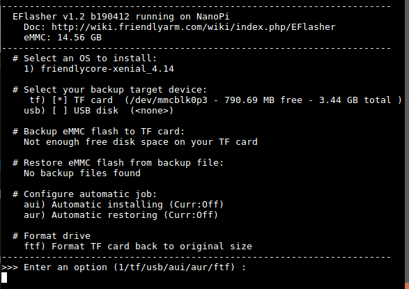
Type "1", select writing friendlycore system to eMMC you will see the following messages:
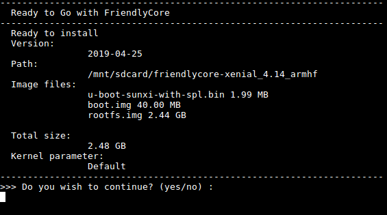
Type "yes" to start installation:

After it is done power off the system, take off the TF card, power on again your system will be booted from eMMC.
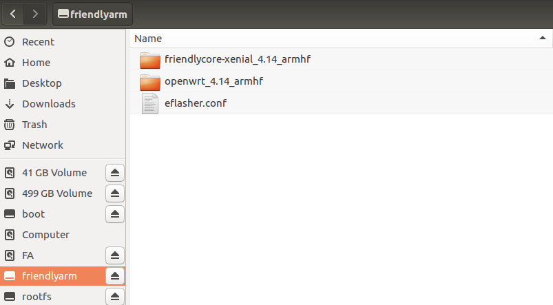
- If you want to flash other system to eMMC you can download the whole images-for-eflasher directory and extract the package under that directory to the FRIENDLYARM partition of an installation SD card.
5 Mini Shield for NanoPi NEO Core/Core2
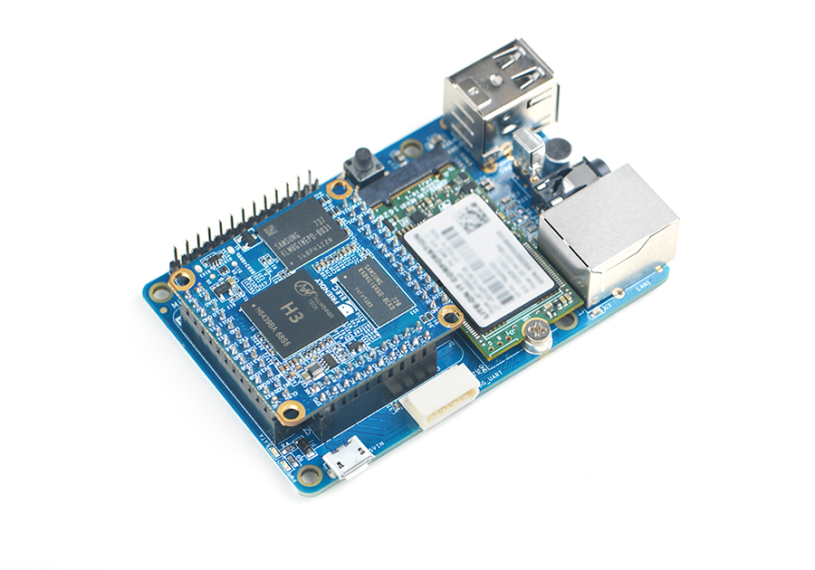
Here is a setup where we connect a NanoPi NEO Core to a Mini Shield for NanoPi NEO Core/Core2. Here is an introduction to Mini Shield for NanoPi NEO Core/Core2 Mini Shield
:
6 FriendlyCore的使用
6.1 介绍
FriendlyCore,是一个没有X-windows环境,基于Ubuntu core构建的系统,使用Qt-Embedded作为图形界面的轻量级系统,兼容Ubuntu系统软件源,非常适合于企业用户用作产品的基础OS。
本系统除了保留Ubuntu Core的特性以外,还包括以下特性:
- 集成Qt4.8;
- 集成NetworkManager网络管理器;
- 集成bluez等蓝牙相关软件包;
- 集成alsa相关软件包;
- 集成命令行系统配置工具npi-config;
- 集成Python GPIO模块RPiGPIO;
- 集成Python/C语言编写的demo程序,位于/root目录;
- 使能512M的swap分区;
6.2 运行FriendlyCore
- 对于有HDMI接口的板子,如果要在电视上进行操作,您需要连接USB鼠标和键盘。
- 如果您需要进行内核开发,最好选购一个串口配件,连接了串口,则可以通过串口终端对开发板进行操作。
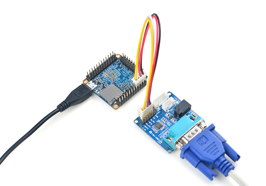
使用串口模块能有效地提升开发效率,以下是串口模块的连接方法:
接上串口后,您可以选择从串口模块的DC口或者从MicroUSB口 (如果有) 进行供电:
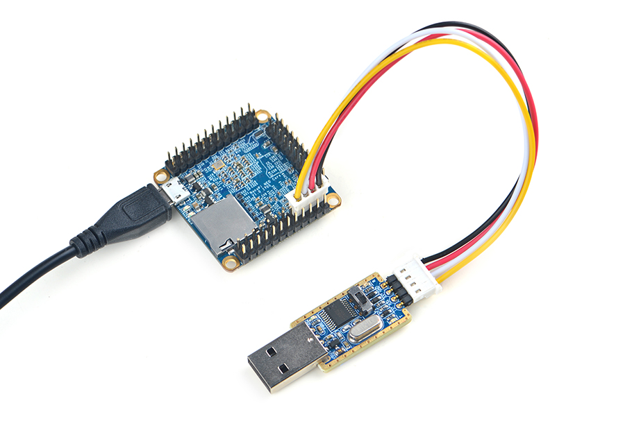
也可以使用USB转串口模块调试,请注意需要使用5V/2A电源给开发板MicroUSB供电:
- FriendlyCore默认帐户:
普通用户:
   用户名: pi
   密码: pi
Root用户:
   用户名: root
   密码: fa
默认会以 pi 用户自动登录,你可以使用 sudo npi-config 命令取消自动登录。
- 更新软件包:
$ sudo apt-get update
6.3 开发Qt应用
请参考 How to Build and Install Qt Application for FriendlyELEC Boards/zh
6.4 开机自动运行Qt示例程序
使用npi-config工具进行开启:
sudo npi-config进入Boot Options -> Autologin -> Qt/Embedded,选择Enable然后重启即可。
6.5 扩展TF卡文件系统
第一次启动FriendlyCore系统时,系统会自动扩展文件系统分区,请耐心等待,TF卡/eMMC的容量越大,需要等待的时间越长,进入系统后执行下列命令查看文件系统分区大小:
df -h
6.6 连接WiFi
无论是SD WiFi还是USB WiFi, 它们的连接方式都是一样的。正基科技的APXX系列芯片属于SD WiFi,另外系统默认也已经支持市面上众多常见的USB WiFi,已测试过的USB WiFi型号如下:
序号 型号 1 RTL8188CUS/8188EU 802.11n WLAN Adapter 2 RT2070 Wireless Adapter 3 RT2870/RT3070 Wireless Adapter 4 RTL8192CU Wireless Adapter 5 小米WiFi mt7601 6 5G USB WiFi RTL8821CU 7 5G USB WiFi RTL8812AU
目前使用 NetworkManager 工具来管理网络,其在命令行下对应的命令是 nmcli,要连接WiFi,相关的命令如下:
- 切换到root账户
$ su root
- 查看网络设备列表
$ nmcli dev注意,如果列出的设备状态是 unmanaged 的,说明网络设备不受NetworkManager管理,你需要清空 /etc/network/interfaces下的网络设置,然后重启.
- 开启WiFi
$ nmcli r wifi on- 扫描附近的 WiFi 热点
$ nmcli dev wifi- 连接到指定的 WiFi 热点
$ nmcli dev wifi connect "SSID" password "PASSWORD" ifname wlan0
请将 SSID和 PASSWORD 替换成实际的 WiFi名称和密码。
连接成功后,下次开机,WiFi 也会自动连接。
更详细的NetworkManager使用指南可参考这篇文章: Use NetworkManager to configure network settings
如果你的USB WiFi无法正常工作, 大概率是因为文件系统里缺少了对应的USB WiFi固件。对于Debian系统, 可以在Debian-WiFi里找到并安装USB WiFi芯片的固件。而对于Ubuntu系统, 则可以通过下列命令安装所有的USB WiFi固件:
$ apt-get install linux-firmware
一般情况下, 各种WiFi芯片的固件都存放在/lib/firmware目录下。
6.7 连接以太网
默认插上网线开机,会自动连接并通过DHCP获取IP地址,如需要配置静态IP地址,请参考 NetworkManager 的相关文档: Use NetworkManager to configure network settings。
6.8 访问GPIO/I2C/串口等硬件资源
请参考下面的文档:
- WiringNP: NanoPi NEO/NEO2/Air GPIO Programming with C/zh
- RPi.GPIO : NanoPi NEO/NEO2/Air GPIO Programming with Python/zh
6.9 定制命令行的欢迎信息(文字LOGO)
欢迎信息主要是这个目录下的脚本来打印的:
/etc/update-motd.d/
比如要修改 FriendlyELEC 的大字LOGO,可以修改/etc/update-motd.d/10-header 这个文件,比如要将LOGO改为HELLO,可将以下行:
TERM=linux toilet -f standard -F metal $BOARD_VENDOR
改为:
TERM=linux toilet -f standard -F metal HELLO
6.10 修改时区
例如更改为Shanghai时区:
sudo rm /etc/localtime
sudo ln -ls /usr/share/zoneinfo/Asia/Shanghai /etc/localtime
6.11 选择系统默认音频设备
如果当前系统存在多个音频设备, 例如HDMI-Audio、3.5mm耳机座、I2S-Codec时, 可以通过下列操作设置系统默认使用的音频设备。
- 启动板子后,执行以下步骤安装alsa包:
$ apt-get update
$ apt-get install libasound2
$ apt-get install alsa-base
$ apt-get install alsa-utils
- 安装好需要的库后,查看系统当前所有的声卡设备的序列号。这里假设aplay的输出如下, 并不是真实情况, 请根据实际情况进行相对应的修改:
$ aplay -l
card 0: HDMI
card 1: 3.5mm codec
card 2: I2S codec
上面的信息表示card 0代表HDMI-Audio,card 1代表3.5mm耳机座, card 2代表I2S-Codec,修改配置文件/etc/asound.conf如下表示选择HDMI-Audio:
pcm.!default {
    type hw
    card 0
    device 0
}

ctl.!default {
    type hw
    card 0
}
如果将card 0修改为card 1, 则表示选择3.5mm耳机座, 以此类推。
拷贝一首 .wav 格式的音乐到开发板上,播放音乐:
$ aplay /root/Music/test.wav
可以听见从系统默认的音频设备里输出音频。
如果您使用的开发板是H3/H5/H2+系列并且使用的是主线内核,那么更简便的方法是使用npi-config。
6.12 连接USB摄像头模块(FA-CAM202)
FA-CAM202是一款200万像素的USB摄像头模块,连接开发板和摄像头,然后上电启动系统,连接网络,以root用户登录终端并编译运行mjpg-streamer:
$ cd /root/C/mjpg-streamer
$ make
$ ./start.sh
请自行修改start.sh, 确保使用正确的/dev/videoX节点, 下列命令可以用来确定摄像头的video节点:
$ apt-get install v4l-utils
$ v4l2-ctl -d /dev/video0 -D
# fa-cam202有2个型号
Driver Info (not using libv4l2):
        Driver name   : uvcvideo
        Card type     : HC 3358+2100: HC 3358+2100  / USB 2.0 Camera: USB 2.0 Camera
        Bus info      : usb-1c1b000.usb-1
	...
上述信息表示/dev/video0是摄像头的设备节点。mjpg-streamer是一个开源的网络视频流服务器,在板子上成功运行mjpg-streamer后会打印下列信息:
$ ./start.sh
 i: Using V4L2 device.: /dev/video0
 i: Desired Resolution: 1280 x 720
 i: Frames Per Second.: 30
 i: Format............: YUV
 i: JPEG Quality......: 90
 o: www-folder-path...: ./www/
 o: HTTP TCP port.....: 8080
 o: username:password.: disabled
 o: commands..........: enabled
start.sh脚本里执行了下列2个命令:
export LD_LIBRARY_PATH="$(pwd)"
./mjpg_streamer -i "./input_uvc.so -d /dev/video0 -y 1 -r 1280x720 -f 30 -q 90 -n -fb 0" -o "./output_http.so -w ./www"
mjpg_streamer相关参数的含义如下:
-i: 选择输入插件,input_uvc.so表示从摄像头采集数据;
-o: 选择输出插件,output_http.so表示使用http协议传输数据;
-d: 输入插件的子参数,指定摄像头设备节点;
-y: 输入插件的子参数,指定摄像头采集数据的格式,1:yuyv, 2:yvyu, 3:uyvy 4:vyuy,如果不使用-y参数,则表示采集MJPEG格式;
-r: 输入插件的子参数,指定摄像头采集分辨率;
-f: 输入插件的子参数,指定想使用的摄像头采集fps,具体是否支持依赖于驱动;
-q: 输入插件的子参数,指定libjpeg软编码的图像质量;
-n: 输入插件的子参数, 禁止dynctrls功能;
-fb: 输入插件的子参数, 指定是否在/dev/fbX上显示采集的图像;
-w: 输出插件的子参数, 指定包含网页的目录;
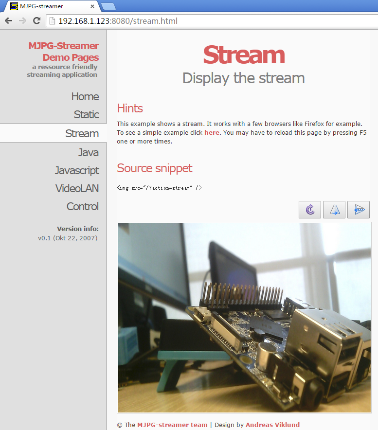
成功运行start.sh脚本后,假设开发板的IP地址为192.168.1.230,在PC的浏览器中输入 192.168.1.230:8080 就能浏览摄像头采集的画面了,效果如下:
6.13 查看CPU温度和频率
命令行查看:
$ cpu_freq
Aavailable frequency(KHz):
        480000 624000 816000 1008000
Current frequency(KHz):
        CPU0 online=1 temp=26548C governor=ondemand freq=624000KHz
        CPU1 online=1 temp=26548C governor=ondemand freq=624000KHz
        CPU2 online=1 temp=26548C governor=ondemand freq=624000KHz
        CPU3 online=1 temp=26548C governor=ondemand freq=624000KHz
上述信息表示当前有4个CPU核在线, 温度均约为26.5摄氏度, 运行的策略均为根据需求来决定运行频率, 当前的运行频率均为624MHz,设置频率的命令如下:
$ cpu_freq -s 1008000
Aavailable frequency(KHz):
        480000 624000 816000 1008000
Current frequency(KHz):
        CPU0 online=1 temp=36702C governor=userspace freq=1008000KHz
        CPU1 online=1 temp=36702C governor=userspace freq=1008000KHz
        CPU2 online=1 temp=36702C governor=userspace freq=1008000KHz
        CPU3 online=1 temp=36702C governor=userspace freq=1008000KHz
上述命令将4个CPU核的频率设置为1008MHz。
6.14 运行Qt示例程序
执行以下命令:
$ sudo /opt/QtE-Demo/run.sh
运行结果如下,这是一个开源的QtDemo:
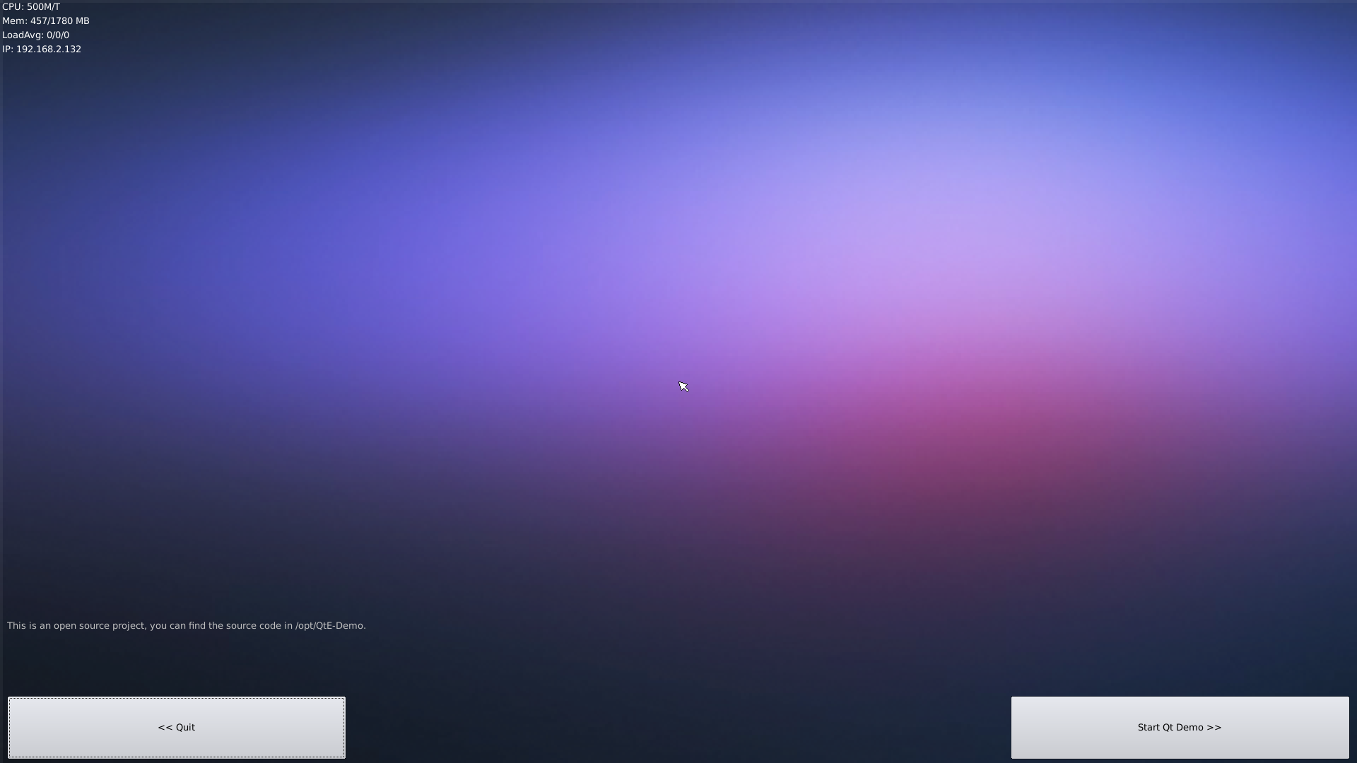
6.15 Docker在armhf系统下的安装与使用
6.15.1 安装 Docker
执行下列命令:
sudo apt-get update
sudo apt-get install docker.io
6.15.2 测试 Docker
执行下列命令运行一个简单的docker image:
git clone https://github.com/friendlyarm/debian-jessie-arm-docker
cd debian-jessie-arm-docker
./rebuild-image.sh
./run.sh
7 Make Your Own FriendlyCore
7.1 Use Mainline BSP
The NanoPi NEO Core has gotten support for kernel Linux-4.x.y with Ubuntu Core 16.04. For more details about how to use mainline u-boot and Linux-4.x.y refer to :Mainline U-boot & Linux
8 Connect External Modules to NEO Core
8.1 Connect Mini Shield for NanoPi NEO Core/Core2 to NEO Core
8.2 Connect Python Programmable NanoHat OLED to NEO Core
The NanoHat OLED module is a small and cute monochrome OLED module with low power consumption. It has three user buttons. We provide its driver's source code and a user friendly shell interface on which you can check system information and status.A customized aluminum case is made for it. You cannot miss this lovely utility! Here is a hardware setup:NanoHat OLED
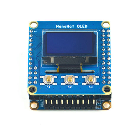
8.3 Connect Python Programmable NanoHat Motor to NEO Core
The NanoHat Motor module can drive four 5V PWM steering motors and four 12V DC motors or four 5V PWM steering motors and two 12V four-wire step motors.Here is a hardware setup: NanoHat Motor
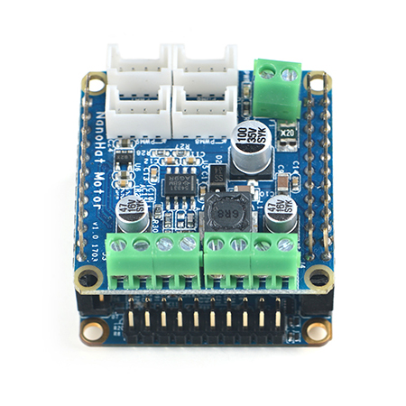
8.4 Connect NanoHat PCM5102A to NEO Core
The NanoHat PCM5102A module uses TI's DAC audio chip PCM5102A, a convenient and easy-to-use audio module for hobbyists. Here is a hardware setup:NanoHat PCM5102A
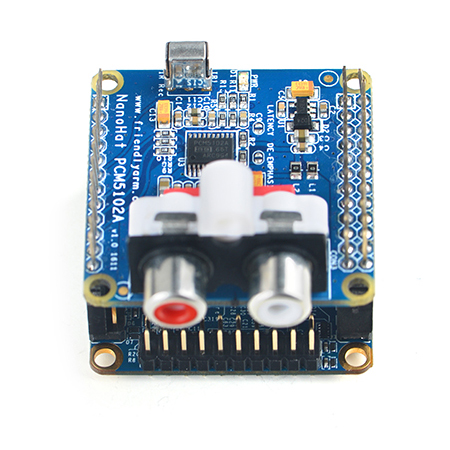
8.5 Connect Arduino Compatible UNO Dock to NEO Core
The UNO Dock module is an Arduino board compatible with Arduino UNO and works with Arduino programs.You can use Arduino IDE to run all Arduino programs on the Dock.It also exposes the NanoPi NEO Core's pins.It converts 12V power input to 5V/2A output.You can search for various code samples from Ubuntu's ecosystem and run on the Dock. These features make it a powerful platform for IOT projects and cloud related applications. Here is a hardware setup:UNO Dock for NanoPi NEO v1.0
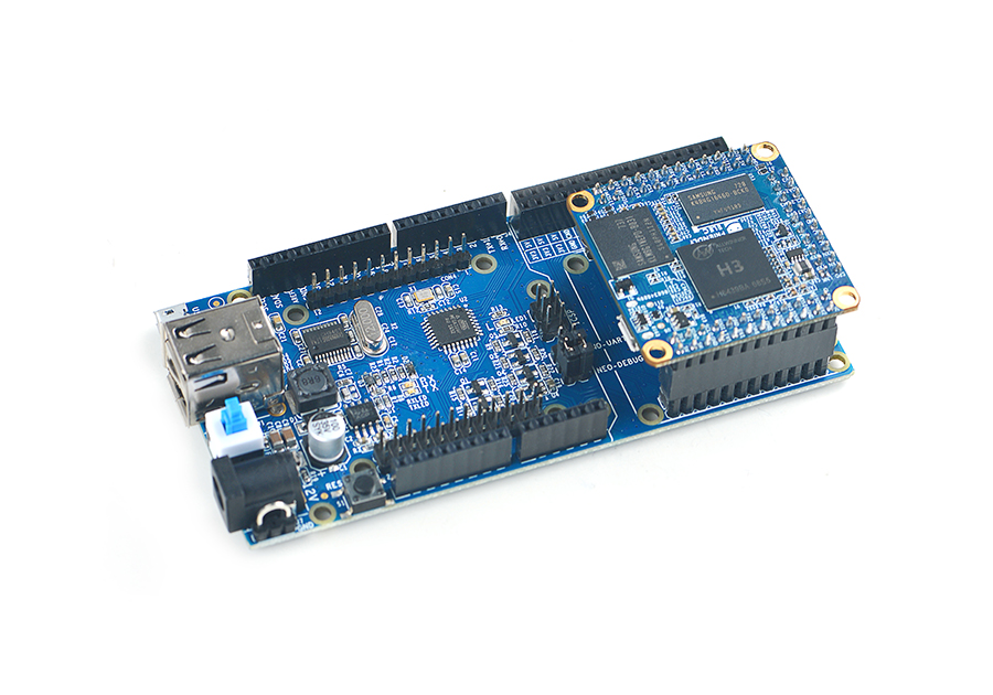
8.6 Connect Power Dock to NEO Core
The Power Dock for NanoPi NEO Core is a high efficiency power conversion module. It provides stable and reliable power source. Here is a hardware setup:Power Dock for NanoPi NEO
Power Dock for NanoPi NEO_nanopi_NEO_Core
8.7 Connect NanoHat Proto to NEO Core
The NanoHat Proto is an expansion board which exposes NEO Core's various pins.It has an onboard EEPROM for data storage.Here is a hardware setup:NanoHat Proto
Matrix - NanoHat Proto_nanopi_NEO_Core
8.8 Connect Matrix - 2'8 SPI Key TFT to NanoPi NEO Core
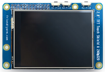
The Matrix-2'8_SPI_Key_TFT module is a 2.8" TFT LCD with resistive touch. It uses the ST7789S IC and XPT2046 resistive touch IC. It has SPI interface and three configurable user keys.Here is its wiki page Matrix - 2'8 SPI Key TFT
9 3D Printing Files
10 Resources
10.1 Datasheet & Schematics
- Schematic NanoPi-NEO-Core-V1.1-1802-Schematic.pdf
- Schematic NanoPi-NEO-Core-V1.0-1705-Schematic.pdf
- Dimensional Diagram NanoPi-NEO-Core-1705 pcb的dxf文件
- H3's datasheet Allwinner_H3_Datasheet_V1.2.pdf
11 Update Log
11.1 Dec-1-2017
- Released English version
