Difference between revisions of "Matrix - Water Sensor"
(→代码说明) |
(→Basic Device Operation) |
||
| (5 intermediate revisions by the same user not shown) | |||
| Line 1: | Line 1: | ||
[[Matrix - Water Sensor/zh|查看中文]] | [[Matrix - Water Sensor/zh|查看中文]] | ||
| − | == | + | ==Introduction== |
| − | [[File:Water Sensor.jpg|thumb| | + | [[File:Water Sensor.jpg|thumb|Water Sensor]] |
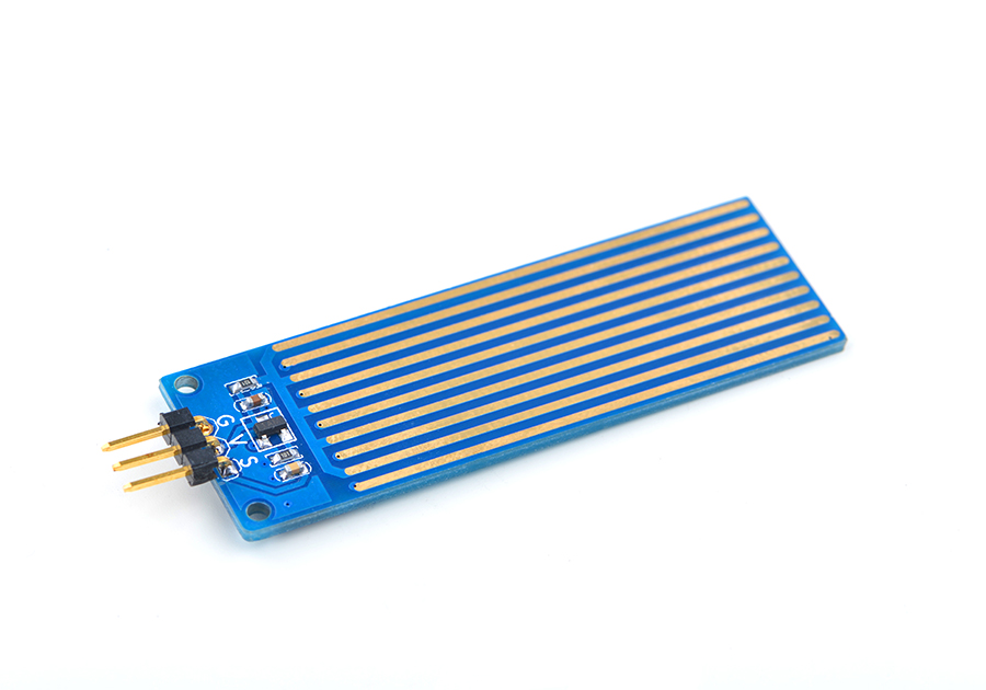
| − | * | + | * The Matrix-Water_Sensor is a simple sensor module. It can be used to detect a water level and convert the amount of water to analog signals. |
| − | * | + | * Its sensitivity can be adjusted via a potentiometer. |
| − | == | + | ==Features== |
| − | * | + | * Standard 3 Pin interface |
| − | * | + | * PCB dimension(mm): 16 x 60 |
| − | + | ||
[[File:Soil_Moisture_Sensor.png | frameless|350px|Water Sensor.PCB]] | [[File:Soil_Moisture_Sensor.png | frameless|350px|Water Sensor.PCB]] | ||
| Line 24: | Line 23: | ||
|} | |} | ||
| − | == | + | ==Basic Device Operation== |
| − | * | + | * The module has a series of exposed traces. The resistance of these exposed traces are proportional to the water level. This mechanism is used to measure the amount of water and therefore calculate the water level. It can be used to detect whether or not there is rainfall as well. |
| − | + | ||
==Applications== | ==Applications== | ||
| Line 152: | Line 150: | ||
For more details about this APIs called in this code sample refer to [[Matrix API reference manual]] <br> | For more details about this APIs called in this code sample refer to [[Matrix API reference manual]] <br> | ||
| − | == | + | ==Resources== |
| + | |||
| + | ==Update Log== | ||
| + | ===June-28-2016=== | ||
| + | * Created English wiki | ||
Latest revision as of 02:33, 8 August 2016
Contents
1 Introduction
- The Matrix-Water_Sensor is a simple sensor module. It can be used to detect a water level and convert the amount of water to analog signals.
- Its sensitivity can be adjusted via a potentiometer.
2 Features
- Standard 3 Pin interface
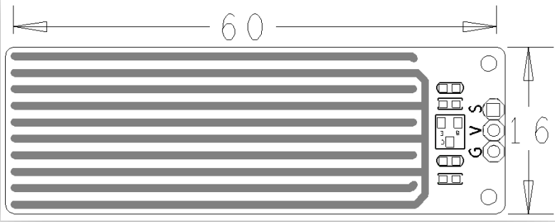
- PCB dimension(mm): 16 x 60
- Pin Description
| Pin | Description |
| S | GPIO |
| V | Supply Voltage 5V |
| G | Ground |
3 Basic Device Operation
- The module has a series of exposed traces. The resistance of these exposed traces are proportional to the water level. This mechanism is used to measure the amount of water and therefore calculate the water level. It can be used to detect whether or not there is rainfall as well.
4 Applications
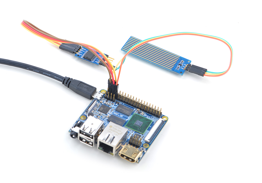
The Matrix-Water_Sensor module outputs analog signals which can be converted to digital signals through an ADC converter e.g. the Matrix-Analog_to_Digital_Converter module.
For more details about the Matrix-Analog_to_Digital_Converter module refer to wiki:Matrix_-_Analog_to_Digital_Converter。
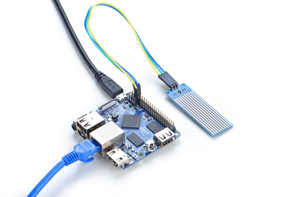
4.1 Connect to NanoPi M1
Refer to the following connection diagram to connect the module to the NanoPi M1:

Connection Details:
| Matrix-Water_Sensor | |
| GND | NanoPi M1 Pin9 |
| 5V | NanoPi M1 Pin2 |
| S | Matrix-Analog_to_Digital_Converter A0 |
4.2 Connect to NanoPi 2
Refer to the following connection diagram to connect the module to the NanoPi 2:
Matrix-Water_Sensor_nanopi_2
Connection Details:
| Matrix-Water_Sensor | |
| GND | NanoPi 2 Pin9 |
| 5V | NanoPi 2 Pin2 |
| S | Matrix-Analog_to_Digital_Converter A0 |
4.3 Connect to NanoPi M2 / NanoPi 2 Fire
Refer to the following connection diagram to connect the module to the NanoPi M2/ NanoPi 2 Fire:

Connection Details:
| Matrix-Water_Sensor | |
| GND | NanoPi M2 Pin9 |
| 5V | NanoPi M2 Pin2 |
| S | Matrix-Analog_to_Digital_Converter A0 |
4.4 Connect to NanoPC-T2
Refer to the following connection diagram to connect the module to the NanoPC-T2:
Matrix-Water_Sensor_NanoPC-T2
Connection Details:
| Matrix-Potentiometer | |
| GND | NanoPC-T2 USB Host GND |
| 5V | NanoPC-T2 USB Host 5V |
| S | Matrix-Analog_to_Digital_Converter A0 |
5 Compile & Run Test Program
Boot your ARM board with Debian and copy the matrix code:
$ apt-get update && apt-get install git
$ git clone https://github.com/friendlyarm/matrix.git
If your cloning is done successfully a "matrix" directory will be generated.
Compile and install Matrix:
$ cd matrix
$ make && make install
Run test program:
$ matrix-adcNote: this module is not plug and play therefore before running the module please make sure it is connected to an ARM board.
Here is what you should observe:
The channel0 value is 24606 Code Sample
This Matrix code sample can work with all the ARM boards mentioned in this module's wiki. The name of this code sample is "matrix-analog_to_digital_converter". Here is its source code:
int main(int argc, char ** argv)
{
    int i = 0;
    int value = 0;
    int channel = 0;

    if (boardInit() < 0) {
        printf("Fail to init board\n");
        return -1;
    }

    if (argc == 2)
        channel = atoi(argv[1]);
    system("modprobe "DRIVER_MODULE);
    signal(SIGINT, intHandler);
    for (i=0; i<ADC_READ_TIMES; i++) {
        if (pcf8591Read(channel, &value) != -1) {
            printf("The channel%d value is %d\n", channel, value);
        } else {
            printf("Fail to get channel%d value\n", channel);
        }
    }
    system("rmmod "DRIVER_MODULE);

    return 0;
}
For more details about this APIs called in this code sample refer to Matrix API reference manual
7 Resources
8 Update Log
8.1 June-28-2016
- Created English wiki

