Difference between revisions of "Matrix - Photoresistor"
(→介绍) |
(→Compile & Run Test Program) |
||
| (24 intermediate revisions by 4 users not shown) | |||
| Line 1: | Line 1: | ||
| − | [[Matrix - Photoresistor| | + | [[Matrix - Photoresistor/zh|查看中文]] |
| − | == | + | ==Introduction== |
| − | [[File: | + | [[File:Photoresistor.png|thumb|Photoresistor]] |
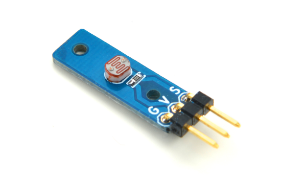
| − | + | *The Matrix-Photoresistor is a photoresistor module. It has a 3 pin 2.54mm spacing pin-header of which V is supply voltage, G is ground and s is output analog signal. The output signal decreases with increasing incident light intensity. Users can convert its output analog signal to a digital signal via ADC conversion. | |
| − | + | *Output Voltage: 0 ~ Vcc | |
| − | *Matrix- | + | |
| − | * | + | |
| − | == | + | ==Features== |
| − | * | + | * GPIO 3.3/5V |
| − | * | + | * Small |
| − | * 2. | + | * 2.54mm spacing pin-header |
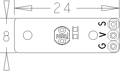
| − | * | + | * PCB Dimension(mm): 8 x 24 |
[[File:xxx.png | frameless|400px|Photoresistor.PCB]] | [[File:xxx.png | frameless|400px|Photoresistor.PCB]] | ||
| − | * | + | * Pin Description: |
{| class="wikitable" | {| class="wikitable" | ||
|- | |- | ||
| − | | | + | |Pin || Description |
|- | |- | ||
| − | |S || GPIO | + | |S || Analog GPIO |
|- | |- | ||
| − | |V || | + | |V || Supply Voltage 5V |
|- | |- | ||
| − | |G || | + | |G || Ground |
|} | |} | ||
| − | == | + | ==Basic Device Operation== |
| − | * | + | *The module has a photoresistor. The resistance of a photoresistor decreases with increasing incident light intensity; in other words, it exhibits photoconductivity.If incident light on a photoresistor exceeds a certain frequency, photons absorbed by the semiconductor give bound electrons enough energy to jump into the conduction band. The resulting free electrons (and their hole partners) conduct electricity, thereby lowering resistance. |
| − | == | + | ==Applications== |
| + | The Matrix-Photoresistor module outputs analog signals which can be converted to digital signals through an ADC converter e.g. the Matrix-Analog_to_Digital_Converter module.<br> | ||
| + | For more details about the Matrix-Analog_to_Digital_Converter module refer to wiki: [[Matrix_-_Analog_to_Digital_Converter]].<br> | ||
| + | |||
| + | ===Connect to NanoPi M1=== | ||
| + | Refer to the following connection diagram to connect the module to the NanoPi M1:<br> | ||
| + | [[File:Matrix-Photoresistor_nanopi_m1.jpg|frameless|600px|Matrix-Photoresistor_nanopi_m1]] | ||
| + | |||
| + | Connection Details: | ||
| + | {| class="wikitable" | ||
| + | |- | ||
| + | |Matrix-Photoresistor || | ||
| + | |- | ||
| + | |GND || NanoPi M1 Pin9 | ||
| + | |- | ||
| + | |5V || NanoPi M1 Pin2 | ||
| + | |- | ||
| + | |S || Matrix-Analog_to_Digital_Converter A0 | ||
| + | |} | ||
| + | |||
| + | ===Connect to NanoPi 2=== | ||
| + | Refer to the following connection diagram to connect the module to the NanoPi 2:<br> | ||
| + | [[File:Matrix-Photoresistor_nanopi_2.jpg|frameless|600px|Matrix-Photoresistor_nanopi_2]] | ||
| + | |||
| + | Connection Details: | ||
| + | {| class="wikitable" | ||
| + | |- | ||
| + | |Matrix-Photoresistor || | ||
| + | |- | ||
| + | |GND || NanoPi 2 Pin9 | ||
| + | |- | ||
| + | |5V || NanoPi 2 Pin2 | ||
| + | |- | ||
| + | |S || Matrix-Analog_to_Digital_Converter A0 | ||
| + | |} | ||
| + | |||
| + | ===Connect to NanoPi M2 / NanoPi 2 Fire=== | ||
| + | Refer to the following connection diagram to connect the module to the NanoPi M2/ NanoPi 2 Fire.<br> | ||
| + | [[File:Matrix-Photoresistor_nanopi_m2.jpg|frameless|600px|Matrix-Photoresistor_nanopi_m2]] | ||
| + | |||
| + | Connection Details: | ||
| + | {| class="wikitable" | ||
| + | |- | ||
| + | |Matrix-Photoresistor || | ||
| + | |- | ||
| + | |GND || NanoPi M2 Pin9 | ||
| + | |- | ||
| + | |5V || NanoPi M2 Pin2 | ||
| + | |- | ||
| + | |S || Matrix-Analog_to_Digital_Converter A0 | ||
| + | |} | ||
| + | |||
| + | ===Connect to NanoPC-T2=== | ||
| + | Refer to the following connection diagram to connect the module to the NanoPC-T2:<br> | ||
| + | [[File:Matrix-Photoresistor_NanoPC-T2.jpg|frameless|600px|Matrix-Photoresistor_NanoPC-T2]] | ||
| + | |||
| + | Connection Details: | ||
| + | {| class="wikitable" | ||
| + | |- | ||
| + | |Matrix-Potentiometer || | ||
| + | |- | ||
| + | |GND || NanoPC-T2 USB Host GND | ||
| + | |- | ||
| + | |5V || NanoPC-T2 USB Host 5V | ||
| + | |- | ||
| + | |S || Matrix-Analog_to_Digital_Converter A0 | ||
| + | |} | ||
| + | |||
| + | ==Compile & Run Test Program== | ||
| + | Boot your ARM board with Debian and copy the matrix code: | ||
| + | <syntaxhighlight lang="bash"> | ||
| + | $ apt-get update && apt-get install git | ||
| + | $ git clone https://github.com/friendlyarm/matrix.git | ||
| + | </syntaxhighlight> | ||
| + | If your cloning is done successfully a "matrix" directory will be generated. | ||
| + | |||
| + | Compile and install Matrix: | ||
| + | <syntaxhighlight lang="bash"> | ||
| + | $ cd matrix | ||
| + | $ make && make install | ||
| + | </syntaxhighlight> | ||
| + | |||
| + | Run test program: | ||
| + | <syntaxhighlight lang="bash"> | ||
| + | $ matrix-adc | ||
| + | </syntaxhighlight> | ||
| + | Note: this module is not plug and play therefore before running the module please make sure it is connected to an ARM board.<br> | ||
| + | Here is what you should observe:<br> | ||
| + | <syntaxhighlight lang="bash"> | ||
| + | The channel0 value is 2460 | ||
| + | </syntaxhighlight> | ||
| + | The resistance of a photoresistor decreases with increasing incident light intensity. | ||
| + | |||
| + | ==Code Sample== | ||
| + | This Matrix code sample can work with all the ARM boards mentioned in this module's wiki. The name of this code sample is "matrix-3_axis_digital_compass". Here is its source code: | ||
| + | <syntaxhighlight lang="c"> | ||
| + | int main(int argc, char ** argv) | ||
| + | { | ||
| + | int i = 0; | ||
| + | int value = 0; | ||
| + | int channel = 0; | ||
| + | |||
| + | if (boardInit() < 0) { | ||
| + | printf("Fail to init board\n"); | ||
| + | return -1; | ||
| + | } | ||
| + | |||
| + | if (argc == 2) | ||
| + | channel = atoi(argv[1]); | ||
| + | system("modprobe "DRIVER_MODULE); | ||
| + | signal(SIGINT, intHandler); | ||
| + | for (i=0; i<ADC_READ_TIMES; i++) { | ||
| + | if (pcf8591Read(channel, &value) != -1) { | ||
| + | printf("The channel%d value is %d\n", channel, value); | ||
| + | } else { | ||
| + | printf("Fail to get channel%d value\n", channel); | ||
| + | } | ||
| + | } | ||
| + | system("rmmod "DRIVER_MODULE); | ||
| + | |||
| + | return 0; | ||
| + | } | ||
| + | </syntaxhighlight> | ||
| + | For more details about this APIs called in this code sample refer to [[Matrix API reference manual]] <br> | ||
| + | |||
| + | ==Resources== | ||
| + | |||
| + | ==Update Log== | ||
| + | ===June-22-2016=== | ||
| + | * Created English wiki | ||
| + | |||
| + | <!--- | ||
| + | ==Download Matrix Source Code== | ||
| + | All the matrix modules' code samples are open source. They are maintained on GitHub: https://github.com/friendlyarm/matrix.git <br> | ||
| + | Each branch in this hub contains the matrix modules' code samples for a board that the matrix modules can work with.<br> | ||
| + | * The nanopi branch contains the matrix modules' code samples for the NanoPi | ||
| + | * The nanopi2 branch contains the matrix modules' code samples for the NanoPi 2 | ||
| + | * the tiny4412 branch contains the matrix modules' code samples for the Tiny4412 | ||
| + | * the raspberrypi branch contains the matrix modules' code samples for the RaspberryPi | ||
| + | |||
| + | Please follow the steps below to get the source code<br> | ||
| + | Install the git utility on a PC running Ubuntu14.04 | ||
| + | <syntaxhighlight lang="bash"> | ||
| + | $ sudo apt-get install git | ||
| + | </syntaxhighlight> | ||
| + | |||
| + | Clone the matrix code from GitHub | ||
| + | <syntaxhighlight lang="bash"> | ||
| + | $ git clone https://github.com/friendlyarm/matrix.git | ||
| + | </syntaxhighlight> | ||
| + | If this is successful a "matrix" directory will be generated, which will contain all the matrix modules' code samples. | ||
| + | |||
| + | ==Connect to NanoPi 2== | ||
| + | ===Hardware Connection=== | ||
| + | Please refer to the following connection diagram to connect the Matrix-Photoresistor to the NanoPi 2:<br> | ||
| + | [[File:Matrix-Photoresistor_nanopi_2.jpg|frameless|600px|Matrix-Photoresistor_nanopi_2]] | ||
| + | |||
| + | Connection Details: | ||
| + | {| class="wikitable" | ||
| + | |- | ||
| + | |Matrix-Analog_to_Digital_Converter || NanoPi 2 | ||
| + | |- | ||
| + | |SDA || Pin3 | ||
| + | |- | ||
| + | |SCL || Pin5 | ||
| + | |- | ||
| + | |5V || Pin4 | ||
| + | |- | ||
| + | |GND || Pin6 | ||
| + | |} | ||
| + | |||
| + | {| class="wikitable" | ||
| + | |- | ||
| + | |Matrix-Photoresistor || | ||
| + | |- | ||
| + | |GND || NanoPi 2 Pin9 | ||
| + | |- | ||
| + | |5V || NanoPi 2 Pin2 | ||
| + | |- | ||
| + | |S || Matrix-Analog_to_Digital_Converter A0 | ||
| + | |} | ||
| + | This module's output signals are analog signals. You can use our Matrix-Analog_to_Digital_Converter to convert them to digital signals.<br> | ||
| + | Please connect the Matrix-Analog_to_Digital_Converter to the NanoPi 2 and then connect Pin S of the Matrix-Photoresistor's pin header to Matrix-Analog_to_Digital_Converter's A0.<br> | ||
| + | For more details about the Matrix-Analog_to_Digital_Converter module please refer to wiki:[[Matrix_-_Analog_to_Digital_Converter]].<br> | ||
| + | |||
| + | ===Compile Test Program=== | ||
| + | Please login the matrix hub and enter the nanopi2 branch | ||
| + | <syntaxhighlight lang="bash"> | ||
| + | $ cd matrix | ||
| + | $ git checkout nanopi2 | ||
| + | </syntaxhighlight> | ||
| + | |||
| + | Compile the Matrix code | ||
| + | <syntaxhighlight lang="bash"> | ||
| + | $ make CROSS_COMPILE=arm-linux- clean | ||
| + | $ make CROSS_COMPILE=arm-linux- | ||
| + | $ make CROSS_COMPILE=arm-linux- install | ||
| + | </syntaxhighlight> | ||
| + | Note: please make sure to install the cross compiler "arm-linux-gcc-4.9.3" on your PC, which is used to compile files for the NanoPi 2.<br> | ||
| + | Generated library files are under the "install/lib" directory. The test program is under the "install/usr/bin" directory. Its test program is "matrix-adc"<br> | ||
| + | The modules are under the "modules" directory. Its driver's source code is in https://github.com/friendlyarm/linux-3.4.y.git <br> | ||
| + | |||
| + | ===Run Test Program=== | ||
| + | Please insert a TF card which is flashed with Debian to a Linux host and mount its boot and rootfs sections.<br> | ||
| + | We assume the rootfs is mounted to /media/rootfs then please run the following commands to copy the driver, library and test program to the card.<br> | ||
| + | <syntaxhighlight lang="bash"> | ||
| + | $ cp modules /media/rootfs/ -r | ||
| + | $ cp install/lib/* /media/rootfs/lib/ -d | ||
| + | $ cp install/usr/bin/* /media/rootfs/usr/bin/ | ||
| + | </syntaxhighlight> | ||
| + | |||
| + | Insert this TF card to your NanoPi 2, power on and run the following commands to load the driver.<br> | ||
| + | <syntaxhighlight lang="bash"> | ||
| + | $ cd /modules | ||
| + | $ insmod pcf8591.ko | ||
| + | </syntaxhighlight> | ||
| + | |||
| + | Please run the following command to test the Matrix-Photoresistor module.<br> | ||
| + | <syntaxhighlight lang="bash"> | ||
| + | $ matrix-adc | ||
| + | </syntaxhighlight> | ||
| + | Here is what you should expect:<br> | ||
| + | [[File:matrix-adc_result.png|frameless||matrix-adc_result]] <br> | ||
| + | |||
| + | ===Code Sample=== | ||
| + | <syntaxhighlight lang="c"> | ||
| + | int main(int argc, char ** argv) | ||
| + | { | ||
| + | int i = 0; | ||
| + | int value = 0; | ||
| + | int channel = 0; | ||
| + | |||
| + | if (argc == 2) { | ||
| + | channel = atoi(argv[1]); | ||
| + | } | ||
| + | |||
| + | for (i=0; i<ADC_READ_TIMES; i++) { | ||
| + | if (pcf8591Read(channel, &value) != -1) { | ||
| + | printf("channel%d value=%d\n", channel, value); | ||
| + | } else { | ||
| + | printf("Fail to get channel%d value\n", channel); | ||
| + | } | ||
| + | usleep(10000); | ||
| + | } | ||
| + | return 0; | ||
| + | } | ||
| + | </syntaxhighlight> | ||
| + | ---> | ||
Latest revision as of 00:46, 22 June 2016
Contents
1 Introduction
- The Matrix-Photoresistor is a photoresistor module. It has a 3 pin 2.54mm spacing pin-header of which V is supply voltage, G is ground and s is output analog signal. The output signal decreases with increasing incident light intensity. Users can convert its output analog signal to a digital signal via ADC conversion.
- Output Voltage: 0 ~ Vcc
2 Features
- GPIO 3.3/5V
- Small
- 2.54mm spacing pin-header
- PCB Dimension(mm): 8 x 24
- Pin Description:
| Pin | Description |
| S | Analog GPIO |
| V | Supply Voltage 5V |
| G | Ground |
3 Basic Device Operation
- The module has a photoresistor. The resistance of a photoresistor decreases with increasing incident light intensity; in other words, it exhibits photoconductivity.If incident light on a photoresistor exceeds a certain frequency, photons absorbed by the semiconductor give bound electrons enough energy to jump into the conduction band. The resulting free electrons (and their hole partners) conduct electricity, thereby lowering resistance.
4 Applications
The Matrix-Photoresistor module outputs analog signals which can be converted to digital signals through an ADC converter e.g. the Matrix-Analog_to_Digital_Converter module.
For more details about the Matrix-Analog_to_Digital_Converter module refer to wiki: Matrix_-_Analog_to_Digital_Converter.
4.1 Connect to NanoPi M1
Refer to the following connection diagram to connect the module to the NanoPi M1:
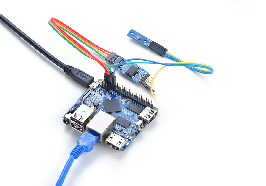
Connection Details:
| Matrix-Photoresistor | |
| GND | NanoPi M1 Pin9 |
| 5V | NanoPi M1 Pin2 |
| S | Matrix-Analog_to_Digital_Converter A0 |
4.2 Connect to NanoPi 2
Refer to the following connection diagram to connect the module to the NanoPi 2:
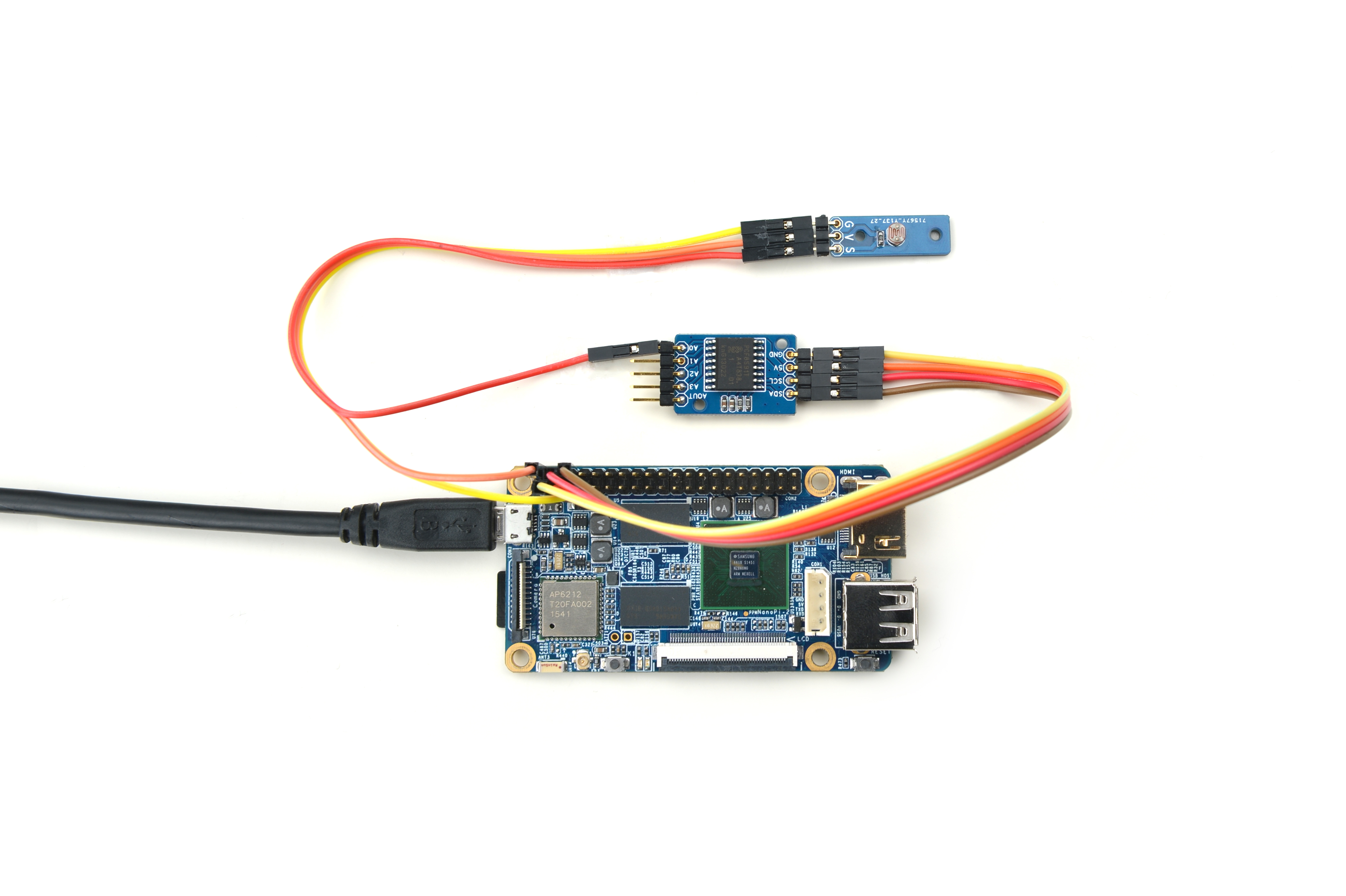
Connection Details:
| Matrix-Photoresistor | |
| GND | NanoPi 2 Pin9 |
| 5V | NanoPi 2 Pin2 |
| S | Matrix-Analog_to_Digital_Converter A0 |
4.3 Connect to NanoPi M2 / NanoPi 2 Fire
Refer to the following connection diagram to connect the module to the NanoPi M2/ NanoPi 2 Fire.
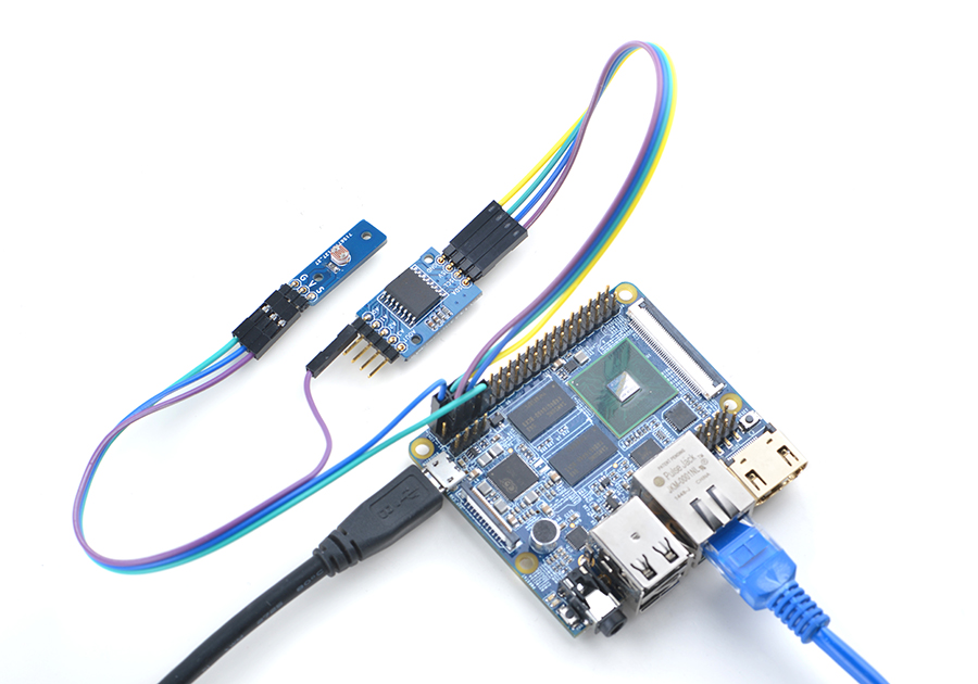
Connection Details:
| Matrix-Photoresistor | |
| GND | NanoPi M2 Pin9 |
| 5V | NanoPi M2 Pin2 |
| S | Matrix-Analog_to_Digital_Converter A0 |
4.4 Connect to NanoPC-T2
Refer to the following connection diagram to connect the module to the NanoPC-T2:
Matrix-Photoresistor_NanoPC-T2
Connection Details:
| Matrix-Potentiometer | |
| GND | NanoPC-T2 USB Host GND |
| 5V | NanoPC-T2 USB Host 5V |
| S | Matrix-Analog_to_Digital_Converter A0 |
5 Compile & Run Test Program
Boot your ARM board with Debian and copy the matrix code:
$ apt-get update && apt-get install git
$ git clone https://github.com/friendlyarm/matrix.git
If your cloning is done successfully a "matrix" directory will be generated.
Compile and install Matrix:
$ cd matrix
$ make && make install
Run test program:
$ matrix-adcNote: this module is not plug and play therefore before running the module please make sure it is connected to an ARM board.
Here is what you should observe:
The channel0 value is 2460The resistance of a photoresistor decreases with increasing incident light intensity.
6 Code Sample
This Matrix code sample can work with all the ARM boards mentioned in this module's wiki. The name of this code sample is "matrix-3_axis_digital_compass". Here is its source code:
int main(int argc, char ** argv)
{
    int i = 0;
    int value = 0;
    int channel = 0;

    if (boardInit() < 0) {
        printf("Fail to init board\n");
        return -1;
    }

    if (argc == 2)
        channel = atoi(argv[1]);
    system("modprobe "DRIVER_MODULE);
    signal(SIGINT, intHandler);
    for (i=0; i<ADC_READ_TIMES; i++) {
        if (pcf8591Read(channel, &value) != -1) {
            printf("The channel%d value is %d\n", channel, value);
        } else {
            printf("Fail to get channel%d value\n", channel);
        }
    }
    system("rmmod "DRIVER_MODULE);

    return 0;
}
For more details about this APIs called in this code sample refer to Matrix API reference manual
7 Resources
8 Update Log
8.1 June-22-2016
- Created English wiki
