Difference between revisions of "Edge-RT300"
From FriendlyELEC WiKi
(→Hardware Spec) |
|||
| (27 intermediate revisions by the same user not shown) | |||
| Line 31: | Line 31: | ||
==Detailed description== | ==Detailed description== | ||
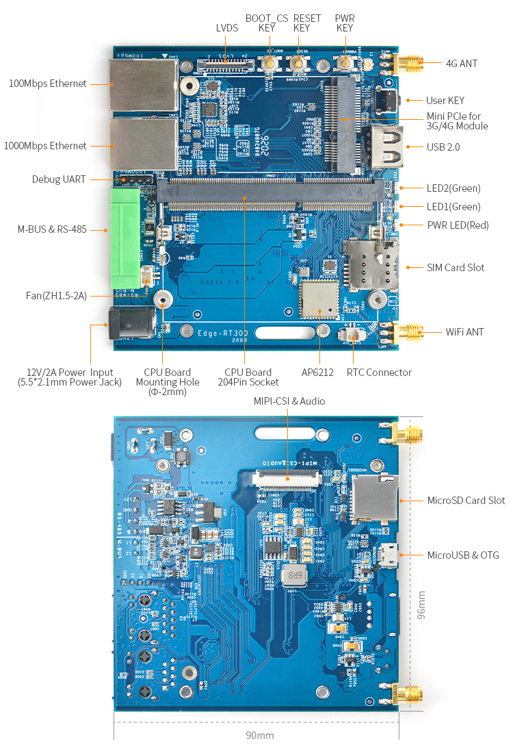
| + | [[File:Edge-RT300-layout.jpg|layout|800px]] | ||
| + | ===RS-485&M-BUS=== | ||
| + | [[File:Edge-RT300-RS485_M-BUS.jpg|RS485&M-BUS]] | ||
| + | <br>Connector Pitch: 3.5mm | ||
| + | {| class="wikitable" | ||
| + | |- | ||
| + | ! style="font-weight:bold;" | Pin# | ||
| + | ! 6 | ||
| + | ! 5 | ||
| + | ! 4 | ||
| + | ! 3 | ||
| + | ! 2 | ||
| + | ! 1 | ||
| + | |- | ||
| + | | style="font-weight:bold;" | Name | ||
| + | | L2 | ||
| + | | L1 | ||
| + | | B | ||
| + | | A | ||
| + | | GND | ||
| + | | 12V | ||
| + | |- | ||
| + | | style="font-weight:bold;" | Description | ||
| + | | M-BUS L2 | ||
| + | | M-BUS L1 | ||
| + | | RS-485 B | ||
| + | | RS-485 A | ||
| + | | GND | ||
| + | | 12V Power input(optional) | ||
| + | |} | ||
| + | '''RS-485''' | ||
| + | * Use SN65HVD3082EDR RS-485 Transceivers, support 1/8 Unit Load—Up to 256 Nodes on a Bus, Bus-Pin ESD Protection Up to 15 kV. | ||
| + | * baud rate: 0.2Mbps MAX | ||
| + | * Connetected to UART2. | ||
| + | '''M-Bus Master''' | ||
| + | * Connetected to UART3. | ||
| + | * support up to 40 slaves. | ||
| + | * baud rate: 2400~9600 | ||
| + | * about M-bus, refer to https://m-bus.com/documentation | ||
| + | |||
| + | ===MIPI-CSI&Audio=== | ||
| + | '''Pinout''' | ||
| + | {| class="wikitable" | ||
| + | |- | ||
| + | ! Pin# | ||
| + | ! Name | ||
| + | ! Description | ||
| + | |- | ||
| + | | 1 | ||
| + | | 3.3V out | ||
| + | | 3.3V Power Output | ||
| + | |- | ||
| + | | 2 | ||
| + | | 3.3V out | ||
| + | | 3.3V Power Output | ||
| + | |- | ||
| + | | 3 | ||
| + | | GND | ||
| + | | Ground | ||
| + | |- | ||
| + | | 4 | ||
| + | | I2C0_SDA | ||
| + | | I2C bus0 data | ||
| + | |- | ||
| + | | 5 | ||
| + | | I2C0_SCL | ||
| + | | I2C bus0 clock | ||
| + | |- | ||
| + | | 6 | ||
| + | | GND | ||
| + | | Ground | ||
| + | |- | ||
| + | | 7 | ||
| + | | AUDIO_GND | ||
| + | | Audio Common terminal | ||
| + | |- | ||
| + | | 8 | ||
| + | | HP_R | ||
| + | | Headphone output R | ||
| + | |- | ||
| + | | 9 | ||
| + | | HP_L | ||
| + | | Headphone output L | ||
| + | |- | ||
| + | | 10 | ||
| + | | MICIN_P | ||
| + | | Microphone input P | ||
| + | |- | ||
| + | | 11 | ||
| + | | GND | ||
| + | | Ground | ||
| + | |- | ||
| + | | 12 | ||
| + | | GPIOB23 | ||
| + | | GPIO | ||
| + | |- | ||
| + | | 13 | ||
| + | | GPIOC2 | ||
| + | | GPIO | ||
| + | |- | ||
| + | | 14 | ||
| + | | GPIOC13/PWM1 | ||
| + | | GPIO or PWM | ||
| + | |- | ||
| + | | 15 | ||
| + | | GND | ||
| + | | Ground | ||
| + | |- | ||
| + | | 16 | ||
| + | | GPIOB27/HP_DETECT | ||
| + | | GPIO, or Headphone insert detect | ||
| + | |- | ||
| + | | 17 | ||
| + | | /NC | ||
| + | | | ||
| + | |- | ||
| + | | 18 | ||
| + | | GND | ||
| + | | Ground | ||
| + | |- | ||
| + | | 19 | ||
| + | | /NC | ||
| + | | | ||
| + | |- | ||
| + | | 20 | ||
| + | | /NC | ||
| + | | | ||
| + | |- | ||
| + | | 21 | ||
| + | | GND | ||
| + | | Ground | ||
| + | |- | ||
| + | | 22 | ||
| + | | MIPI_CSI0_D1N | ||
| + | | rowspan="2" | MIPI CSI Data0 | ||
| + | |- | ||
| + | | 23 | ||
| + | | MIPI_CSI0_D1P | ||
| + | |- | ||
| + | | 24 | ||
| + | | GND | ||
| + | | Ground | ||
| + | |- | ||
| + | | 25 | ||
| + | | MIPI_CSI0_D0N | ||
| + | | rowspan="2" | MIPI CSI Data1 | ||
| + | |- | ||
| + | | 26 | ||
| + | | MIPI_CSI0_D0P | ||
| + | |- | ||
| + | | 27 | ||
| + | | GND | ||
| + | | Ground | ||
| + | |- | ||
| + | | 28 | ||
| + | | MIPI_CSI0_CLKN | ||
| + | | rowspan="2" | MIPI CSI Clock | ||
| + | |- | ||
| + | | 29 | ||
| + | | MIPI_CSI0_CLKP | ||
| + | |- | ||
| + | | 30 | ||
| + | | GND | ||
| + | | Ground | ||
| + | |} | ||
| + | |||
| + | ===LVDS=== | ||
| + | {| class="wikitable" | ||
| + | |- | ||
| + | ! Pin# | ||
| + | ! Name | ||
| + | ! Description | ||
| + | |- | ||
| + | | 1 | ||
| + | | 5V | ||
| + | | 5V Power output | ||
| + | |- | ||
| + | | 2 | ||
| + | | 5V | ||
| + | | 5V Power output | ||
| + | |- | ||
| + | | 3 | ||
| + | | 5V | ||
| + | | 5V Power output | ||
| + | |- | ||
| + | | 4 | ||
| + | | LVDS_Y0M | ||
| + | | LVDS D0- | ||
| + | |- | ||
| + | | 5 | ||
| + | | LVDS_Y0P | ||
| + | | LVDS D0+ | ||
| + | |- | ||
| + | | 6 | ||
| + | | GND | ||
| + | | Ground | ||
| + | |- | ||
| + | | 7 | ||
| + | | LVDS_Y1M | ||
| + | | LVDS D1- | ||
| + | |- | ||
| + | | 8 | ||
| + | | LVDS_Y1P | ||
| + | | LVDS D1+ | ||
| + | |- | ||
| + | | 9 | ||
| + | | GND | ||
| + | | Ground | ||
| + | |- | ||
| + | | 10 | ||
| + | | LVDS_Y2M | ||
| + | | LVDS D2- | ||
| + | |- | ||
| + | | 11 | ||
| + | | LVDS_Y2P | ||
| + | | LVDS D2+ | ||
| + | |- | ||
| + | | 12 | ||
| + | | GND | ||
| + | | Ground | ||
| + | |- | ||
| + | | 13 | ||
| + | | LVDS_CLKM | ||
| + | | LVDS Clock- | ||
| + | |- | ||
| + | | 14 | ||
| + | | LVDS_CLKP | ||
| + | | LVDS Clock+ | ||
| + | |- | ||
| + | | 15 | ||
| + | | GND | ||
| + | | Ground | ||
| + | |- | ||
| + | | 16 | ||
| + | | LVDS_Y3M | ||
| + | | LVDS D3- | ||
| + | |- | ||
| + | | 17 | ||
| + | | LVDS_Y3P | ||
| + | | LVDS D3+ | ||
| + | |- | ||
| + | | 18 | ||
| + | | GND | ||
| + | | Ground | ||
| + | |- | ||
| + | | 19 | ||
| + | | /NC | ||
| + | | | ||
| + | |- | ||
| + | | 20 | ||
| + | | GND | ||
| + | | Ground | ||
| + | |- | ||
| + | | 21 | ||
| + | | LCD_SCL | ||
| + | | rowspan="3" | for touch pannel,and backlight control,etc | ||
| + | |- | ||
| + | | 22 | ||
| + | | LCD_SDA | ||
| + | |- | ||
| + | | 23 | ||
| + | | LCD_TPINT | ||
| + | |- | ||
| + | | 24 | ||
| + | | GND | ||
| + | | Ground | ||
| + | |} | ||
| + | |||
| + | ===USB Host=== | ||
| + | The 10/100Mbps USB-LAN, MiniPCIe and USB Type-A share the USB 2.0 480Mbps bandwidth. | ||
| + | |||
| + | ===User LEDs=== | ||
| + | {| class="wikitable" | ||
| + | |- | ||
| + | ! LED | ||
| + | ! LED1 | ||
| + | ! LED2 | ||
| + | |- | ||
| + | | GPIO | ||
| + | | GPIOB30 | ||
| + | | GPIOB31 | ||
| + | |- | ||
| + | | ON logic | ||
| + | | 0 | ||
| + | | 0 | ||
| + | |} | ||
| + | |||
| + | ===User Key=== | ||
| + | This key is connected to AliveGPIO3 of the SoC. | ||
| + | |||
| + | ===RJ45 Ethernet=== | ||
| + | 10/100/1000Mbps Ethernet support WOL(Wake On Lan) function. The following steps shows how to enable this function. | ||
| + | <br>a) disable NetworkManager first | ||
| + | <br>b) install ethtool | ||
| + | <br>c) add following lines to /etc/network/interfaces | ||
| + | auto eth0 | ||
| + | iface eth0 inet dhcp | ||
| + | ethernet-wol g | ||
| + | |||
| + | ===debug console=== | ||
| + | The baud rate is 115200bps. | ||
| + | |||
| + | ===Power Supply=== | ||
| + | {| class="wikitable" | ||
| + | |- | ||
| + | ! Load to | ||
| + | ! MiniPCIe | ||
| + | ! USB Type-A | ||
| + | ! USB OTG | ||
| + | ! LVDS | ||
| + | ! MIPI-CSI&Audio | ||
| + | |- | ||
| + | | Output Voltage | ||
| + | | 3.5V | ||
| + | | 5V | ||
| + | | 5V | ||
| + | | 5V | ||
| + | | 3.3V | ||
| + | |- | ||
| + | | Recommended Load | ||
| + | | 2A | ||
| + | | 0.5A | ||
| + | | 0.5A | ||
| + | | 0.3A | ||
| + | | 0.3A | ||
| + | |- | ||
| + | | Max allowed Load | ||
| + | | 3A | ||
| + | | 1A | ||
| + | | 1A | ||
| + | | 0.5A | ||
| + | | 0.5A | ||
| + | |- | ||
| + | | | ||
| + | | colspan="5" | 10W Max totally | ||
| + | |} | ||
| + | {{S5Pxx18HWfiles|Edge-RT300}} | ||
Latest revision as of 07:51, 12 August 2020
Contents
[hide]1 Introduction
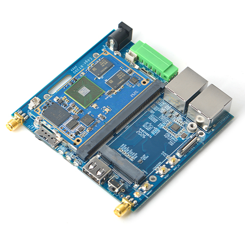
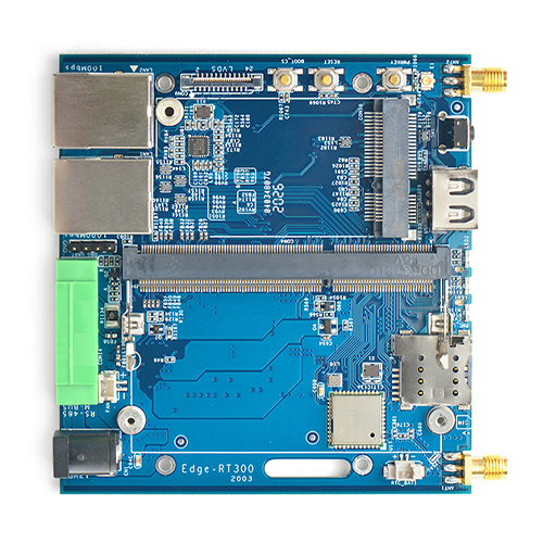
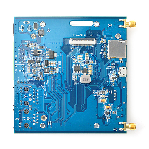
- The Edge-RT300 is designed and developed by FriendlyELEC for professional and enterprise users. It is based on SOM-4418.
- The Edge-RT300 has rich interconnection interfaces, including dual RJ45 ethernet ports, Wi-Fi, BT, 4G, RS-485 and M-BUS master, which makes it suitable for IoT applications.
2 Hardware Spec
- CPU Board: SOM-4418
- SoC:Samsung S5P4418 Quad Core Cortex-A9 with dynamic frequency scaling up to 1.4G Hz
- System Memory:1GB 32bit DDR3 RAM
- eMMC:8GB
- Connectivity:
- One 10/100/1000Mbps Ethernet Port (Native MAC, PHY is RTL8211E) with unique MAC, support WOL(Wake On Lan)
- One 10/1000Mbps Ethernet Port (USB to LAN, RTL852B)
- One MiniPCIe Socket & MicroSIM Card Slot for 4G module
- One 802.11b/g/n Wi-Fi & Bluetooth 4.0 (AP6212)
- One TTL to RS-485 converter
- One TTL to wired M-BUS Master converter
- Video Input: MIPI-CSI
- Video Output: LVDS
- Audio: 2-Chanel headphone output, one Microphone input
- USB: 1 x USB 2.0 Host(Via USB Hub), 1 x USB 2.0 OTG
- LED: 1 x power LED , 2 x User LED
- Key: 1 x User Key, PowerKey, Reset key, SD/MMC Boot Select key
- Other Resource: 1 x MicroSD, RTC battery input, 2-pin ZH connector for 5V cooling fan
- Power: DC 12V/2A
- PCB: Four Layer, 96 mm x 90 mm x 1.6mm
- Working Temperature: -40℃ to 70℃
3 Detailed description
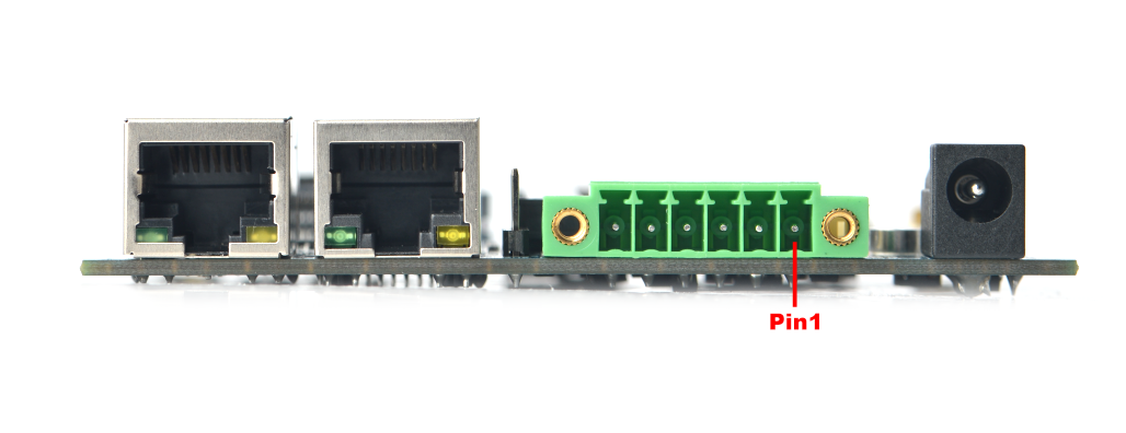
3.1 RS-485&M-BUS
| Pin# | 6 | 5 | 4 | 3 | 2 | 1 |
|---|---|---|---|---|---|---|
| Name | L2 | L1 | B | A | GND | 12V |
| Description | M-BUS L2 | M-BUS L1 | RS-485 B | RS-485 A | GND | 12V Power input(optional) |
RS-485
- Use SN65HVD3082EDR RS-485 Transceivers, support 1/8 Unit Load—Up to 256 Nodes on a Bus, Bus-Pin ESD Protection Up to 15 kV.
- baud rate: 0.2Mbps MAX
- Connetected to UART2.
M-Bus Master
- Connetected to UART3.
- support up to 40 slaves.
- baud rate: 2400~9600
- about M-bus, refer to https://m-bus.com/documentation
3.2 MIPI-CSI&Audio
Pinout
| Pin# | Name | Description |
|---|---|---|
| 1 | 3.3V out | 3.3V Power Output |
| 2 | 3.3V out | 3.3V Power Output |
| 3 | GND | Ground |
| 4 | I2C0_SDA | I2C bus0 data |
| 5 | I2C0_SCL | I2C bus0 clock |
| 6 | GND | Ground |
| 7 | AUDIO_GND | Audio Common terminal |
| 8 | HP_R | Headphone output R |
| 9 | HP_L | Headphone output L |
| 10 | MICIN_P | Microphone input P |
| 11 | GND | Ground |
| 12 | GPIOB23 | GPIO |
| 13 | GPIOC2 | GPIO |
| 14 | GPIOC13/PWM1 | GPIO or PWM |
| 15 | GND | Ground |
| 16 | GPIOB27/HP_DETECT | GPIO, or Headphone insert detect |
| 17 | /NC | |
| 18 | GND | Ground |
| 19 | /NC | |
| 20 | /NC | |
| 21 | GND | Ground |
| 22 | MIPI_CSI0_D1N | MIPI CSI Data0 |
| 23 | MIPI_CSI0_D1P | |
| 24 | GND | Ground |
| 25 | MIPI_CSI0_D0N | MIPI CSI Data1 |
| 26 | MIPI_CSI0_D0P | |
| 27 | GND | Ground |
| 28 | MIPI_CSI0_CLKN | MIPI CSI Clock |
| 29 | MIPI_CSI0_CLKP | |
| 30 | GND | Ground |
3.3 LVDS
| Pin# | Name | Description |
|---|---|---|
| 1 | 5V | 5V Power output |
| 2 | 5V | 5V Power output |
| 3 | 5V | 5V Power output |
| 4 | LVDS_Y0M | LVDS D0- |
| 5 | LVDS_Y0P | LVDS D0+ |
| 6 | GND | Ground |
| 7 | LVDS_Y1M | LVDS D1- |
| 8 | LVDS_Y1P | LVDS D1+ |
| 9 | GND | Ground |
| 10 | LVDS_Y2M | LVDS D2- |
| 11 | LVDS_Y2P | LVDS D2+ |
| 12 | GND | Ground |
| 13 | LVDS_CLKM | LVDS Clock- |
| 14 | LVDS_CLKP | LVDS Clock+ |
| 15 | GND | Ground |
| 16 | LVDS_Y3M | LVDS D3- |
| 17 | LVDS_Y3P | LVDS D3+ |
| 18 | GND | Ground |
| 19 | /NC | |
| 20 | GND | Ground |
| 21 | LCD_SCL | for touch pannel,and backlight control,etc |
| 22 | LCD_SDA | |
| 23 | LCD_TPINT | |
| 24 | GND | Ground |
3.4 USB Host
The 10/100Mbps USB-LAN, MiniPCIe and USB Type-A share the USB 2.0 480Mbps bandwidth.
3.5 User LEDs
| LED | LED1 | LED2 |
|---|---|---|
| GPIO | GPIOB30 | GPIOB31 |
| ON logic | 0 | 0 |
3.6 User Key
This key is connected to AliveGPIO3 of the SoC.
3.7 RJ45 Ethernet
10/100/1000Mbps Ethernet support WOL(Wake On Lan) function. The following steps shows how to enable this function.
a) disable NetworkManager first
b) install ethtool
c) add following lines to /etc/network/interfaces
   auto eth0
   iface eth0 inet dhcp
   ethernet-wol g
3.8 debug console
The baud rate is 115200bps.
3.9 Power Supply
| Load to | MiniPCIe | USB Type-A | USB OTG | LVDS | MIPI-CSI&Audio |
|---|---|---|---|---|---|
| Output Voltage | 3.5V | 5V | 5V | 5V | 3.3V |
| Recommended Load | 2A | 0.5A | 0.5A | 0.3A | 0.3A |
| Max allowed Load | 3A | 1A | 1A | 0.5A | 0.5A |
| 10W Max totally | |||||
4 Schematics & Mechanical drawing
- PCB Dimension(Edge-RT300_2003_dxf.zip)
- Schematic(Edge-RT300-2003-Schematic.pdf)
