Difference between revisions of "Matrix - Analog to Digital Converter"
(→Basic Device Operation) |
(→Applications) |
||
| (25 intermediate revisions by 2 users not shown) | |||
| Line 18: | Line 18: | ||
* 2.54 mm spacing pin | * 2.54 mm spacing pin | ||
* PCB dimension (mm): 16 x 24 | * PCB dimension (mm): 16 x 24 | ||
| − | [[File:adcpcb.png|frameless|400px| | + | [[File:adcpcb.png|frameless|400px|Analog to Digital PCB]] |
* Pin Description: | * Pin Description: | ||
| Line 51: | Line 51: | ||
3. The on-chip D/A converter and a high-gain comparator are used temporarily during an A/D conversion cycle. An A/D conversion cycle is always started after sending a valid read mode address to a PCF8591 device. The A/D conversion cycle is triggered at the trailing edge of the acknowledge clock pulse and is executed while transmitting the result of the previous conversion。 <br> | 3. The on-chip D/A converter and a high-gain comparator are used temporarily during an A/D conversion cycle. An A/D conversion cycle is always started after sending a valid read mode address to a PCF8591 device. The A/D conversion cycle is triggered at the trailing edge of the acknowledge clock pulse and is executed while transmitting the result of the previous conversion。 <br> | ||
| − | |||
| − | |||
| − | |||
| − | |||
| − | |||
| − | |||
| − | + | ==Applications== | |
| + | ===Connect to NanoPi M1=== | ||
| + | Refer to the following connection diagram to connect the module to the NanoPi M1<br> | ||
| + | [[File:Matrix-Analog_to_Digital_Converter_nanopi_m1.jpg|frameless|600px|Matrix-Analog_to_Digital_Converter_nanopi_m1]] | ||
| + | |||
| + | Connection Details: | ||
| + | {| class="wikitable" | ||
| + | |- | ||
| + | |Matrix-Analog_to_Digital_Converter || NanoPi M1 | ||
| + | |- | ||
| + | |SDA || Pin3 | ||
| + | |- | ||
| + | |SCL || Pin5 | ||
| + | |- | ||
| + | |5V || Pin4 | ||
| + | |- | ||
| + | |GND || Pin6 | ||
| + | |} | ||
| + | |||
| + | ===Connect to NanoPi 2=== | ||
| + | Refer to the following connection diagram to connect the module to the NanoPi 2:<br> | ||
| + | [[File:Matrix-Analog_to_Digital_Converter_nanopi_2.jpg|frameless|600px|Matrix-Analog_to_Digital_Converter_nanopi_2]] | ||
| + | |||
| + | Connection Details: | ||
| + | {| class="wikitable" | ||
| + | |- | ||
| + | |Matrix-Analog_to_Digital_Converter || NanoPi 2 | ||
| + | |- | ||
| + | |SDA || Pin3 | ||
| + | |- | ||
| + | |SCL || Pin5 | ||
| + | |- | ||
| + | |5V || Pin4 | ||
| + | |- | ||
| + | |GND || Pin6 | ||
| + | |} | ||
| + | |||
| + | ===Connect to NanoPi M2 / NanoPi 2 Fire=== | ||
| + | Refer to the following connection diagram to connect the module to the NanoPi M2/ NanoPi 2 Fire:<br> | ||
| + | [[File:Matrix-Analog_to_Digital_Converter_nanopi_M2.jpg|frameless|600px|Matrix-Analog_to_Digital_Converter_nanopi_M2]] | ||
| + | |||
| + | Connection Details: | ||
| + | {| class="wikitable" | ||
| + | |- | ||
| + | |Matrix-Analog_to_Digital_Converter || NanoPi M2 | ||
| + | |- | ||
| + | |SDA || Pin3 | ||
| + | |- | ||
| + | |SCL || Pin5 | ||
| + | |- | ||
| + | |5V || Pin4 | ||
| + | |- | ||
| + | |GND || Pin6 | ||
| + | |} | ||
| + | |||
| + | ===Connect to NanoPC-T2=== | ||
| + | Refer to the following connection diagram to connect the module to the NanoPC-T2<br> | ||
| + | [[File:Matrix-Analog_to_Digital_Converter_NanoPC-T2.jpg|frameless|600px|Matrix-Analog_to_Digital_Converter_NanoPC-T2]] | ||
| + | |||
| + | Connection Details: | ||
| + | {| class="wikitable" | ||
| + | |- | ||
| + | |Matrix-Analog_to_Digital_Converter || NanoPC-T2 | ||
| + | |- | ||
| + | |SDA || Pin6 | ||
| + | |- | ||
| + | |SCL || Pin5 | ||
| + | |- | ||
| + | |5V || Pin29 | ||
| + | |- | ||
| + | |GND || Pin30 | ||
| + | |} | ||
| + | |||
| + | ==Compile & Run Test Program== | ||
| + | Boot your ARM board with Debian and copy the matrix code: | ||
| + | <syntaxhighlight lang="bash"> | ||
| + | $ apt-get update && apt-get install git | ||
| + | $ git clone https://github.com/friendlyarm/matrix.git | ||
| + | </syntaxhighlight> | ||
| + | If your cloning is done successfully a "matrix" directory will be generated. | ||
| + | |||
| + | Compile and install Matrix: | ||
| + | <syntaxhighlight lang="bash"> | ||
| + | $ cd matrix | ||
| + | $ make && make install | ||
| + | </syntaxhighlight> | ||
| + | |||
| + | Run test program: | ||
| + | <syntaxhighlight lang="bash"> | ||
| + | $ matrix-adc | ||
| + | </syntaxhighlight> | ||
| + | Note: this module is not plug and play therefore before running the module please make sure it is connected to an ARM board.<br> | ||
| + | Here is what you should observe:<br> | ||
| + | <syntaxhighlight lang="bash"> | ||
| + | The channel0 value is 2460 | ||
| + | </syntaxhighlight> | ||
| + | When Channel 0 is connected to 5V its value reaches the maximum: 2550. When it is grounded its value is 0. | ||
| + | |||
| + | ==Code Sample== | ||
| + | This Matrix code sample can work with all the ARM boards mentioned in this module's wiki. The name of this code sample is "matrix-analog_to_digital_converter". Here is its source code: | ||
| + | <syntaxhighlight lang="c"> | ||
| + | int main(int argc, char ** argv) | ||
| + | { | ||
| + | int i = 0; | ||
| + | int value = 0; | ||
| + | int channel = 0; | ||
| + | |||
| + | if (boardInit() < 0) { | ||
| + | printf("Fail to init board\n"); | ||
| + | return -1; | ||
| + | } | ||
| + | |||
| + | if (argc == 2) | ||
| + | channel = atoi(argv[1]); | ||
| + | system("modprobe "DRIVER_MODULE); | ||
| + | signal(SIGINT, intHandler); | ||
| + | for (i=0; i<ADC_READ_TIMES; i++) { | ||
| + | if (pcf8591Read(channel, &value) != -1) { | ||
| + | printf("The channel%d value is %d\n", channel, value); | ||
| + | } else { | ||
| + | printf("Fail to get channel%d value\n", channel); | ||
| + | } | ||
| + | } | ||
| + | system("rmmod "DRIVER_MODULE); | ||
| + | |||
| + | return 0; | ||
| + | } | ||
| + | </syntaxhighlight> | ||
| + | For more details about this APIs called in this code sample refer to [[Matrix API reference manual]] <br> | ||
| + | |||
| + | |||
| + | <!--- | ||
| + | ==Download Matrix Source Code== | ||
| + | All the matrix modules' code samples are open source. They are maintained on GitHub - https://github.com/friendlyarm/matrix.git <br> | ||
| + | Each branch in this hub contains the matrix modules' code samples for a board that the matrix modules can work with.<br> | ||
| + | * The nanopi branch contains the matrix modules' code samples for the NanoPi | ||
| + | * The nanopi 2 branch contains the matrix modules' code samples for the NanoPi 2 | ||
| + | * The tiny4412 branch contains the matrix modules' code samples for the Tiny4412 | ||
| + | * The raspberrypi branch contains the matrix modules' code samples for the RaspberryPi | ||
| + | |||
| + | Please follow the steps below to get the source code: <br> | ||
| + | Install the git utility on a PC running Ubuntu14.04 | ||
<syntaxhighlight lang="bash"> | <syntaxhighlight lang="bash"> | ||
$ sudo apt-get install git | $ sudo apt-get install git | ||
</syntaxhighlight> | </syntaxhighlight> | ||
| − | + | Clone the matrix code from GitHub | |
<syntaxhighlight lang="bash"> | <syntaxhighlight lang="bash"> | ||
| − | $ git clone | + | $ git clone https://github.com/friendlyarm/matrix.git |
| + | </syntaxhighlight> | ||
| + | If this is successful a "matrix" directory will be generated, which will contain all the matrix modules' code samples. | ||
| + | |||
| + | ==Connect to NanoPi 2== | ||
| + | ===Hardware Connection=== | ||
| + | Please refer to the following connection diagram to connect the Matrix-Analog_to_Digital_Converter to the NanoPi 2:<br> | ||
| + | [[File:Matrix-Analog_to_Digital_Converter_nanopi_2.jpg|frameless|600px|Matrix-Analog_to_Digital_Converter_nanopi_2]] | ||
| + | |||
| + | Connection Details: | ||
| + | {| class="wikitable" | ||
| + | |- | ||
| + | |Matrix-Analog_to_Digital_Converter || NanoPi 2 | ||
| + | |- | ||
| + | |SDA || Pin3 | ||
| + | |- | ||
| + | |SCL || Pin5 | ||
| + | |- | ||
| + | |5V || Pin4 | ||
| + | |- | ||
| + | |GND || Pin6 | ||
| + | |} | ||
| + | |||
| + | ===Compile Test Program=== | ||
| + | Please login the matrix hub and enter the nanopi2 branch | ||
| + | <syntaxhighlight lang="bash"> | ||
| + | $ cd matrix | ||
| + | $ git checkout nanopi2 | ||
| + | </syntaxhighlight> | ||
| + | |||
| + | Compile the matrix code | ||
| + | <syntaxhighlight lang="bash"> | ||
| + | $ make CROSS_COMPILE=arm-linux- clean | ||
| + | $ make CROSS_COMPILE=arm-linux- | ||
| + | $ make CROSS_COMPILE=arm-linux- install | ||
| + | </syntaxhighlight> | ||
| + | Note: please make sure to install the cross compiler "arm-linux-gcc-4.9.3" on your PC, which is used to compile files for the NanoPi2.<br> | ||
| + | Generated library files are under the "install/lib" directory. Applications are under the "install/usr/bin" directory. The test program for the "Matrix-Analog_to_Digital_Converter" module is "matrix-adc".<br> | ||
| + | The driver is under the modules directory and its source code is in github: https://github.com/friendlyarm/linux-3.4.y.git <br> | ||
| + | |||
| + | ===Run Test Program=== | ||
| + | Please insert a TF card which is flashed with Debian to a Linux host and mount its boot and rootfs sections.<br> | ||
| + | We assume the rootfs is mounted to /media/rootfs then please run the following commands to copy the driver, library and test program to the card.<br> | ||
| + | <syntaxhighlight lang="bash"> | ||
| + | $ cp modules /media/rootfs/ -r | ||
| + | $ cp install/lib/* /media/rootfs/lib/ -d | ||
| + | $ cp install/usr/bin/* /media/rootfs/usr/bin/ | ||
| + | </syntaxhighlight> | ||
| + | |||
| + | Insert this TF card to your NanoPi 2, power on and run the following commands.<br> | ||
| + | <syntaxhighlight lang="bash"> | ||
| + | $ cd /modules | ||
| + | $ insmod pcf8591.ko | ||
| + | </syntaxhighlight> | ||
| + | |||
| + | Start the matrix-adc program.<br> | ||
| + | <syntaxhighlight lang="bash"> | ||
| + | $ matrix-adc | ||
| + | </syntaxhighlight> | ||
| + | Note: this module is not plug and play therefore before running the module please make sure it is connected to a NanoPi 2.<br> | ||
| + | Here is what you should expect:<br> | ||
| + | [[File:matrix-adc_result.png|frameless||matrix-adc_result]] <br> | ||
| + | The program reads Channel 0's value | ||
| + | |||
| + | ===Code Sample=== | ||
| + | <syntaxhighlight lang="c"> | ||
| + | int main(int argc, char ** argv) | ||
| + | { | ||
| + | int i = 0; | ||
| + | int value = 0; | ||
| + | int channel = 0; | ||
| + | |||
| + | if (argc == 2) { | ||
| + | channel = atoi(argv[1]); | ||
| + | } | ||
| + | |||
| + | for (i=0; i<ADC_READ_TIMES; i++) { | ||
| + | if (pcf8591Read(channel, &value) != -1) { | ||
| + | printf("channel%d value=%d\n", channel, value); | ||
| + | } else { | ||
| + | printf("Fail to get channel%d value\n", channel); | ||
| + | } | ||
| + | usleep(10000); | ||
| + | } | ||
| + | return 0; | ||
| + | } | ||
</syntaxhighlight> | </syntaxhighlight> | ||
| − | |||
| − | == | + | ==Connect to NanoPi== |
| − | === | + | ===Preparations=== |
| − | + | Please install a Debian on a NanoPi and an appropriate cross compiler on a PC. Please refer to wiki:[[NanoPi/zh|NanoPi]] <br> | |
| − | + | Compile a NanoPi kernel. Note: please use the kernel's source code from the nanopi-v4.1.y-matrix branch.<br> | |
| − | + | ||
<syntaxhighlight lang="bash"> | <syntaxhighlight lang="bash"> | ||
$ git clone https://github.com/friendlyarm/linux-4.x.y.git | $ git clone https://github.com/friendlyarm/linux-4.x.y.git | ||
| Line 83: | Line 301: | ||
</syntaxhighlight> | </syntaxhighlight> | ||
| − | === | + | ===Hardware Connection=== |
| − | + | Please refer to the following connection diagram to connect the Matrix-Analog_to_Digital_Converter to the NanoPi <br> | |
[[File:matrix-analog_to_digital_converter_nanopi.jpg|frameless|600px|matrix-analog_to_digital_converter_nanopi]] | [[File:matrix-analog_to_digital_converter_nanopi.jpg|frameless|600px|matrix-analog_to_digital_converter_nanopi]] | ||
| − | + | Connection Details: | |
{| class="wikitable" | {| class="wikitable" | ||
|- | |- | ||
| Line 101: | Line 319: | ||
|} | |} | ||
| − | === | + | ===Compile Test Program=== |
| − | + | Please login the matrix hub and enter the nanopi branch | |
<syntaxhighlight lang="bash"> | <syntaxhighlight lang="bash"> | ||
$ cd matrix | $ cd matrix | ||
| Line 108: | Line 326: | ||
</syntaxhighlight> | </syntaxhighlight> | ||
| − | + | Compile the matrix code | |
<syntaxhighlight lang="bash"> | <syntaxhighlight lang="bash"> | ||
$ make CROSS_COMPILE=arm-linux- clean | $ make CROSS_COMPILE=arm-linux- clean | ||
| Line 114: | Line 332: | ||
$ make CROSS_COMPILE=arm-linux- install | $ make CROSS_COMPILE=arm-linux- install | ||
</syntaxhighlight> | </syntaxhighlight> | ||
| − | + | Note: please make sure to install the cross compiler "arm-linux-gcc-4.4.3" on your PC, which is used to compile files for the NanoPi-Debian.<br> | |
| − | + | Generated library files are under the "install/lib" directory. Applications are under the "install/usr/bin" directory. The test program for the "Matrix-Analog_to_Digital_Converter" module is "matrix-adc".<br> | |
| − | === | + | ===Run Test Program=== |
| − | + | Please copy the library files and test program to the NanoPi | |
<syntaxhighlight lang="bash"> | <syntaxhighlight lang="bash"> | ||
$ cp install/usr/bin/* nanopi_rootfs/usr/bin/ | $ cp install/usr/bin/* nanopi_rootfs/usr/bin/ | ||
| Line 124: | Line 342: | ||
</syntaxhighlight> | </syntaxhighlight> | ||
| − | + | Power on the NanoPi and run the following command in Debian's terminal <br> | |
| − | + | Note: this module is not plug and play therefore before running the module please make sure it is connected to a NanoPi. | |
<syntaxhighlight lang="bash"> | <syntaxhighlight lang="bash"> | ||
| − | $ matrix- | + | $ matrix-adc |
</syntaxhighlight> | </syntaxhighlight> | ||
| − | === | + | ===Code Sample=== |
<syntaxhighlight lang="c"> | <syntaxhighlight lang="c"> | ||
int main(int argc, char ** argv) | int main(int argc, char ** argv) | ||
| Line 160: | Line 378: | ||
</syntaxhighlight> | </syntaxhighlight> | ||
| − | == | + | ==Connect to Tiny4412== |
| − | === | + | ===Preparations=== |
| − | + | Please refer to the Tiny4412's user's manual to install a UbuntuCore on the Tiny4412 and install an appropriate cross compiler on a PC.<br> | |
| − | + | Note: only the Tiny4412SDK-1506 carrier board can work with this module. | |
| − | === | + | ===Hardware Connection=== |
| − | + | Please refer to the following diagram to connect the Matrix-Analog_to_Digital_Converter to the Tiny4412 <br> | |
[[File:matrix-analog_to_digital_converter_tiny4412.jpg|frameless|600px|matrix-analog_to_digital_converter_tiny4412]] | [[File:matrix-analog_to_digital_converter_tiny4412.jpg|frameless|600px|matrix-analog_to_digital_converter_tiny4412]] | ||
| − | + | Connection Details: | |
{| class="wikitable" | {| class="wikitable" | ||
|- | |- | ||
| Line 183: | Line 401: | ||
|} | |} | ||
| − | === | + | ===Compile Test Program=== |
| − | + | Please login the Matrix hub and enter the matrix-tiny4412 branch | |
<syntaxhighlight lang="bash"> | <syntaxhighlight lang="bash"> | ||
$ cd matrix | $ cd matrix | ||
| Line 190: | Line 408: | ||
</syntaxhighlight> | </syntaxhighlight> | ||
| − | + | Compile the matrix code | |
<syntaxhighlight lang="bash"> | <syntaxhighlight lang="bash"> | ||
$ make CROSS_COMPILE=arm-linux-gnueabihf- clean | $ make CROSS_COMPILE=arm-linux-gnueabihf- clean | ||
| Line 196: | Line 414: | ||
$ make CROSS_COMPILE=arm-linux-gnueabihf- install | $ make CROSS_COMPILE=arm-linux-gnueabihf- install | ||
</syntaxhighlight> | </syntaxhighlight> | ||
| − | + | Note: please make sure to install the cross compiler "arm-linux-gnueabihf-gcc-4.7.3" on your PC, which is used to compile files for the Tiny4412-UbuntuCore. <br> | |
| − | + | Generated library files are under the "install/lib" directory. Applications are under the "install/usr/bin" directory. The test program for the "Matrix-Analog_to_Digital_Converter" module is "matrix-adc". | |
| − | === | + | ===Run Test Program=== |
| − | + | Please copy the library files and test program to the Tiny4412 | |
<syntaxhighlight lang="bash"> | <syntaxhighlight lang="bash"> | ||
$ cp install/usr/bin/* tiny4412_rootfs/usr/bin/ | $ cp install/usr/bin/* tiny4412_rootfs/usr/bin/ | ||
| Line 206: | Line 424: | ||
</syntaxhighlight> | </syntaxhighlight> | ||
| − | + | Power on the Tiny4412 and run the following command in UbuntuCore's terminal | |
<syntaxhighlight lang="bash"> | <syntaxhighlight lang="bash"> | ||
| − | $ matrix- | + | $ matrix-adc |
</syntaxhighlight> | </syntaxhighlight> | ||
| − | === | + | ===Code Sample=== |
<syntaxhighlight lang="c"> | <syntaxhighlight lang="c"> | ||
int main(int argc, char ** argv) | int main(int argc, char ** argv) | ||
| Line 241: | Line 459: | ||
</syntaxhighlight> | </syntaxhighlight> | ||
| − | == | + | ==Connect to RaspberryPi== |
| − | == | + | ==Connect to Arduino== |
| + | ---> | ||
| − | == | + | |
| + | ==Resources== | ||
[http://www.nxp.com/documents/data_sheet/PCF8591.pdf PCF8591.pdf] | [http://www.nxp.com/documents/data_sheet/PCF8591.pdf PCF8591.pdf] | ||
| + | |||
| + | ==Update Log== | ||
| + | ===Feb-19-2016=== | ||
| + | * Added Section 5 | ||
| + | |||
| + | ===June-17-2016=== | ||
| + | * Re-organized and simplified wiki | ||
Latest revision as of 10:28, 19 June 2016
Contents
1 Introduction
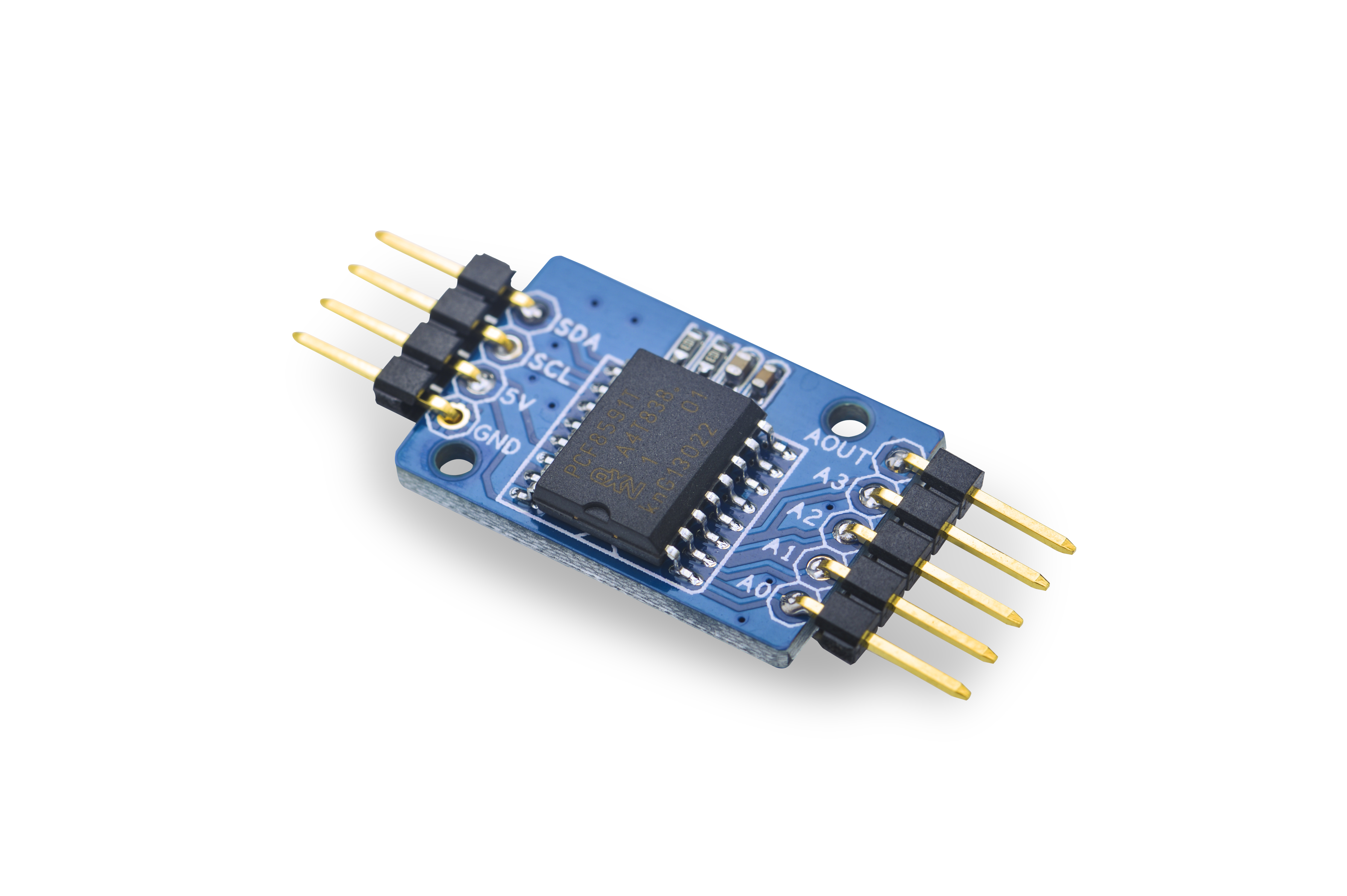
- The Matrix-Analog_to_Digital_Converter is a single-chip, single-supply low-power 8-bit CMOS data acquisition device.
- It utilizes the PCF8591 chip with four analog inputs, one analog output and a serial I2C-bus interface. Three address pins A0, A1 and A2 are used for programming the hardware address, allowing
the use of up to eight devices connected to the I2C-bus without additional hardware. Address, control and data to and from the device are transferred serially via the two-line bidirectional I2C-bus. The maximum conversion rate is given by the maximum speed of the I2C-bus.
- The I2C hardware address is configured to 1001000x
- The operating supply voltage is from 2.5V to 6.0V,Among the 2.54 mm spacing pin header the 5V pin is the supply voltage. If you need 0 - 3.3V analog signals and keep the acquisition resolution you can connect it to a 3.3V supply voltage.
2 Features
- Wide range supply voltage: 2.5V - 6.0V
- I2C interface: 3.3V/5V
- 8-bit A/D x 4
- 8-bit D/A x 1
- Small and easy to be used in various situations
- 2.54 mm spacing pin
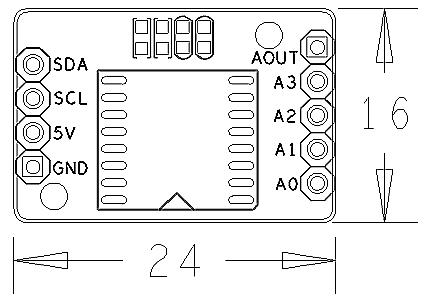
- PCB dimension (mm): 16 x 24
- Pin Description:
| Pin | Description |
| SDA | I2C SDA |
| SCL | I2C SCL |
| 5V | Supply Voltage 5V |
| GND | Ground |
| AOUT | Analog Output |
| A3 | Analog Input3 |
| A2 | Analog Input2 |
| A1 | Analog Input1 |
| A0 | Analog Input0 |
3 Basic Device Operation
The PCF8591's I2C-bus is for bidirectional, two-line communication between different ICs or modules. The two lines are a Serial DAta line (SDA) and a Serial CLock line (SCL). Both lines must
be connected to a positive supply via a pull-up resistor. Data transfer may be initiated only when the bus is not busy. The AINT0 - AINT4 pins are analog inputs which can be configured to single-ended or differential inputs. The supply voltage is 0 - VDD.
1. Each PCF8591 device in an I2C-bus system is activated by sending a valid address to the device. The address consists of a fixed part and a programmable part. The programmable part must be set according to the address pins A0, A1 and A2. The address is always sent as the first byte after the start condition in the I2C-bus protocol. The last bit of the address byte is the read/write-bit which sets the direction of the following data transfer.
2. The second byte sent to a PCF8591 device is stored in its control register and is required to control the device function. The upper nibble of the control register is used for enabling the analog output, and for programming the analog inputs as single-ended or differential inputs. The lower nibble selects one of the analog input channels defined by the upper nibble.
3. The on-chip D/A converter and a high-gain comparator are used temporarily during an A/D conversion cycle. An A/D conversion cycle is always started after sending a valid read mode address to a PCF8591 device. The A/D conversion cycle is triggered at the trailing edge of the acknowledge clock pulse and is executed while transmitting the result of the previous conversion。
4 Applications
4.1 Connect to NanoPi M1
Refer to the following connection diagram to connect the module to the NanoPi M1
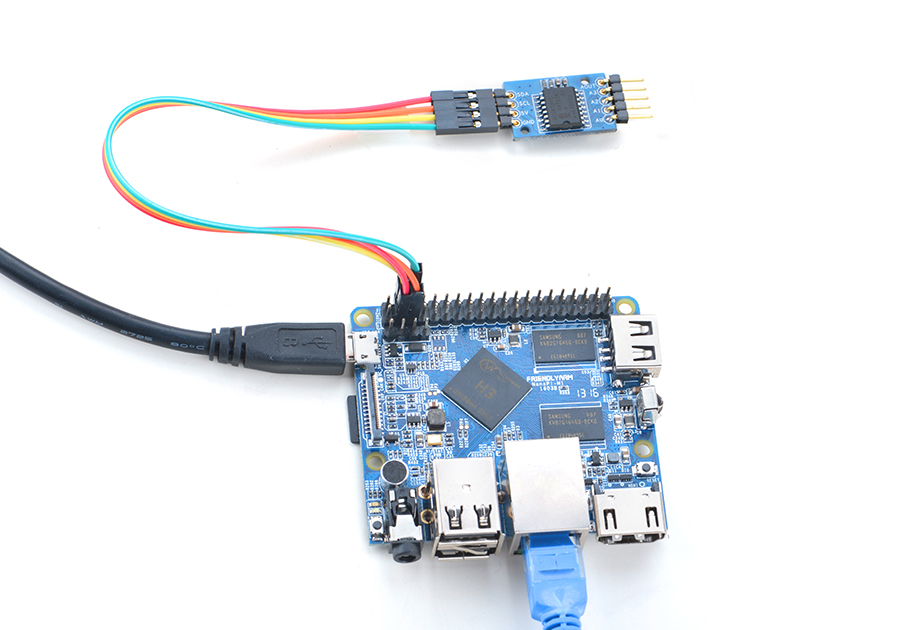
Connection Details:
| Matrix-Analog_to_Digital_Converter | NanoPi M1 |
| SDA | Pin3 |
| SCL | Pin5 |
| 5V | Pin4 |
| GND | Pin6 |
4.2 Connect to NanoPi 2
Refer to the following connection diagram to connect the module to the NanoPi 2:
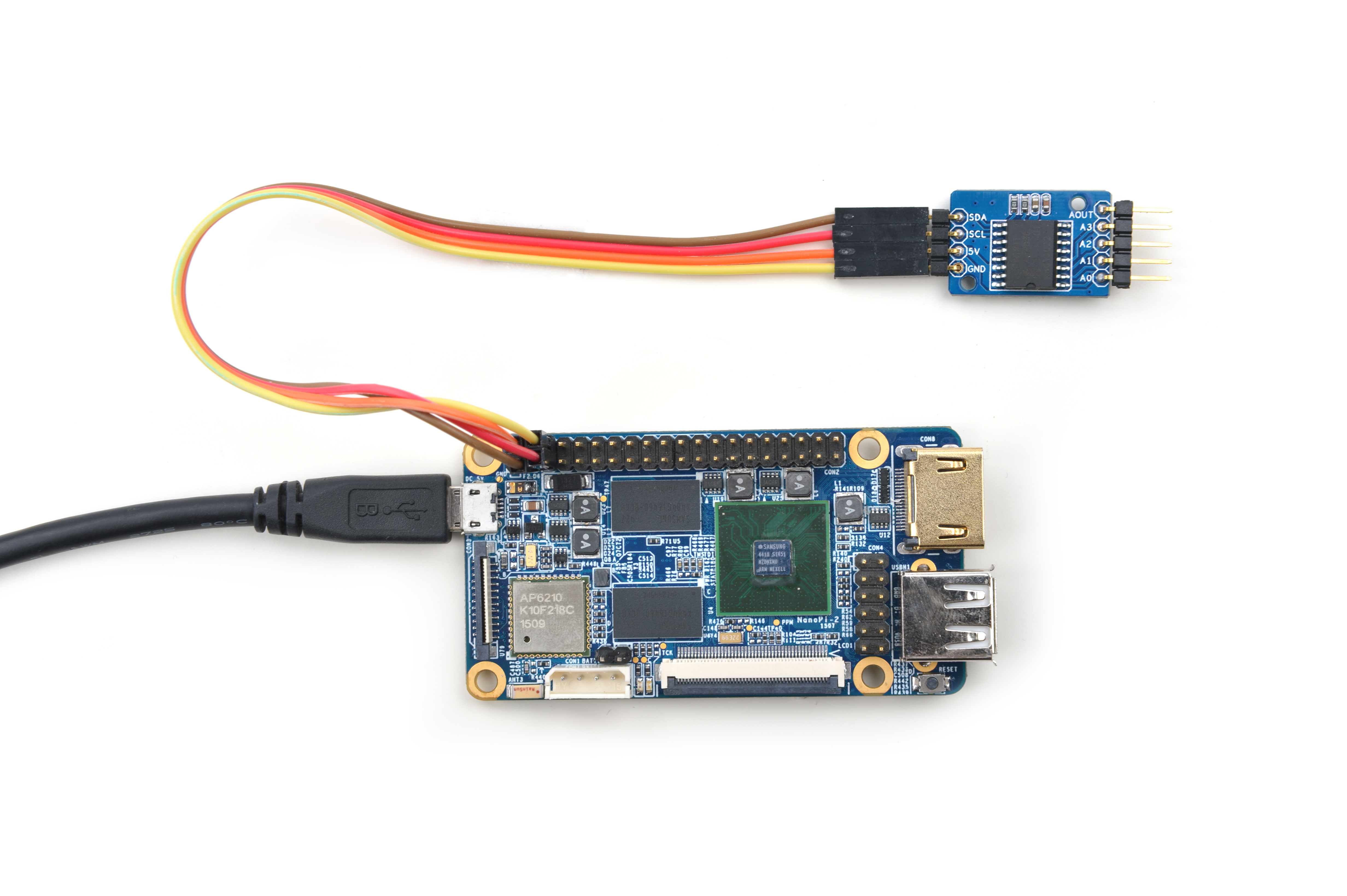
Connection Details:
| Matrix-Analog_to_Digital_Converter | NanoPi 2 |
| SDA | Pin3 |
| SCL | Pin5 |
| 5V | Pin4 |
| GND | Pin6 |
4.3 Connect to NanoPi M2 / NanoPi 2 Fire
Refer to the following connection diagram to connect the module to the NanoPi M2/ NanoPi 2 Fire:
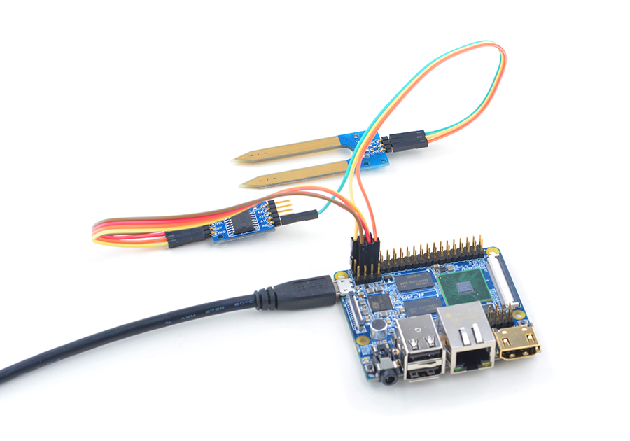
Connection Details:
| Matrix-Analog_to_Digital_Converter | NanoPi M2 |
| SDA | Pin3 |
| SCL | Pin5 |
| 5V | Pin4 |
| GND | Pin6 |
4.4 Connect to NanoPC-T2
Refer to the following connection diagram to connect the module to the NanoPC-T2
Matrix-Analog_to_Digital_Converter_NanoPC-T2
Connection Details:
| Matrix-Analog_to_Digital_Converter | NanoPC-T2 |
| SDA | Pin6 |
| SCL | Pin5 |
| 5V | Pin29 |
| GND | Pin30 |
5 Compile & Run Test Program
Boot your ARM board with Debian and copy the matrix code:
$ apt-get update && apt-get install git
$ git clone https://github.com/friendlyarm/matrix.git
If your cloning is done successfully a "matrix" directory will be generated.
Compile and install Matrix:
$ cd matrix
$ make && make install
Run test program:
$ matrix-adcNote: this module is not plug and play therefore before running the module please make sure it is connected to an ARM board.
Here is what you should observe:
The channel0 value is 2460When Channel 0 is connected to 5V its value reaches the maximum: 2550. When it is grounded its value is 0.
6 Code Sample
This Matrix code sample can work with all the ARM boards mentioned in this module's wiki. The name of this code sample is "matrix-analog_to_digital_converter". Here is its source code:
int main(int argc, char ** argv)
{
    int i = 0;
    int value = 0;
    int channel = 0;

    if (boardInit() < 0) {
        printf("Fail to init board\n");
        return -1;
    }

    if (argc == 2)
        channel = atoi(argv[1]);
    system("modprobe "DRIVER_MODULE);
    signal(SIGINT, intHandler);
    for (i=0; i<ADC_READ_TIMES; i++) {
        if (pcf8591Read(channel, &value) != -1) {
            printf("The channel%d value is %d\n", channel, value);
        } else {
            printf("Fail to get channel%d value\n", channel);
        }
    }
    system("rmmod "DRIVER_MODULE);

    return 0;
}
For more details about this APIs called in this code sample refer to Matrix API reference manual
7 Resources
8 Update Log
8.1 Feb-19-2016
- Added Section 5
8.2 June-17-2016
- Re-organized and simplified wiki
