Difference between revisions of "APITestPage"
(updated by API) |
(updated by API) |
||
| Line 1: | Line 1: | ||
| − | [[NanoPC-T2| | + | [[NanoPC-T2/zh|查看中文]] |
| − | == | + | |
| + | ==Introduction== | ||
[[File:NanoPC-T2-1B.jpg|thumb|Overview]] | [[File:NanoPC-T2-1B.jpg|thumb|Overview]] | ||
[[File:NanoPC-T2-A1.jpg|thumb|Front]] | [[File:NanoPC-T2-A1.jpg|thumb|Front]] | ||
[[File:NanoPC-T2-B1.jpg|thumb|Back]] | [[File:NanoPC-T2-B1.jpg|thumb|Back]] | ||
| − | * NanoPC- | + | * The NanoPC-T2 quad core Cortex A9 single board computer is designed and developed by FriendlyARM for professional and enterprise users. It uses the Samsung Quad Core Cortex-A9 S5P4418 SoC with dynamic frequency scaling up to 1.4GHz. Compared to FriendlyARM's existing 4418 based boards the NanoPC-T2 has 8G eMMC onboard, audio jack and video input/output interfaces. Compared to its predecessor the NanoPC-T1 the NanoPC-T2 has built-in WiFi, Bluetooth and Gbps Ethernet port. In addition the NanoPC-T2 has power management which the NanoPC-T1 doesn't support. To avoid overheat issues the NanoPC-T2 has a heat sink with mounting posts. |
| − | * | + | * The NanoPC-T2 combines all the ports and interfaces the existing FriendlyARM 4418 boards have. Currently it has the most interfaces and ports among all existing ARM boards of this size. Its rich video interfaces and support for HDMI 1080P enable it to work with not only popular display devices but also various FriendlyARM LCDs (both resistive touch and capacitive touch). |
| − | * | + | * The NanoPC-T2 is FriendlyARM's most complete solution based on Samsung 4418 for both commercial and industrial applications. |
| + | |||
| + | ==Hardware Spec== | ||
| + | * SoC: Samsung S5P4418 Quad Core Cortex-A9 with dynamic frequency scaling up to 1.4G Hz | ||
| + | * Power Management Unit: AXP228 PMU, it supports software power-off and wake-up. | ||
| + | * System Memory: 1GB 32bit DDR3 RAM | ||
| + | * eMMC: 8GB | ||
| + | * Storage: 1 x SD Card Slot | ||
| + | * Ethernet: Gbps Ethernet Port (RTL8211E) with unique MAC | ||
| + | * WiFi: 802.11b/g/n | ||
| + | * Bluetooth: 4.0 dual mode | ||
| + | * Antenna: Porcelain Antenna IPX Interface | ||
| + | * Video Input: DVP Camera/MIPI-CSI (two camera interfaces) | ||
| + | * Video Output: HDMI Type-A / LVDS / LCD / MIPI DSI (four video output interfaces) | ||
| + | * Audio: 3.5 mm audio jack / via HDMI | ||
| + | * Microphone: 1 x onboard Microphone | ||
| + | * USB: 4 x USB 2.0 Host, two standard type A ports and two 2.54mm pitch pin headers | ||
| + | * MicroUSB: 1 x MicroUSB 2.0 Client, Type A | ||
| + | * LCD Interface: 0.5mm pitch 45 pin FPC seat, full color RGB 8-8-8 | ||
| + | * HDMI: 1.4A Type A, 1080P | ||
| + | * DVP Camera: 0.5mm pitch 24 pin FPC seat | ||
| + | * GPIO: 2.54 mm pitch 30 pin header | ||
| + | * Serial Debug Port: 2.54mm pitch 4pin header | ||
| + | * LED: 1 x power LED , 2 x GPIO LED | ||
| + | * User Key: 1 x K1 (power), 1 x Reset | ||
| + | * Other Resource: 1 x onboard thermistor | ||
| + | * RTC Battery: RTC Seat Pins | ||
| + | * Power: DC 5V/2A | ||
| + | * Heat Sink: 1 x Heat Sink with mounting holes | ||
| + | * PCB: Six Layer, ENIG | ||
| + | * PCB Dimension: 100 mm x 60 mm | ||
| + | * Working Temperature: -40℃ to 70℃ | ||
| + | * OS/Software: u-boot, Android 4.4, Android5.1 and Debian8 | ||
| + | |||
| + | ==Software Features== | ||
| + | ===UbuntuCore=== | ||
| + | <!--- | ||
| + | * mainline kernel: Linux-4.11.2 | ||
| + | * rpi-monitor: check system status and information | ||
| + | ---> | ||
| + | * npi-config: system configuration utility for setting passwords, language, timezone, hostname, SSH and auto-login,and enabling/disabling i2c, spi, serial and PWM | ||
| + | <!--- | ||
| + | * software utility: wiringNP to access GPIO pins | ||
| + | * software utility: RPi.GPIO_NP to access GPIO pins | ||
| + | ---> | ||
| + | * networkmanager: manage network | ||
| + | * system log output from serial port | ||
| + | <!--- | ||
| + | * nano editor | ||
| + | ---> | ||
| + | * welcome window with basic system information and status | ||
| + | * auto-login with user account "pi" with access to npi-config | ||
| + | * UART2 enabled | ||
| + | * supports CAM500B | ||
| + | <!--- | ||
| + | * sudoers include "fa" | ||
| + | * on first system boot file system will be automatically extended. | ||
| + | * supports file system auto check and repair on system boot. | ||
| + | * supports FriendlyElec's [http://wiki.friendlyarm.com/wiki/index.php/NanoHat_PCM5102A NanoHat-PCM5102A] | ||
| + | * supports USB WiFi module: refer to [[#Connect USB WiFi to NEO]] | ||
| + | * supports audio recording and playing with 3.5mm audio jack | ||
| + | * supports USB Host and 100M Ethernet | ||
| + | * supports FriendlyElec BakeBit modules | ||
| + | * supports dynamic frequency scaling and voltage regulation | ||
| + | * relieves overheat compared to kernel Linux-3.4 | ||
| + | * fixed MAC address | ||
| + | |||
| + | ===Ubuntu OLED=== | ||
| + | * mainline kernel: Linux-4.11.2 | ||
| + | * supports FriendlyElec's OLED module | ||
| + | ---> | ||
| + | |||
| + | ===Debian=== | ||
| + | * supports CAM500B | ||
| − | == | + | <!--- |
| − | * | + | ===Debian for NAS Dock=== |
| − | + | * mainline kernel: Linux-4.11.2 | |
| − | + | * supports FriendlyElec's NAS Dock | |
| − | + | * optimized OpenMediaVault configuration options | |
| − | + | * allocated swap section | |
| − | + | ---> | |
| − | + | ===Android=== | |
| − | * | + | * supports setting up static IP |
| − | * | + | * supports accessing hardware with FriendlyElec's libfriendlyarm-hardware.so |
| − | * | + | * integrated iTest utility for testing hardware |
| − | + | ||
| − | + | ||
| − | * | + | |
| − | * | + | |
| − | + | ||
| − | + | ||
| − | + | ||
| − | * | + | |
| − | + | ||
| − | + | ||
| − | + | ||
| − | + | ||
| − | + | ||
| − | + | ||
| − | + | ||
| − | + | ||
| − | + | ||
| − | + | ||
| − | + | ||
| − | == | + | ==Diagram, Layout and Dimension== |
| − | === | + | ===Layout=== |
| − | [[File:NanoPC-T2-IF.png |thumb|600px|NanoPC- | + | [[File:NanoPC-T2-IF.png |thumb|600px|NanoPC-T2 Layout]] |
| − | * '''30Pin | + | * '''30Pin GPIO Pin Spec''' |
::{| class="wikitable" | ::{| class="wikitable" | ||
|- | |- | ||
| Line 79: | Line 134: | ||
|} | |} | ||
| − | * '''20Pin | + | * '''20Pin LVDS Interface Pin Spec''' |
::{| class="wikitable" | ::{| class="wikitable" | ||
|- | |- | ||
| Line 105: | Line 160: | ||
|} | |} | ||
| − | * '''DVP | + | * '''DVP Camera Interface Pin Spec''' |
::{| class="wikitable" | ::{| class="wikitable" | ||
|- | |- | ||
| Line 133: | Line 188: | ||
|} | |} | ||
| − | * '''RGB LCD IF | + | * '''RGB LCD IF Pin Spec''' |
::{| class="wikitable" | ::{| class="wikitable" | ||
|- | |- | ||
|Pin# || Name || Description | |Pin# || Name || Description | ||
|- | |- | ||
| − | |1, 2 || VDD_5V || | + | |1, 2 || VDD_5V || 5V Output, it can be used to power LCD modules |
|- | |- | ||
| − | |11,20,29, 37,38,39,40, 45|| DGND || | + | |11,20,29, 37,38,39,40, 45|| DGND || Ground |
|- | |- | ||
| − | |3-10 || Blue LSB to MSB || | + | |3-10 || Blue LSB to MSB || RGB blue |
|- | |- | ||
| − | |12-19 || Green LSB to MSB || | + | |12-19 || Green LSB to MSB || RGB green |
|- | |- | ||
| − | |21-28 || Red LSB to MSB || | + | |21-28 || Red LSB to MSB || RGB red |
|- | |- | ||
| − | |30 || GPIOB25 || | + | |30 || GPIOB25 || available for users |
|- | |- | ||
| − | |31 || GPIOC15 || | + | |31 || GPIOC15 || occupied by FriendlyARM one wire technology to recognize LCD models and control backlight and implement resistive touch, not applicable for users |
| − | + | ||
|- | |- | ||
| − | |32 || XnRSTOUT Form CPU || | + | |32 || XnRSTOUT Form CPU || low when system is reset |
|- | |- | ||
| − | |33 || VDEN || | + | |33 || VDEN || signal the external LCD that data is valid on the data bus |
|- | |- | ||
| − | |34 || VSYNC || | + | |34 || VSYNC || vertical synchronization |
|- | |- | ||
| − | |35 || HSYNC || | + | |35 || HSYNC || horizontal synchronization |
|- | |- | ||
| − | |36 || LCDCLK || | + | |36 || LCDCLK || LCD clock, Pixel frequency |
|- | |- | ||
| − | |41 || I2C2_SCL || | + | |41 || I2C2_SCL || I2C2 clock signal, for capacitive touch data transmission |
|- | |- | ||
| − | |42 || I2C2_SDA || | + | |42 || I2C2_SDA || I2C2 data signal, for capacitive touch data transmission |
|- | |- | ||
| − | |43 || GPIOC16 || | + | |43 || GPIOC16 || interrupt pin for capacitive touch, used with I2C2 |
|- | |- | ||
| − | |44 || NC || | + | |44 || NC || Not connected |
|} | |} | ||
| − | * '''MIPI- | + | * '''MIPI-DSI Interface Pin Spec''' |
::{| class="wikitable" | ::{| class="wikitable" | ||
|- | |- | ||
| Line 232: | Line 286: | ||
|} | |} | ||
| − | * '''MIPI- | + | * '''MIPI-CSI Interface Pin Spec''' |
::{| class="wikitable" | ::{| class="wikitable" | ||
|- | |- | ||
| Line 293: | Line 347: | ||
|30 || DGND | |30 || DGND | ||
|} | |} | ||
| − | :''' | + | :'''Note:''' |
| − | ::#SYS_3.3V: 3. | + | ::#SYS_3.3V: 3.3V power output |
| − | ::#VDD_5V: | + | ::#VDD_5V: 5V power output |
| − | ::# | + | ::#For more details refer to the document: [http://wiki.friendlyarm.com/wiki/images/0/00/NanoPC-T2_1601B_Schematic.pdf NanoPC-T2_1601B_Schematic.pdf] |
| − | === | + | ===Board Dimension=== |
[[File:NanoPC-T2-T3-1603-Dimensions.png|frameless|800px|NanoPC-T2 Dimensions]] | [[File:NanoPC-T2-T3-1603-Dimensions.png|frameless|800px|NanoPC-T2 Dimensions]] | ||
| − | :: | + | ::For more details refer to the document: [http://wiki.friendlyarm.com/wiki/images/2/24/NanoPC-T2-T3-1603-Dimensions%28dxf%29.zip NanoPC-T2-Dimensions(dxf)] |
| − | *''' | + | *'''Power Jack''' |
| − | ::* | + | ::*DC 4.7~5.6V IN, 4.0*1.7mm Power Jack |
::[[File:DC-023.png]] | ::[[File:DC-023.png]] | ||
| − | == | + | ==Notes in Hardware Design== |
===EEPROM=== | ===EEPROM=== | ||
| − | * | + | * The board has an EEPROM(model: 24AA025E48T-I/OT) with a unique MAC. This EEPROM is connected to I2C0 and its address is 0x51 therefore some EEPROM chips cannot be connected to I2C0 which will cause conflicts of addresses. |
| − | * | + | * In our tests these EEPROM chips cannot be connected to I2C0: 24C04, 24C08 and 24C16. There chips which we tested can be connected to I2C0: 24C01, 24C02 and 24C256 |
| − | * | + | * For more details about EEPROM address issues refer to http://www.onsemi.com/pub_link/Collateral/CAT24C01-D.PDF |
| − | == | + | ==Get Started== |
| − | === | + | ===Essentials You Need=== |
| − | + | Before starting to use your NanoPC-T2 get the following items ready | |
| − | * NanoPC- | + | * NanoPC-T2 |
| − | * | + | * SD Card: Class 10 or Above, minimum 8GB SDHC |
| − | * | + | * A DC 5V/2A power is a must |
| − | * | + | * HDMI monitor or LCD |
| − | * | + | * USB keyboard, mouse and possible a USB hub(or a TTL to serial board) |
| − | * | + | * A host computer running Ubuntu 16.04 64 bit system |
| − | {{S5P4418BootFromSDCard | + | {{S5P4418BootFromSDCard|NanoPi-T2}} |
| − | {{BurnOSToEMMC | + | {{BurnOSToEMMC|NanoPC-T2|s5p4418-eflasher}} |
| − | {{S5PXX18MakeSDCardViaSDFusing | + | {{S5PXX18MakeSDCardViaSDFusing|NanoPC-T2|sd-fuse_nanopi2}} |
| − | {{ResizeTFCardFS | + | {{ResizeTFCardFS|NanoPC-T2}} |
| − | {{S5Pxx18HDMI | + | {{S5Pxx18HDMI|NanoPC-T2|arch/arm/plat-s5p4418/nanopi2/lcds.c}} |
| − | {{S5Pxx18MofidyKernelCommandLineOnHostPC | + | {{S5Pxx18MofidyKernelCommandLineOnHostPC|NanoPC-T2|sd-fuse_nanopi2}} |
| − | {{S5P4418Software | + | {{NanoPCStartToUse|NanoPC-T2}} |
| − | {{S5P4418ChangeLog | + | {{S5P4418Software|NanoPi-T2}} |
| + | {{S5P4418ChangeLog}} | ||
Revision as of 02:41, 20 December 2017
Contents
- 1 Introduction
- 2 Hardware Spec
- 3 Software Features
- 4 Diagram, Layout and Dimension
- 5 Notes in Hardware Design
- 6 Get Started
- 7 Update Log
- 7.1 2023-01-09
- 7.2 2020-10-26
- 7.3 2019-12-28
- 7.4 2019-11-26
- 7.5 2019-11-14
- 7.6 2019-10-18
- 7.7 2019-09-30
- 7.8 2019-07-18
- 7.9 2019-06-25
- 7.10 2019-06-03
- 7.11 2019-01-24
- 7.12 2018-12-17
- 7.13 March-04-2016
- 7.14 March-09-2016
- 7.15 March-23-2016
- 7.16 March-27-2016
- 7.17 April-08-2016
- 7.18 June-30-2016
- 7.19 Sep-04-2016
- 7.20 Sep-27-2016
- 7.21 Nov-2-2016
- 7.22 Nov-17-2016
- 7.23 Dec-7-2016
- 7.24 June-13-2016
- 7.25 June-20-2016
1 Introduction


- The NanoPC-T2 quad core Cortex A9 single board computer is designed and developed by FriendlyARM for professional and enterprise users. It uses the Samsung Quad Core Cortex-A9 S5P4418 SoC with dynamic frequency scaling up to 1.4GHz. Compared to FriendlyARM's existing 4418 based boards the NanoPC-T2 has 8G eMMC onboard, audio jack and video input/output interfaces. Compared to its predecessor the NanoPC-T1 the NanoPC-T2 has built-in WiFi, Bluetooth and Gbps Ethernet port. In addition the NanoPC-T2 has power management which the NanoPC-T1 doesn't support. To avoid overheat issues the NanoPC-T2 has a heat sink with mounting posts.
- The NanoPC-T2 combines all the ports and interfaces the existing FriendlyARM 4418 boards have. Currently it has the most interfaces and ports among all existing ARM boards of this size. Its rich video interfaces and support for HDMI 1080P enable it to work with not only popular display devices but also various FriendlyARM LCDs (both resistive touch and capacitive touch).
- The NanoPC-T2 is FriendlyARM's most complete solution based on Samsung 4418 for both commercial and industrial applications.
2 Hardware Spec
- SoC: Samsung S5P4418 Quad Core Cortex-A9 with dynamic frequency scaling up to 1.4G Hz
- Power Management Unit: AXP228 PMU, it supports software power-off and wake-up.
- System Memory: 1GB 32bit DDR3 RAM
- eMMC: 8GB
- Storage: 1 x SD Card Slot
- Ethernet: Gbps Ethernet Port (RTL8211E) with unique MAC
- WiFi: 802.11b/g/n
- Bluetooth: 4.0 dual mode
- Antenna: Porcelain Antenna IPX Interface
- Video Input: DVP Camera/MIPI-CSI (two camera interfaces)
- Video Output: HDMI Type-A / LVDS / LCD / MIPI DSI (four video output interfaces)
- Audio: 3.5 mm audio jack / via HDMI
- Microphone: 1 x onboard Microphone
- USB: 4 x USB 2.0 Host, two standard type A ports and two 2.54mm pitch pin headers
- MicroUSB: 1 x MicroUSB 2.0 Client, Type A
- LCD Interface: 0.5mm pitch 45 pin FPC seat, full color RGB 8-8-8
- HDMI: 1.4A Type A, 1080P
- DVP Camera: 0.5mm pitch 24 pin FPC seat
- GPIO: 2.54 mm pitch 30 pin header
- Serial Debug Port: 2.54mm pitch 4pin header
- LED: 1 x power LED , 2 x GPIO LED
- User Key: 1 x K1 (power), 1 x Reset
- Other Resource: 1 x onboard thermistor
- RTC Battery: RTC Seat Pins
- Power: DC 5V/2A
- Heat Sink: 1 x Heat Sink with mounting holes
- PCB: Six Layer, ENIG
- PCB Dimension: 100 mm x 60 mm
- Working Temperature: -40℃ to 70℃
- OS/Software: u-boot, Android 4.4, Android5.1 and Debian8
3 Software Features
3.1 UbuntuCore
- npi-config: system configuration utility for setting passwords, language, timezone, hostname, SSH and auto-login,and enabling/disabling i2c, spi, serial and PWM
- networkmanager: manage network
- system log output from serial port
- welcome window with basic system information and status
- auto-login with user account "pi" with access to npi-config
- UART2 enabled
- supports CAM500B
3.2 Debian
- supports CAM500B
3.3 Android
- supports setting up static IP
- supports accessing hardware with FriendlyElec's libfriendlyarm-hardware.so
- integrated iTest utility for testing hardware
4 Diagram, Layout and Dimension
4.1 Layout

- 30Pin GPIO Pin Spec
Pin# Name Pin# Name 1 SYS_3.3V 2 DGND 3 UART2_TX/GPIOD20 4 UART2_RX/GPIOD16 5 I2C0_SCL 6 I2C0_SDA 7 SPI0_MOSI/GPIOC31 8 SPI0_MISO/GPIOD0 9 SPI0_CLK/GPIOC29 10 SPI0_CS/GPIOC30 11 UART3_TX/GPIOD21 12 UART3_RX/GPIOD17 13 UART4_TX/GPIOB29 14 UART4_RX/GPIOB28 15 GPIOB31 16 GPIOB30 17 GPIOC4 18 GPIOC7 19 GPIOC8 20 GPIOC24 21 GPIOC28 22 GPIOB26 23 GPIOD1/PWM0 24 GPIOD8/PPM 25 GPIOC13/PWM1 26 AliveGPIO3 27 GPIOC14/PWM2 28 AliveGPIO5 29 VDD_5V 30 DGND
- 20Pin LVDS Interface Pin Spec
Pin# Name Pin# Name 1 SYS_3.3V 2 SYS_3.3V 3 GPIOC16 4 GPIOB18 5 DGND 6 DGND 7 LVDS_D0- 8 LVDS_D0+ 9 LVDS_D1- 10 LVDS_D1+ 11 LVDS_D2- 12 LVDS_D2+ 13 DGND 14 DGND 15 LVDS_CLK- 16 LVDS_CLK+ 17 LVDS_D3- 18 LVDS_D3+ 19 I2C2_SCL 20 I2C2_SDA
- DVP Camera Interface Pin Spec
Pin# Name 1, 2 SYS_3.3V 7,9,13,15,24 DGND 3 I2C0_SCL 4 I2C0_SDA 5 GPIOB14 6 GPIOB16 8,10 NC 11 VSYNC 12 HREF 14 PCLK 16-23 Data bit7-0
- RGB LCD IF Pin Spec
Pin# Name Description 1, 2 VDD_5V 5V Output, it can be used to power LCD modules 11,20,29, 37,38,39,40, 45 DGND Ground 3-10 Blue LSB to MSB RGB blue 12-19 Green LSB to MSB RGB green 21-28 Red LSB to MSB RGB red 30 GPIOB25 available for users 31 GPIOC15 occupied by FriendlyARM one wire technology to recognize LCD models and control backlight and implement resistive touch, not applicable for users 32 XnRSTOUT Form CPU low when system is reset 33 VDEN signal the external LCD that data is valid on the data bus 34 VSYNC vertical synchronization 35 HSYNC horizontal synchronization 36 LCDCLK LCD clock, Pixel frequency 41 I2C2_SCL I2C2 clock signal, for capacitive touch data transmission 42 I2C2_SDA I2C2 data signal, for capacitive touch data transmission 43 GPIOC16 interrupt pin for capacitive touch, used with I2C2 44 NC Not connected
- MIPI-DSI Interface Pin Spec
Pin# Name 1, 2, 3 VDD_5V 4 DGND 5 I2C2_SDA 6 I2C2_SCL 7 DGND 8 GPIOC0 9 DGND 10 GPIOC1 11 DGND 12 GPIOA28 13 nRESETOUT 14, 15 DGND 16 MIPIDSI_DN3 17 MIPIDSI_DP3 18 DGND 19 MIPIDSI_DN2 20 MIPIDSI_DP2 21 DGND 22 MIPIDSI_DN1 23 MIPIDSI_DP1 24 DGND 25 MIPIDSI_DN0 26 MIPIDSI_DP0 27 DGND 28 MIPIDSI_DNCLK 29 MIPIDSI_DPCLK 30 DGND
- MIPI-CSI Interface Pin Spec
Pin# Name 1, 2 SYS_3.3V 3 DGND 4 I2C0_SDA 5 I2C0_SCL 6 DGND 7 SPI2_MOSI/GPIOC12 8 SPI2_MISO/GPIOC11 9 SPI2_CS/GPIOC10 10 SPI2_CLK/GPIOC9 11 DGND 12 GPIOB9 13 GPIOC2 14, 15 DGND 16 MIPICSI_DN3 17 MIPICSI_DP3 18 DGND 19 MIPICSI_DN2 20 MIPICSI_DP2 21 DGND 22 MIPICSI_DN1 23 MIPICSI_DP1 24 DGND 25 MIPICSI_DN0 26 MIPICSI_DP0 27 DGND 28 MIPICSI_DNCLK 29 MIPICSI_DPCLK 30 DGND
- Note:
- SYS_3.3V: 3.3V power output
- VDD_5V: 5V power output
- For more details refer to the document: NanoPC-T2_1601B_Schematic.pdf
4.2 Board Dimension

- For more details refer to the document: NanoPC-T2-Dimensions(dxf)
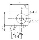
- Power Jack
- DC 4.7~5.6V IN, 4.0*1.7mm Power Jack

5 Notes in Hardware Design
5.1 EEPROM
- The board has an EEPROM(model: 24AA025E48T-I/OT) with a unique MAC. This EEPROM is connected to I2C0 and its address is 0x51 therefore some EEPROM chips cannot be connected to I2C0 which will cause conflicts of addresses.
- In our tests these EEPROM chips cannot be connected to I2C0: 24C04, 24C08 and 24C16. There chips which we tested can be connected to I2C0: 24C01, 24C02 and 24C256
- For more details about EEPROM address issues refer to http://www.onsemi.com/pub_link/Collateral/CAT24C01-D.PDF
6 Get Started
6.1 Essentials You Need
Before starting to use your NanoPC-T2 get the following items ready
- NanoPC-T2
- SD Card: Class 10 or Above, minimum 8GB SDHC
- A DC 5V/2A power is a must
- HDMI monitor or LCD
- USB keyboard, mouse and possible a USB hub(or a TTL to serial board)
- A host computer running Ubuntu 16.04 64 bit system
6.2 Boot from SD Card
Get the following files from here download link:
- Get a 8G SDHC card and backup its data if necessary.
| Image Files | |
| s5p4418-sd-friendlycore-xenial-4.4-armhf-YYYYMMDD.img.zip | FriendlyCore with Qt 5.10.0 (base on Ubuntu core) image file |
| s5p4418-sd-lubuntu-desktop-xenial-4.4-armhf-YYYYMMDD.img.zip | LUbuntu Desktop image file with X Window |
| s5p4418-sd-friendlywrt-4.4-YYYYMMDD.img.zip | FriendlyWrt image file (base on OpenWrt) |
| s5p4418-sd-android7-YYYYMMDD.img.zip | Android7 image file |
| s5p4418-sd-android-kitkat-YYYYMMDD.img.zip | Android4.4 image file with support for 4G LTE |
| s5p4418-sd-android-lollipop-YYYYMMDD.img.zip | Android5.1 image file |
| s5p4418-eflasher-lubuntu-desktop-xenial-4.4-armhf-YYYYMMDD.img.zip | SD card image, which is used to install a lubuntu desktop to eMMC |
| s5p4418-eflasher-friendlywrt-4.4-YYYYMMDD.img.zip | SD card image, which is used to install a FriendlyWrt to eMMC |
| s5p4418-eflasher-android7-YYYYMMDD.img.zip | SD card image, which is used to install a android7 to eMMC |
| s5p4418-eflasher-friendlycore-xenial-4.4-armhf-YYYYMMDD.img.zip | SD card image, which is used to install a friendly-core to eMMC |
| s5p4418-eflasher-android-kitkat-YYYYMMDD.img.zip | SD card image, which is used to install a android4 to eMMC |
| s5p4418-eflasher-android-lollipop-YYYYMMDD.img.zip | SD card image, which is used to install a android5 to eMMC |
| Flash Utility: | |
| win32diskimager.rar | Windows utility. Under Linux users can use "dd" |
- Uncompress these files. Insert an SD card(at least 4G) into a Windows PC and run the win32diskimager utility as administrator. On the utility's main window select your SD card's drive, the wanted image file and click on "write" to start flashing the SD card.
- Insert this card into your board's boot slot, press and hold the boot key (only applies to a board with onboard eMMC) and power on (with a 5V/2A power source). If the PWR LED is on and LED1 is blinking this indicates your board has successfully booted.
6.3 Flash image to eMMC with eflasher
- Download eflasher image file
An image file's name is as : s5p4418-eflasher-OSNAME-YYYYMMDD.img.zip
The "OSNAME" is the name of an OS e.g. android, friendlycore and etc;
This image file is used for making an installation SD card and it contains a Ubuntu core system and a utility EFlasher;
Download s5p4418-eflasher-OSNAME-YYYYMMDD.img.zip to a host PC and get a windows utility win32diskimager.rar as well;
- Make Installation SD Card with eflasher
Extract the package with a 7z utility and you will get a file with an extension ".img". Insert an SDHC card(minimum 8G or above) to a PC running Windows, run the Win32DiskImager utility as administrator, click on "Image File" to select your wanted file, select your SD card and click on "Write" to start flashing the Image to your SD card;
If your PC runs Linux you can command "dd" to extract the package and get an ".img" file and write it to your SD card;
- Operate in GUI Window: Flash OS to eMMC
Insert your SD card to NanoPC-T2, connect an HDMI monitor or LCD to your board, press and hold the "boot" key beside the Ethernet port, power on the board you will see a pop-up window asking you to select an OS for installation. Select your wanted OS and start installation.
- Operate in Commandline Utility: Flash OS to eMMC
Insert an installation SD card to NanoPC-T2, log into or SSH to your board and run the following command to start EFlasher:
sudo eflasher6.3.1 Make Installation Card under Linux Desktop
- 1) Insert your SD card into a host computer running Ubuntu and check your SD card's device name
dmesg | tail
Search the messages output by "dmesg" for similar words like "sdc: sdc1 sdc2". If you can find them it means your SD card has been recognized as "/dev/sdc". Or you can check that by commanding "cat /proc/partitions"
- 2) Downlaod Linux script
git clone https://github.com/friendlyarm/sd-fuse_nanopi2.git
cd sd-fuse_nanopi2
- 3) Here is how to make a Lubuntu desktop SD card
sudo ./fusing.sh /dev/sdx lubuntu
(Note: you need to replace "/dev/sdx" with the device name in your system)
When you run the script for the first time it will prompt you to download an image you have to hit “Y” within 10 seconds otherwise you will miss the download
- 4) Run this command to make a complete image file:
sudo ./mkimage.sh lubuntu
More content please refre: Assembling the SD card image yourself
6.4 Extend SD Card Section
- When Debian/Ubuntu is loaded the SD card's section will be automatically extended.
- When Android is loaded you need to run the following commands on your host PC to extend your SD card's section:
sudo umount /dev/sdx?
sudo parted /dev/sdx unit % resizepart 4 100 resizepart 7 100 unit MB print
sudo resize2fs -f /dev/sdx7
(Note: you need to replace "/dev/sdx" with the device name in your system)
6.5 LCD/HDMI Resolution
When the system boots our uboot will check whether it is connected to an LCD or to an HDMI monitor. If it recognizes an LCD it will configure its resolution. Our uboot defaults to the HDMI 720P configuration.
If you want to modify the LCD resolution you can modify file "arch/arm/plat-s5p4418/nanopi2/lcds.c" in the kernel and recompile it.
If your NanoPC-T2 is connected to an HDMI monitor and it runs Android it will automatically set the resolution to an appropriate HDMI mode by checking the "EDID". If your NanoPC-T2 is connected to an HDMI monitor and it runs Debian by default it will set the resolution to the HDMI 720P configuration. If you want to modify the HDMI resolution to 1080P modify your kernel's configuration as explained above.
6.6 Update SD Card's boot parameters From PC Host
Insert your SD card into a host PC running Linux, if you want to change your kernel command line parameters you can do it via the fw_setevn utility.
Check the current Command Line:
git clone https://github.com/friendlyarm/sd-fuse_nanopi2.git
cd sd-fuse_nanopi2/tools
./fw_printenv /dev/sdx | grep bootargs
For example, to disable android SELinux, You can change it this way:
./fw_setenv /dev/sdc bootargs XXX androidboot.selinux=permissive
The "XXX" stands for the original bootargs' value.
6.7 Run Android or Linux (TODO)
- 将制作好SD卡插入NanoPC-T2,连接HDMI,按住靠近网口的boot按键,最后接电源(5V 2A)拨动开关,NanoPC-T2会从SD卡启动。你可以看到板上PWR灯常亮,LED1灯闪烁,这说明系统已经开始启动了,同时电视上也将能看到系统启动的画面。
- 要在电视上进行操作,你需要连接USB鼠标和键盘;如果你选购了LCD配件,则可以直接使用LCD上面的触摸屏进行操作。
7 Update Log
7.1 2023-01-09
7.1.1 FriendlyCore:
- optimized the systemd service
7.2 2020-10-26
- FriendlyCore, Lubuntu:
Fix Bluetooth stability issue
7.3 2019-12-28
- eflasher:
1) Supports flashing only some files, such as updating only the kernel and uboot in emmc
2) Added gui option to disable overlay filesystem
3) Add command line parameters to achieve one-click installation without interaction
4) Fix the issue that the same mac address will appear on different devices after backup and restore image
5) UI interface can now be configured with title, hide interface menus and buttons
7.4 2019-11-26
- FriendlyCore:
Pre-installed OpenCV 4.1.2
7.5 2019-11-14
- Introducing a new system FriendlyWrt:
FriendlyWrt is a customized OpenWrt system developed by FriendlyElec. It is open source and suitable for applications in IoT, NAS etc.
Please refre: http://wiki.friendlyelec.com/wiki/index.php/How_to_Build_FriendlyWrt
- FriendlyCore, Lubuntu updated as follows:
1) Added support for new 4.3-inch screen YZ43
2) Compile bcmdhd as a module.
- Android7 update is as follows:
1) Added support for new 4.3-inch screen YZ43
2) Optimize the touch experience when using HD900 screen under Android 7 system
3) Optimize the touch experience when using S702 screen under Android 7 system
7.6 2019-10-18
- Android7, FriendlyCore, Lubuntu:
Fixed audio playback issue.
7.7 2019-09-30
- Android7 updated as follows:
1)Added support for Android hardware access library (named FriendlyThing), support access to hardware resources such as GPIO, PWM, RTC, serial port and watchdog, providing open source demo
2) Added support for camera CAM500B (OV5640)
3) Added support for LCD W500 (800x480)
4) Fixed LCD-S430 compatibility issues
- FriendlyCore, FriendlyDesktop updated as follows:
1) Kernel version updated to v4.4.172, same as Android 7
2) Added Docker support, support 32bit and 64bit file systems
3) Kernel configuration items are optimized to enable more features and device drivers
7.8 2019-07-18
- Introducing a new system Android 7.1.2
1) Features similar to the old version of Android 5, support 4G, WiFi, Ethernet, Bluetooth, etc.
2) Kernel version: 4.4.172
3) Known issue: The camera is not working yet
- Android/FriendlyCore/Lubuntu updated as follows:
1) Fix an issue where HD101B can't be touched in some cases
2) Fix GPIO configuration of Power key
3) Solve the problem of too small volume: the volume of the DAC is changed from -20dB to -6dB during playback.
4) Add more models of USB Wi-Fi support, built-in driver rtl8821CU.ko, rtl88XXau.ko
- Updates for Lubuntu only:
1) Modify Lubuntu's Power key behavior to (without pop-ups) shut down directly
2) Add script xrotate.sh to simplify screen rotation settings (Note: screen rotation will lose performance)
- The following updates are only available for NanoPC T2, Smart4418:
Support for reading Ethernet Mac addresses from the onboard EEPROM, only supports the following systems: FriendlyCore, Lubuntu, Android7
7.9 2019-06-25
Linux(Ubuntu 16.04/18.04) uses OverlayFS to enhance filesystem stability.
7.10 2019-06-03
1) Configure LED1 to be in heartbeat mode
2) Fix HDMI 1080P may have no display problem in some cases
3) Fix the issue that mysql cannot be installed under Linux
4) Fix the issue that the 1-wire touch resistance screen cannot be used under lubuntu
7.11 2019-01-24
1) Update uboot-v2014.07, uboot-v2016.01 for HD702V LCD
2) Adjust Qt5 font path
7.12 2018-12-17
- Android5 updated as follows:
1) Add support for 4G network, support module: Quectel EC20
2) Add audio setting UI, you can set the default output to headphones or HDMI
3) Synchronously turn off the backlight of the one-line touch screen when the system Shutdown
- FriendlyCore updated as follows:
1) Add OV5640 camera support
2) Update BL1 to improve system startup stability
- Lubuntu updated as follows:
1) Add Chrome-browser browser, support web page 1080P hardware decoding, support WebGL
2) Set the audio output channel to HDMI by default (can be changed via /etc/asound.conf)
3) Update BL1 to improve system startup stability
4) Fixed some issues regarding the package error in the previous version
5) Adjust DPMS settings, turn off automatic sleep by default
7.13 March-04-2016
- Released English version
7.14 March-09-2016
- Corrected a typo
7.15 March-23-2016
- Added section 11
7.16 March-27-2016
- Corrected expression errors
7.17 April-08-2016
- Added section 6.4.2 and 7.4
- Updated section 6.5
7.18 June-30-2016
- Added section 9 and 10
7.19 Sep-04-2016
- Updated section 5.2.2 and 10.1.1
7.20 Sep-27-2016
- Updated section 5.2.2, 7.5 and 8.2
7.21 Nov-2-2016
- Updated section 6.2, 6.3, 6.4 and 12
7.22 Nov-17-2016
- Added section 10.6
7.23 Dec-7-2016
- Added section 6.6
- Updated section 7.5
7.24 June-13-2016
- Added section 7: added UbuntuCore
- Added section 11.3: added DietPi
7.25 June-20-2016
- Updated sections 6.2 & 6.3: Wireless connection and WiFi AP setting
- Added section 3: software features