Difference between revisions of "Smart4418SDK 1606"
From FriendlyELEC WiKi
| Line 1: | Line 1: | ||
| − | [[Smart4418SDK 1606| | + | [[Smart4418SDK 1606|查看中文]] |
| − | == | + | |
| + | ==Introduction== | ||
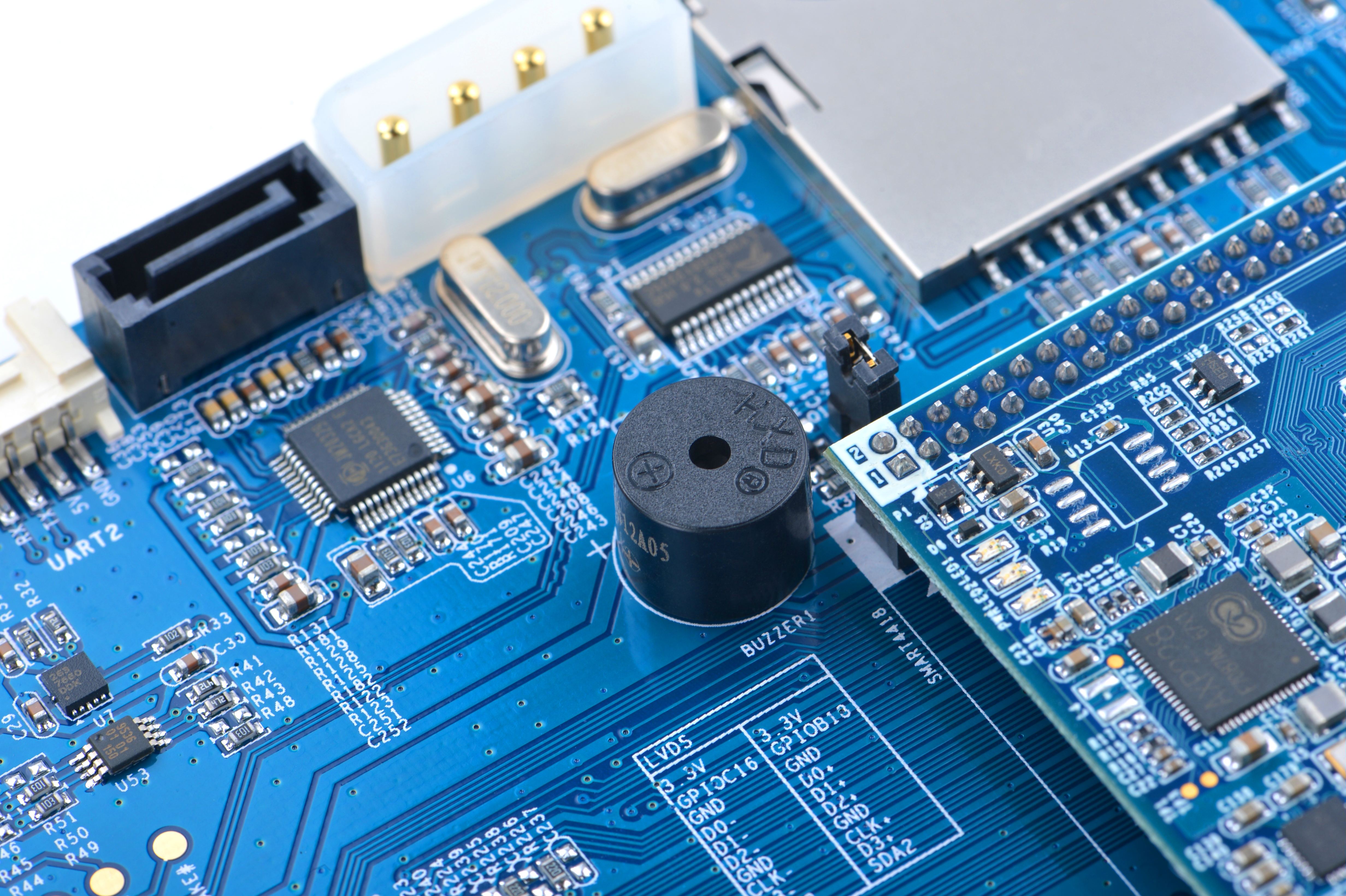
[[File:Smart4418-SDK-1606O1.jpg|thumb|500px|Overview]] | [[File:Smart4418-SDK-1606O1.jpg|thumb|500px|Overview]] | ||
[[File:Smart4418-SDK-1606F1.jpg|thumb|500px|Front]] | [[File:Smart4418-SDK-1606F1.jpg|thumb|500px|Front]] | ||
| − | * | + | * The Smart4418 SDK carrier board V1606 has various interfaces and ports like HDMI port, USB host, SD card slot, SB9 serial port, RJ-45 Ethernet port, 3.5mm audio jack, SATA interface, MiniPCIe, MicroSIM etc with support for 3G/4G Bluetooth & WiFi.In addition it has hardware resources like buzzer, user keys, RTC battery, microphone and etc for users to evaluate its performance and features. FriendlyARM designed it for sake of industrial applications by putting all commonly used interfaces and ports on one side with mounting holes for easy deployment. |
| − | * | + | * To make this carrier board applicable in various applications compared to our existing carrier boards we add more interfaces and ports such as DVP camera interface, SPI, GPIO, I2C, AP6212 WiFi & Bluetooth module, porcelain antenna, RTC seat and etc. |
| − | == | + | ==Features== |
[[File:Smart4418-SDK-Features001.jpg|thumb|600px|Features]] | [[File:Smart4418-SDK-Features001.jpg|thumb|600px|Features]] | ||
::{| class="wikitable" | ::{| class="wikitable" | ||
|- | |- | ||
| − | | | + | |SDK Carrier Board Model ||Smart4418SDK 1606 |
|- | |- | ||
| − | | | + | |Dimension || 189.8 x 118.2(mm) |
|- | |- | ||
| − | | | + | |Applicable CPU Board || [http://wiki.friendlyarm.com/wiki/index.php/Smart4418/zh Smart4418] |
|- | |- | ||
| − | |WiFi/ | + | |WiFi/Bluetooth || Onboard WiFi & Bluetooth |
|- | |- | ||
| − | | | + | |MiniPCIe Interface || For 4G modules, data service only, speech service not applicable |
|- | |- | ||
| − | | | + | |SIM Card Slot || Pop-up MicroSIM card slot |
|- | |- | ||
| − | | | + | |Antenna || Onboard porcelain antenna |
|- | |- | ||
| − | | | + | |DVP Camera Interface || 24pin, 0.5mm pitch FPC seat <br /> DVP Camera interface, ITU-R BT 601/656 8-bit |
|- | |- | ||
| − | | | + | |HDMI Interface || 1 x HDMI A Type, HDMI 1.4a (Smart4418) <br /> 1080p30 video output |
|- | |- | ||
| − | | | + | |RS232 Serial Interface || 2 x 3-wire serial port (UART0 and 3), DB9 male connector |
|- | |- | ||
| − | |USB Host || | + | |USB Host || 2 x USB A <br /> brought out from USB 2.0 hub, (USB 1.1 compatible) |
|- | |- | ||
| − | |USB | + | |USB Slave || 1 x Micro USB, data communication only |
|- | |- | ||
| − | | | + | |Audio Interface || Internal Audio<br /> supports audio recording and play <br /> 3.5mm audio jack and MIC <br /> onboard Microphone |
|- | |- | ||
| − | | | + | |Ethernet || Internal 1000/100/10M Ethernet |
|- | |- | ||
| − | | | + | |User Key || PWRKEY (power key) <br /> RST (reset) <br /> K1/K2/K3 programmable keys |
|- | |- | ||
| − | |LED || | + | |LED || 2 x GPIO LED (On Smart4418 CPU board) |
|- | |- | ||
| − | |RTC || | + | |RTC || Onboard RTC battery(CR1220) |
|- | |- | ||
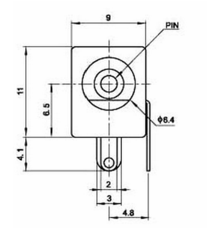
| − | | | + | |Buzzer || 1 x PWM buzzer |
|- | |- | ||
| − | | | + | |SPI Interface || CON3: 26pin ,2.54mm pitch double row pin-header |
|- | |- | ||
| − | | | + | |GPIO Header || GPIOC9, GPIOC10, GPIOC11 and GPIOC12 |
|- | |- | ||
| − | | | + | |SD Card Slot || Pop-up SD card slot |
|- | |- | ||
| − | | | + | |I2C Interface || I2C0 |
|- | |- | ||
| − | | | + | |UART Serial Interface || UART2 |
|- | |- | ||
| − | | | + | |SATA || Onboard SATA interface |
|- | |- | ||
| − | | | + | |SATA Power || Onboard SATA power interface |
|- | |- | ||
| − | | | + | |LCD Interface || LCD Interface(45pin, 0.5mm pitch FPC seat) <br /> Supports FriendlyARM one wire technology <br /> back-light adjustable <br /> Supports LCDs with capacitive touch<br /> Supports RGB888 <br /> Supports full color TFT CD |
|- | |- | ||
| − | | | + | |LCD Mounting Holes || Applicable for X710 LCD |
|- | |- | ||
| − | | | + | |LVDS Interface || 2pin, 2.0mm pitch |
|- | |- | ||
| − | | | + | |GPIO Pin-header || 30pin 2.0mm pitch double-row pin-header including 1x UART, 1x I2C, 1 x SPI, 1 x SDIO and 11 x GPIO |
|- | |- | ||
| − | | | + | |Other Resources || 1 x EEPROM, 1 x 3-Axis Digital Accelerometer |
|- | |- | ||
| − | | | + | |Power || DC 9V~24V/2A. When you connect a SATA hard disk or LVDS LCD to it a 12V/3A power adapter is required |
|} | |} | ||
| − | == | + | ==Diagram, Layout and Dimension== |
| − | === | + | ===Pin Descriptions=== |
| − | *'''26Pin UART/SPI/I2C/ | + | *'''26Pin UART/SPI/I2C/PWM Interface''' |
::{| class="wikitable" | ::{| class="wikitable" | ||
|- | |- | ||
| Line 109: | Line 110: | ||
|} | |} | ||
| − | + | *'''LVDS Interface''' | |
| − | *''' | + | |
::{| class="wikitable" | ::{| class="wikitable" | ||
|- | |- | ||
| Line 136: | Line 136: | ||
|} | |} | ||
| − | *''' | + | *'''DVP Camera Interface''' |
::{| class="wikitable" | ::{| class="wikitable" | ||
|- | |- | ||
| Line 164: | Line 164: | ||
|} | |} | ||
| − | *''' | + | *'''LCD Interface''' |
::{| class="wikitable" | ::{| class="wikitable" | ||
|- | |- | ||
|Pin# || Name || Description | |Pin# || Name || Description | ||
|- | |- | ||
| − | |1, 2 || VDD_5V || | + | |1, 2 || VDD_5V || 5V Output, it can be used to power LCD modules |
|- | |- | ||
| − | |11,20,29, 37,38,39,40, 45|| DGND || | + | |11,20,29, 37,38,39,40, 45|| DGND || Ground |
|- | |- | ||
| − | |3-10 || Blue LSB to MSB || | + | |3-10 || Blue LSB to MSB || RGB blue |
|- | |- | ||
| − | |12-19 || Green LSB to MSB || | + | |12-19 || Green LSB to MSB || RGB green |
|- | |- | ||
| − | |21-28 || Red LSB to MSB || | + | |21-28 || Red LSB to MSB || RGB red |
|- | |- | ||
| − | |30 || GPIOB25 || | + | |30 || GPIOB25 || available for users |
|- | |- | ||
| − | |31 || GPIOC15 || | + | |31 || GPIOC15 || occupied by FriendlyARM one wire technology to recognize LCD models <br> |
| − | + | and control backlight and implement resistive touch, not applicable for users | |
|- | |- | ||
| − | |32 || XnRSTOUT Form CPU || | + | |32 || XnRSTOUT Form CPU || low when system is reset |
|- | |- | ||
| − | |33 || VDEN || | + | |33 || VDEN || signal the external LCD that data is valid on the data bus |
|- | |- | ||
| − | |34 || VSYNC || | + | |34 || VSYNC || vertical synchronization |
|- | |- | ||
| − | |35 || HSYNC || | + | |35 || HSYNC || horizontal synchronization |
|- | |- | ||
| − | |36 || LCDCLK || | + | |36 || LCDCLK || LCD clock, Pixel frequency |
|- | |- | ||
| − | |41 || I2C2_SCL || | + | |41 || I2C2_SCL || I2C2 clock signal, for capacitive touch data transmission |
|- | |- | ||
| − | |42 || I2C2_SDA || | + | |42 || I2C2_SDA || I2C2 data signal, for capacitive touch data transmission |
|- | |- | ||
| − | |43 || GPIOC16 || | + | |43 || GPIOC16 || interrupt pin for capacitive touch, used with I2C2 |
|- | |- | ||
| − | |44 || NC || | + | |44 || NC || Not connected |
|} | |} | ||
| − | *''' | + | *'''SATA Interface''' |
| − | ::* | + | ::* Standard 7Pin Data Interface, 4Pin Power Interface |
::[[File:SATA-01.png|frameless|500px|]] | ::[[File:SATA-01.png|frameless|500px|]] | ||
| − | *''' | + | *'''Power Interface''' |
| − | ::* | + | ::*DC power jack, applicable for DC 5.5 * 2.1mm power jack, DC 9V~24V/2A. When you connect a SATA hard disk or LVDS LCD to it a 12V/3A power adapter is required |
::[[File:DC-005.png|frameless|200px|]] | ::[[File:DC-005.png|frameless|200px|]] | ||
| − | ::*2. | + | ::*2.54mm pitch, 2510-4P pin-header, Pin1~Pin4 description: VDD_12V, DGND, DGND, 12V_IN<br>Pin 12V_IN is connected to DC power jack, VDD_12V is connected to 12V_IN through the S1 switch |
::[[File:CON5.png]] | ::[[File:CON5.png]] | ||
| − | === | + | ===Dimensional Diagram=== |
[[File:Smart4418SDK-1606-Dimensions.png|frameless|800px|Smart4418SDK-1606-Dimensions]] | [[File:Smart4418SDK-1606-Dimensions.png|frameless|800px|Smart4418SDK-1606-Dimensions]] | ||
| − | :: | + | ::For more details refer to :[http://wiki.friendlyarm.com/wiki/images/9/90/Smart4418-1606-Dimensions%28dxf%29.zip dxf file] |
| + | |||
| + | ==Resources== | ||
| + | :SDK Carrier Board Hardware Technical Documents | ||
| + | ::[http://wiki.friendlyarm.com/wiki/images/c/c0/Smart4418SDK-1606-PCB%28brd%29.zip PCB source files], Allegro 16.5 or above<br> | ||
| + | ::[http://wiki.friendlyarm.com/wiki/images/9/90/Smart4418-1606-Dimensions%28dxf%29.zip PCB dxf file]<br> | ||
| + | ::[http://wiki.friendlyarm.com/wiki/images/1/1c/Smart4418SDK-1606-Schematic%28dsn%29.zip schematics], OrCAD 16.5 or above<br> | ||
| + | ::[http://wiki.friendlyarm.com/wiki/images/9/90/Smart4418SDK-1606-Schematic.pdf schematics in pdf] | ||
| + | :[http://wiki.friendlyarm.com/wiki/index.php/Smart4418 Smart4418 CPU board wiki]<br> | ||
| + | :[http://wiki.friendlyarm.com/wiki/images/0/0b/Smart4418-1512-Schematic.pdf Smart4418 CPU board schematics in pdf] | ||
| + | |||
| + | ==Update Log== | ||
| + | ===August-02-2016=== | ||
| + | * Released English version | ||
| − | == | + | ===Dec-08-2016=== |
| − | + | * Updated Section 2 | |
| − | + | ||
| − | + | ||
| − | + | ||
| − | + | ||
| − | + | ||
| − | + | ||
Revision as of 05:21, 29 March 2017
查看中文
Contents
1 Introduction


- The Smart4418 SDK carrier board V1606 has various interfaces and ports like HDMI port, USB host, SD card slot, SB9 serial port, RJ-45 Ethernet port, 3.5mm audio jack, SATA interface, MiniPCIe, MicroSIM etc with support for 3G/4G Bluetooth & WiFi.In addition it has hardware resources like buzzer, user keys, RTC battery, microphone and etc for users to evaluate its performance and features. FriendlyARM designed it for sake of industrial applications by putting all commonly used interfaces and ports on one side with mounting holes for easy deployment.
- To make this carrier board applicable in various applications compared to our existing carrier boards we add more interfaces and ports such as DVP camera interface, SPI, GPIO, I2C, AP6212 WiFi & Bluetooth module, porcelain antenna, RTC seat and etc.
2 Features

SDK Carrier Board Model Smart4418SDK 1606 Dimension 189.8 x 118.2(mm) Applicable CPU Board Smart4418 WiFi/Bluetooth Onboard WiFi & Bluetooth MiniPCIe Interface For 4G modules, data service only, speech service not applicable SIM Card Slot Pop-up MicroSIM card slot Antenna Onboard porcelain antenna DVP Camera Interface 24pin, 0.5mm pitch FPC seat
DVP Camera interface, ITU-R BT 601/656 8-bitHDMI Interface 1 x HDMI A Type, HDMI 1.4a (Smart4418)
1080p30 video outputRS232 Serial Interface 2 x 3-wire serial port (UART0 and 3), DB9 male connector USB Host 2 x USB A
brought out from USB 2.0 hub, (USB 1.1 compatible)USB Slave 1 x Micro USB, data communication only Audio Interface Internal Audio
supports audio recording and play
3.5mm audio jack and MIC
onboard MicrophoneEthernet Internal 1000/100/10M Ethernet User Key PWRKEY (power key)
RST (reset)
K1/K2/K3 programmable keysLED 2 x GPIO LED (On Smart4418 CPU board) RTC Onboard RTC battery(CR1220) Buzzer 1 x PWM buzzer SPI Interface CON3: 26pin ,2.54mm pitch double row pin-header GPIO Header GPIOC9, GPIOC10, GPIOC11 and GPIOC12 SD Card Slot Pop-up SD card slot I2C Interface I2C0 UART Serial Interface UART2 SATA Onboard SATA interface SATA Power Onboard SATA power interface LCD Interface LCD Interface(45pin, 0.5mm pitch FPC seat)
Supports FriendlyARM one wire technology
back-light adjustable
Supports LCDs with capacitive touch
Supports RGB888
Supports full color TFT CDLCD Mounting Holes Applicable for X710 LCD LVDS Interface 2pin, 2.0mm pitch GPIO Pin-header 30pin 2.0mm pitch double-row pin-header including 1x UART, 1x I2C, 1 x SPI, 1 x SDIO and 11 x GPIO Other Resources 1 x EEPROM, 1 x 3-Axis Digital Accelerometer Power DC 9V~24V/2A. When you connect a SATA hard disk or LVDS LCD to it a 12V/3A power adapter is required
3 Diagram, Layout and Dimension
3.1 Pin Descriptions
- 26Pin UART/SPI/I2C/PWM Interface
Pin# Name Pin# Name 1 VDD_3.3V 2 VDD_5V 3 I2C0_SDA 4 VDD_5V 5 I2C0_SCL 6 DGND 7 NC 8 UART3_TX 9 DGND 10 UART3_RX 11 NC 12 GPIOD1/PWM0 13 NC 14 DGND 15 NC 16 GPIOC13/PWM1 17 VDD_3.3V 18 NC 19 SPI0_MOSI/GPIOC31 20 DGND 21 SPI0_MISO/GPIOD0 22 NC 23 SPI0_CLK/GPIOC29 24 SPI0_CS/GPIOC30 25 DGND 26 NC
- LVDS Interface
Pin# Name Pin# Name 1 SYS_3.3V 2 SYS_3.3V 3 GPIOC16 4 GPIOB18 5 DGND 6 DGND 7 LVDS_D0- 8 LVDS_D0+ 9 LVDS_D1- 10 LVDS_D1+ 11 LVDS_D2- 12 LVDS_D2+ 13 DGND 14 DGND 15 LVDS_CLK- 16 LVDS_CLK+ 17 LVDS_D3- 18 LVDS_D3+ 19 I2C2_SCL 20 I2C2_SDA
- DVP Camera Interface
Pin# Name 1, 2 SYS_3.3V 7,9,13,15,24 DGND 3 I2C0_SCL 4 I2C0_SDA 5 GPIOB14 6 GPIOB16 8,10 NC 11 VSYNC 12 HREF 14 PCLK 16-23 Data bit7-0
- LCD Interface
Pin# Name Description 1, 2 VDD_5V 5V Output, it can be used to power LCD modules 11,20,29, 37,38,39,40, 45 DGND Ground 3-10 Blue LSB to MSB RGB blue 12-19 Green LSB to MSB RGB green 21-28 Red LSB to MSB RGB red 30 GPIOB25 available for users 31 GPIOC15 occupied by FriendlyARM one wire technology to recognize LCD models
and control backlight and implement resistive touch, not applicable for users
32 XnRSTOUT Form CPU low when system is reset 33 VDEN signal the external LCD that data is valid on the data bus 34 VSYNC vertical synchronization 35 HSYNC horizontal synchronization 36 LCDCLK LCD clock, Pixel frequency 41 I2C2_SCL I2C2 clock signal, for capacitive touch data transmission 42 I2C2_SDA I2C2 data signal, for capacitive touch data transmission 43 GPIOC16 interrupt pin for capacitive touch, used with I2C2 44 NC Not connected
- SATA Interface
- Standard 7Pin Data Interface, 4Pin Power Interface

- Power Interface
- DC power jack, applicable for DC 5.5 * 2.1mm power jack, DC 9V~24V/2A. When you connect a SATA hard disk or LVDS LCD to it a 12V/3A power adapter is required

- 2.54mm pitch, 2510-4P pin-header, Pin1~Pin4 description: VDD_12V, DGND, DGND, 12V_IN
Pin 12V_IN is connected to DC power jack, VDD_12V is connected to 12V_IN through the S1 switch
- 2.54mm pitch, 2510-4P pin-header, Pin1~Pin4 description: VDD_12V, DGND, DGND, 12V_IN

3.2 Dimensional Diagram

- For more details refer to :dxf file
4 Resources
- SDK Carrier Board Hardware Technical Documents
- PCB source files, Allegro 16.5 or above
- PCB dxf file
- schematics, OrCAD 16.5 or above
- schematics in pdf
- PCB source files, Allegro 16.5 or above
- Smart4418 CPU board wiki
- Smart4418 CPU board schematics in pdf
5 Update Log
5.1 August-02-2016
- Released English version
5.2 Dec-08-2016
- Updated Section 2