Difference between revisions of "Smart4418/6818SDK V2 1812"
From FriendlyELEC WiKi
| Line 139: | Line 139: | ||
|17 || LVDS_D3+ || LVDS D3 positive output | |17 || LVDS_D3+ || LVDS D3 positive output | ||
|- | |- | ||
| − | | | + | |19, 20 || NC || Not connected |
|- | |- | ||
|21 || I2C2_SCL || I2C2 clock, it transmits capacitive touch panel's signal | |21 || I2C2_SCL || I2C2 clock, it transmits capacitive touch panel's signal | ||
| Line 153: | Line 153: | ||
|Pin# || Name || Description | |Pin# || Name || Description | ||
|- | |- | ||
| − | |1, 2 || VDD_5V || | + | |1, 2 || VDD_5V || 5V power output, used to power LCD module |
|- | |- | ||
| − | |11,20,29,37,38,39,40|| DGND || | + | |11,20,29,37,38,39,40|| DGND || Ground |
|- | |- | ||
| − | |3-10 || Blue LSB to MSB || | + | |3-10 || Blue LSB to MSB || RGB blue |
|- | |- | ||
| − | |12-19 || Green LSB to MSB || | + | |12-19 || Green LSB to MSB || RGB green |
|- | |- | ||
| − | |21-28 || Red LSB to MSB || | + | |21-28 || Red LSB to MSB || RGB red |
|- | |- | ||
| − | |30 || GPIOB25 || | + | |30 || GPIOB25 || GPIO pin, available for users |
|- | |- | ||
| − | |31 || GPIOC15 || | + | |31 || GPIOC15 || used to detect LCD type <br> |
| − | + | used for backlight control and resistive touch panel. Users cannot change it. | |
|- | |- | ||
| − | |33 || VDEN || | + | |33 || VDEN || indicates whether RGB signals are valid. |
|- | |- | ||
| − | |34 || VSYNC || | + | |34 || VSYNC || vertical synchronization |
|- | |- | ||
| − | |35 || HSYNC || | + | |35 || HSYNC || horizontal synchronization |
|- | |- | ||
| − | |36 || LCDCLK || | + | |36 || LCDCLK || LCD clock, Pixel frequency |
|- | |- | ||
| − | |41 || I2C2_SCL || | + | |41 || I2C2_SCL || I2C2 signal, it transmits capacitive touch panel's signals |
|- | |- | ||
| − | |42 || I2C2_SDA || | + | |42 || I2C2_SDA || I2C2 data, it transmits capacitive touch panel's data |
|- | |- | ||
| − | |43 || GPIOC16 || | + | |43 || GPIOC16 || capacitive touch panel's interrupt, it should work in conjunction with I2C2 |
|- | |- | ||
| − | | | + | |32, 44 || NC || Not connected |
|} | |} | ||
| − | *''' | + | *'''LVDS Interface(on the front side of the carrier board, 2.0mm pitch 10 x 2 Pin header)''' |
::{| class="wikitable" | ::{| class="wikitable" | ||
|- | |- | ||
| Line 211: | Line 211: | ||
|} | |} | ||
| − | *'''LVDS | + | *'''LVDS Power Interface(on the front side of the carrier board, 2.0mm pitch 6Pin PH-6A connector)''' |
::{| class="wikitable" | ::{| class="wikitable" | ||
|- | |- | ||
| Line 222: | Line 222: | ||
|4 ||NC | |4 ||NC | ||
|- | |- | ||
| − | | | + | |5, 6 || DGND |
|} | |} | ||
| − | *''' | + | *'''DVP Camera Interface''' |
::{| class="wikitable" | ::{| class="wikitable" | ||
|- | |- | ||
| Line 253: | Line 253: | ||
|} | |} | ||
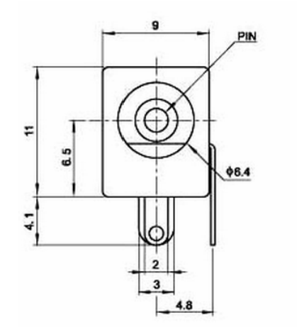
| − | *''' | + | *'''Power Port''' |
| − | ::* | + | ::*DC power port, applicable for DC 5.5 * 2.1mm power plug, 9V ~ 15V voltage input. The LVDS' backlight takes power directly from the power port. When you need to control the LVDS' backlight it is recommended to use a 12V/3A power input |
::[[File:DC-005.png|frameless|200px|]] | ::[[File:DC-005.png|frameless|200px|]] | ||
Revision as of 02:17, 23 January 2019
Contents
1 Introduction


- The Smart4418/6818SDK V2 1812 carrier board populates popular interface pins from the the Smart4418/6818 CPU board. These interface pins include HDMI, USB Host, MicroSD card slot, RS-233 port, RS485 port, RJ-45 Ethernet port, 3.5mm audio input and output, 4G module interface, MicroSIM card slot etc. It has some onboard hardware resources such as buzzer, buttons, RTC battery, microphone etc. All the popular interfaces and ports are on the same side. This layout makes it easy for customers to make a customized case for it. This carrier board can work with FriendlyElec's various LCDs such as HD702, HD702V, S430 LCD etc.
- In order for users to test and develop prototypes this Smart4418/6818SDK carrier board also populates DVP camera interface, SPI, GPIO, I2C, UART and has onboard AP6212 WiFi module, PCB antenna, IPX interface, RTC battery interface. Users can easily connect various devices to this board for testing. This meets the requirements for fast prototyping in various industrial applications.
- The Smart4418/6818SDK V2 1812 carrier board has both RGB LCD interface and LVDS LCD interface. It can work with FriendlyElec's HD702 LCD, HD702V LCD,S430 LCD. Its RGB LCD interface and LVDS LCD interface can be used to test other LCDs as well.
2 Hardware Spec

Carrier Board Type Smart4418/6818SDK V2 1812 Dimension 185 x 123(mm) Applicable Smart4418 Wi-Fi/Bluetooth Onboard Wi-Fi Bluetooth module, PCB antenna and IPX Wi-Fi antenna interface MiniPCIe Interface 4G module, only for text message, no voice service, onboard IPX to SMA antenna interface SIM Card Slot Pop-up MicroSIM card slot DVP Camera Interface 24pin, 0.5mm 5mm pitch, FPC seat
DVP Camera interface, ITU-R BT 601/656 8-bitHDMI Output 1 x HDMI A Type, supports HDMI 1.4a(Smart4418)
supports 1080p 30-frame video outputTTL Serial Port 1 x 3-wire serial port (UART0), 2.54mm pitch connector, it is by default used as a debug serial port RS485 Serial Port 1 x 3-wire serial port (UART2), 5.08mm pitch connector RS232 Serial Port 1 x 3-wire serial port (UART3), DB9 male connector USB Host 3 x USB port, populated from USB 2.0 hub(compatible with USB 1.1)
2 x USB type A port, 1 x 2.0mm pitch PH-4A connectorUSB Slave 1 x MicroUSB port, only for data transmission Audio Input and Output populated from Smart4418/Smart6818 CPU board
supports audio recording and play
3.5mm audio jack and MIC input
onboard MicrophoneEthernet populated from Smart4418/Smart6818 CPU board, 1000/100/10M Button PWRKEY(power button)
RST(reset button)
K1/K2/K3 programmable buttonsLED 2 x GPIO programmable LED(on Smart4418/Smart6818 CPU board) RTC Battery Interface Onboard RTC battery interface (CR2032) Buzzer 1 x PWM buzzer SPI 2 x SPI interface(SPI0, SPI1), 2.0mm pitch PH-4A connector
it can be used as GPIO pinsMicroSD Card Slot pop-up MicroSD card slot I2C 2 x I2C0 interface, 2.0mm pitch PH-4A connector RGB LCD Interface RGB LCD interface(45pin, 0.5mm pitch FPC seat)
supports FriendlyElec's one-wire touch technology
supports backlight control
supports capacitive touch panel
supports RGB888
supports full-color TFT LCD
populated to 22 x 2Pin 2.0mm pitch pin-headerLVDS Interface LVDS LCD interface(24pin, 0.5mm pitch FPC seat)
i2c touch panel
supports backlight control
supports capacitive touch panel
populated to 10 x 2 Pin 2.0mm pitch pin-headerLVDS power interface 2.0mm pitch PH-6A connector, it works as power input for LVDS LCD Mounting Hole applicable for FriendlyElec's HD702, HD702V and S430 LCD etc Other Resources 1 x Onboard EEPROM, 1 x 3-Axis Digital Accelerometer
4 x 2Pin 2.54mm pitch pin-header, 1 x 3.3V, 1 x boot selection used to select boot from eMMC or MicroSD(HIGH means booting from eMMC and LOW means booting from MicroSD), 1 x RST, 1 x PWRKEY, 4 x GNDPower Supply DC 9V~15V/2A, when use LVDS to control backlight it is recommended to use a 12V/3A power supply
3 Diagram, Layout and Dimension
3.1 Layout
- RGB LCD Interface(on the back side of the carrier board, 0.5mm pitch 44Pin FPC seat)
Pin# Name Description 1, 2 VDD_5V 5V output, used to power LCD 11,20,29,37,38,39,40,45 DGND Ground 3-10 Blue LSB to MSB RGB blue 12-19 Green LSB to MSB RGB green 21-28 Red LSB to MSB RGB red 30 GPIOB25 GPIO pin, available for users 31 GPIOC15 used to detect LCD type
used for backlight control and resistive touch panel. Users cannot change it.
33 VDEN indicates whether RGB signals are valid 34 VSYNC vertical synchronization 35 HSYNC horizontal synchronization 36 LCDCLK LCD clock, Pixel frequency 41 I2C2_SCL I2C2's clock. It transmits capacitive touch panel's signals 42 I2C2_SDA I2C2's data. It transmits capacitive touch panel's data 43 GPIOC16 capacitive touch panel's interrupt. It should work in conjunction with I2C2 32, 44 NC Not connected
- LVDS LCD Interface(on the back of the carrier board, 0.5mm pitch 24-Pin FPC seat)
Pin# Name Description 1-3 VDD_5V 5V power output, used to power LCD module 6,9,12,15,18,24 GND Ground 4 LVDS_D0- LVDS D0 negative output 5 LVDS_D0+ LVDS D0 positive output 7 LVDS_D1- LVDS D1 negative output 8 LVDS_D1+ LVDS D1 positive output 10 LVDS_D2- LVDS D2 negative output 11 LVDS_D2+ LVDS D2 positive output 13 LVDS_CLK- LVDS CLK negative output 14 LVDS_CLK+ LVDS CLK positive output 16 LVDS_D3- LVDS D3 negative output 17 LVDS_D3+ LVDS D3 positive output 19, 20 NC Not connected 21 I2C2_SCL I2C2 clock, it transmits capacitive touch panel's signal 22 I2C2_SDA I2C2 data, it transmits capacitive touch panel's data 23 GPIOC16 capacitive touch panel's interrupt. It should work in conjunction with I2C2
- RGB LCD Interface(on the front side of the carrier board, 2.0mm pitch 22 x 2 Pin header)
Pin# Name Description 1, 2 VDD_5V 5V power output, used to power LCD module 11,20,29,37,38,39,40 DGND Ground 3-10 Blue LSB to MSB RGB blue 12-19 Green LSB to MSB RGB green 21-28 Red LSB to MSB RGB red 30 GPIOB25 GPIO pin, available for users 31 GPIOC15 used to detect LCD type
used for backlight control and resistive touch panel. Users cannot change it.
33 VDEN indicates whether RGB signals are valid. 34 VSYNC vertical synchronization 35 HSYNC horizontal synchronization 36 LCDCLK LCD clock, Pixel frequency 41 I2C2_SCL I2C2 signal, it transmits capacitive touch panel's signals 42 I2C2_SDA I2C2 data, it transmits capacitive touch panel's data 43 GPIOC16 capacitive touch panel's interrupt, it should work in conjunction with I2C2 32, 44 NC Not connected
- LVDS Interface(on the front side of the carrier board, 2.0mm pitch 10 x 2 Pin header)
Pin# Name Pin# Name 1 SYS_3.3V 2 SYS_3.3V 3 GPIOC16 4 GPIOB18 5 DGND 6 DGND 7 LVDS_D0- 8 LVDS_D0+ 9 LVDS_D1- 10 LVDS_D1+ 11 LVDS_D2- 12 LVDS_D2+ 13 DGND 14 DGND 15 LVDS_CLK- 16 LVDS_CLK+ 17 LVDS_D3- 18 LVDS_D3+ 19 I2C2_SCL 20 I2C2_SDA
- LVDS Power Interface(on the front side of the carrier board, 2.0mm pitch 6Pin PH-6A connector)
Pin# Name 1,2 VDD_12V 3 GPIOB18 4 NC 5, 6 DGND
- DVP Camera Interface
Pin# Name 1, 2 SYS_3.3V 7,9,13,15,24 DGND 3 I2C0_SCL 4 I2C0_SDA 5 GPIOB14 6 GPIOB16 8,10 NC 11 VSYNC 12 HREF 14 PCLK 16-23 Data bit7-0
- Power Port
- DC power port, applicable for DC 5.5 * 2.1mm power plug, 9V ~ 15V voltage input. The LVDS' backlight takes power directly from the power port. When you need to control the LVDS' backlight it is recommended to use a 12V/3A power input

3.2 机械尺寸

- 详细尺寸:[http:xf%29.zip Smart4418/6818SDK V2 1812 dxf文件]
4 常用配件及应用示例
1、Smart4418/6818SDK V2 1812底板可连接Smart4418、Smart6818核心板使用
- 可以使用EC20 4G模块
- 可以使用S430 LCD屏(RGB接口)
- 可以使用HD702 LCD屏(RGB接口)
- 可以使用HD702V LCD屏(LVDS接口)


5 资源链接
- Smart4418/6818SDK V2 1812硬件设计文件
- PCB dxf文件
- Smart4418/6818SDK V2 1812原理图pdf文件
- Smart4418核心板软件和硬件详细介绍
- Smart4418原理图pdf