Smart4418
Contents
- 1 Introduction
- 2 Features
- 3 Pin Spec
- 4 Board Dimension
- 5 Carrier Board
- 6 Get Started
- 7 Play with Debian
- 8 如何编译系统
- 9 扩展连接
- 10 Smart4418 扩展TF卡分区
- 11 资源链接
1 Introduction


- The Smart4418 is a quad core Cortex A9 CPU board designed and developed by FriendlyARM for industrial applications. It uses Samsung Quad Core Cortex-A9 S5P4418 SoC with dynamic frequency scaling up to 1.4GHz. The standard model has 1GB DDR3 RAM and 8GB eMMC. It has 2.0mm pitch double row pin headers containing 174 pins in total. It works with the Smart210's SDK carrier board (V1305). This feature makes the Smart210's users easily upgrade and migrate their applications to the Smart4418. In addition FriendlyARM will soon release a Samsung Octa Core Cortex-A53 S5P6818@1.4GHz based board which is pin to pin compatible to the Smart4418 CPU board.
2 Features
- CPU: Samsung S5P4418 Quad Core Cortex-A9, with dynamic frequency scaling from 400M Hz to 1.4G Hz
- PMU Power Management Unit: AXP228. it supports software power-off and wake-up functions.
- DDR3 RAM: 1GB 32bit DDR3 RAM
- Ethernet: Gbps Ethernet(RTL8211E) with unique MAC
- eMMC: 8GB
- Audio: 1 x audio codec chip, 1 x onboard Microphone and 1 x audio jack
- LED: 1 x Power LED, 2 x GPIO LED
- Others: onboard thermistor
- PCB Dimension: 74 x 55 mm, Six-Layer
- Power: DC 5V, up to 1.2A
- OS/Software: u-boot, Android5.1, Debian8, ubuntu-core
- 3 x 2.0mm pitch double row pin header, 174 pins in total:
- USB 2.0 - Host x1, OTG x1
- Video output/Display - RGB Parallel I/F (24-bit), LVDS and HDMI 1.4a
- Video input - DVP Camera interface, ITU-R BT 601/656 8-bit and MIPI-CSI
- Audio input - Microphone
- Audio output - Audio jack (with headset detection) and HDMI audio
- Ethernet - 10/100/1000Mbps Ethernet x 1
- ADC - CPU internal ADC, 7 channels, 12-bit, range: 0 ~ 1.8V
- External interface - SDIO/MMC x2, SPI x2, I2C x3, UART x5, PWM x3, GPIOs x24
- Others - Power key input, RESET input, RESET output, RTC battery input
3 Pin Spec
P1 P2 Pin# Name Pin# Name Pin# Name Pin# Name 1 VDD_5V 2 DGND 1 UART0_TX 2 UART0_RX 3 RTC_BATT 4 GPIOB8 3 UART1_TX 4 UART1_RX 5 NRESETIN 6 GPIOC17 5 UART2_TX 6 UART2_RX 7 MMC0_CMD 8 MMC1_CMD 7 UART3_TX 8 UART3_RX 9 MMC0_CLK 10 MMC1_CLK 9 UART1_nCTS 10 UART1_nRTS 11 MMC0_D0 12 MMC1_D0 11 CAM0_D0 12 CAM0_D1 13 MMC0_D1 14 MMC1_D1 13 CAM0_D2 14 CAM0_D3 15 MMC0_D2 16 MMC1_D2 15 CAM0_D4 16 CAM0_D5 17 MMC0_D3 18 MMC1_D3 17 CAM0_D6 18 CAM0_D7 19 MMC0_CD 20 GPIOB24 19 CAM0_PCLK 20 CAM0_VSYNC 21 PWRKEY 22 SPI1_CS/GPIOC10 21 CAM0_HYNC 22 GPIOB14 23 GPIOB28/UART4_RX 24 SPI1_MISO/GPIOC11 23 GPIOB16 24 HDMI_TX1P 25 GPIOB29/UART4_TX 26 SPI1_MOSI/GPIOC12 25 HDMI_TX0P 26 HDMI_TX1N 27 GPIOB30 28 SPI1_CLK/GPIOC9 27 HDMI_TX0N 28 HDMI_TXCP 29 GPIOC15 30 GPIOC16 29 HDMI_TX2P 30 HDMI_TXCN 31 GPIOB31 32 GPIOB18 31 HDMI_TX2N 32 HDMI_HPD 33 GPIOD1/PWM0 34 I2C0_SCL 33 I2C1_SDA 34 I2C1_SCL 35 GPIOC13/PWM1 36 I2C0_SDA 35 USB_OTG_ID 36 SPI0_CS 37 USB_HOST_D- 38 I2C2_SCL 37 USB_OTG_D- 38 SPI0_MISO 39 USB_HOST_D+ 40 I2C2_SDA 39 USB_OTG_D+ 40 SPI0_MOSI 41 LCD_B0 42 LCD_B1 41 VBUS_5V 42 SPI0_CL 43 LCD_B2 44 LCD_B3 43 LVDS_CLKP 44 GPIOB25 45 LCD_B4 46 LCD_B5 45 LVDS_CLKM 46 DGND 47 LCD_B6 48 LCD_B7 47 LVDS_Y0P 48 LAN_MDI1_N 49 LCD_G0 50 LCD_G1 49 LVDS_Y0M 50 LAN_MDI1_P 51 LCD_G2 52 LCD_G3 51 LVDS_Y1P 52 LAN_MDI0_N 53 LCD_G4 54 LCD_G5 53 LVDS_Y1M 54 LAN_MDI0_P 55 LCD_G6 56 LCD_G7 55 LVDS_Y2P 56 LINK_LED 57 LCD_R0 58 LCD_R1 57 LVDS_Y2M 58 SPEED_LED 59 LCD_R2 60 LCD_R3 59 LVDS_Y3P 60 DGND 61 LCD_R4 62 LCD_R5 61 LVDS_Y3M 62 HP_DETECT 63 LCD_R6 64 LCD_R7 63 HP-R 64 HP-L 65 LCD_VSYNC 66 LCD_HSYNC 65 LAN_MDI2_P 66 LAN_MDI3_P 67 LCD_CLK 68 LCD_DE 67 LAN_MDI2_N 68 LAN_MDI3_N 69 DGND 70 BOOT_CS 69 Mic-P 70 Mic-N
P4 Pin# Name Pin# Name 1 MIPICSI_DP0 2 GPIOD8/PPM 3 MIPICSI_DN0 4 GPIOC7 5 MIPICSI_DP1 6 GPIOC8 7 MIPICSI_DN1 8 GPIOC24 9 MIPICSI_DP2 10 GPIOC28 11 MIPICSI_DN2 12 GPIOC0 13 MIPICSI_DP3 14 GPIOC1 15 MIPICSI_DN3 16 GPIOC2 17 MIPICSI_DPCLK 18 GPIOC3 19 MIPICSI_DNCLK 20 DGND 21 GPIOB9 22 ADC1 23 GPIOB26 24 ADC3 25 AliveGPIO5 26 ADC4 27 AliveGPIO3 28 ADC5 29 IO_REF_OUT,3.3V 30 ADC6 31 GPIOC14/PWM2 32 ADC7 33 NRESETOUT 34 DGND
- Note:
- VDD_5V: Supply voltage, range:4.7 ~ 5.6V. We recommend a 5V/1.2A(MAX) power. You can lower the clock to decrease the power consumption. When the clock is lowered by 200MHz the power consumption roughly decreases 0.5W .
- BOOT_CS: Boot chip selection. When it is not connected or pulled up the board boots from eMMC otherwise it boots from SD card
- NRESETIN: Reset input. Activated when it is low. A reset signal is input to CPU from this pin
- NRESETOUT: Reset output. Activated when it is low. CPU's reset signal outputs to this pin.
- RTC_BATT: RTC's input, direct connection to a 3V power source. If the CPU board is powered on the RTC seat is powered by 3.3V external power otherwise when the CPU board is not powered on it is powered by the RTC battery.
- ADC1~7: CPU internal ADC, 12-bit, 7 channels 1~7, range:0 ~ 1.8V
- 10/100M Ethernet mode: LAN_MDI1_N/P=RX-/+, LAN_MDI0_N/P=TX-/+, four pins connected to RJ45
- 10/100/1000M Ethernet mode: LAN_MDI0_N/P~LAN_MDI3N/P, all eight pins connected to RJ45
- For more details please refer to our carrier board's design:Smart210/4418 SDK
- Smart4418 Schematic in pdf
4 Board Dimension
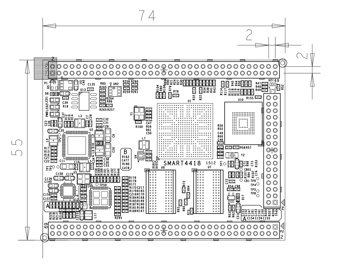
- For more details please refer to the dxf file:Smart4418-1512-Dimension(dxf).zip

5 Carrier Board
6 Get Started
6.1 Essentials You Need
Before play with your Smart4418 please get the following items ready
- Smart4418 CPU board and Smart210/4418 SDK carrier board
- Standard SD card: Class10 or above 8GB SDHC card
- A DC 5V/2A power is a must
- HDMI monitor or LCD
- USB keyboard and mouse
- A Host running Ubuntu 14.04 64 bit system
6.2 Make an Installation SD Card
6.2.1 Boot Smart4418 from SD Card
Please get the following files from here download link:
- Please get a 4G SDHC card and backup its data if necessary
For LCD or HDMI output please use the following files: nanopi2-debian-sd4g.img.zip Debian image files nanopi2-android-sd4g.img.zip Android image files Flash Utility: win32diskimager.rar Windows utility. Under Linux users can use "dd"
- Please uncompress these files. Insert an SD card(at least 4G) to a Windows PC, run the win32diskimager utility as administrator,On the utility's main window select your SD card's drive and the image files and click on "write" to start flashing the SD card.
- Please insert this card to your Smart4418's boot slot, press and hold the boot key and power on (with a 5V/2A power source). If the PWR LED is on and LED1 is blinking this indicates your Smart4418 is successfully booted.
6.2.2 Flash Image to Smart4418's eMMC
- Download RAW Image
Please get the image file: nanopi2-eflasher-sd4g.img.zip and the Windows utility: win32diskimager.rar;
- Flash RAW Image to SD Card
Please insert an SD card(at least 4G) to a Windows PC, run the win32diskimager utility as administrator,On the utility's main window select your SD card's drive and the image files and click on "write" to start flashing the SD card;
- Process RAW Image
Please go to this link [1] to downlaod Android and Debian image files(System-image-files-for-eMMC). After download please untar the ".tgz" ball and copy the files to your SD card.
OS Image Files Copy to... Android 5.1 android-lollipop-images.tgz
android-lollipop-images.tgz.hash.md5boot.img
system.img
userdata.img
cache.img
partmap.txt
images\android Debian (Jessie) debian-jessie-images.tgz
debian-jessie-images.tgz.hash.md5boot.img
rootfs.img
partmap.txt
images\debian
- Specify OS
By default the SD card's configuration file "images\FriendlyARM.ini" specifies Android to be flashed to eMMC. If you want to install Debian please make the following change:
OS = Debian
"#" is a comment
- Flash Image to Smart4418's eMMC
Please insert this card to your Smart4418, connect the board to an HDMI or LCD, switch S2 to "SDBOOT" and power on (with a 5V/2A power source) to board to start installation. You can watch the whole installation process from the HDMI or LCD. If the following messages popped up it means the installation succeeds.
Android is fused successfully.
All done.
After installation is done please do "reset" or power off and on the board to boot the board from eMMC
- You can check the LED's status to monitor the installation process too
LED Status Installation Status LED1 blinks twice continuously
LED2 offPower on normal
If installation doesn't go on LED1 will keep behaving this way and LED2 will be offLED1 and LED2 blink alternatively with each blink for 0.3s Installation going on LED1 and LED2 blink alternatively with each blink for 1.2s Installation succeeds LED1 and LED2 blink simultaneously Installation fails
6.2.3 Make Installation Card under Linux Desktop
- 1) Insert your SD card to your host running Ubuntu and check your SD card's device name
dmesg | tail
Search the messages output by "dmesg" for similar words like "sdc: sdc1 sdc2". If you can find them it means your SD card is recognized as "/dev/sdc". Or you can check that by commanding "cat /proc/partitions"
- 2) Downlaod Linux script
git clone https://github.com/friendlyarm/sd-fuse_nanopi2.git
cd sd-fuse_nanopi2
- 3) Make Android SD Card
su
./fusing.sh /dev/sdx
(Note: you need to replace "/dev/sdx" with the device name in your system)
When you run the script for the first time it will prompt you to download an image you have to hit “Y” within 10 seconds otherwise you will miss the download
- 4) Here is how to make a Debian SD card
./fusing.sh /dev/sdx debian
6.2.4 LCD/HDMI Resolution
When system boots our uboot will check whether it is connected to an LCD. If it recognizes an LCD it will configure its resolution. By default our uboot configures the display to HDMI 720P.
If you want to reset the LCD resolution you can modify file "arch/arm/plat-s5p4418/nanopi2/lcds.c" in the kernel and recompile it.
If your Smart4418 connects an HDMI monitor and it runs Android it will automatically set the resolution to an appropriate HDMI mode by checking "EDID". If your Smart4418 connects an HDMI monitor and it runs Debian by default it will set the resolution to HDMI 720P and in this case you can set it to 1080P by modifying your kernel's configuration.
6.3 Update Image Files in SD Card From PC Host
If you want to make some changes to the image files in your SD card please follow steps below otherwise you can skip this section.
Please insert your SD card to a PC host running LINUX, mount the boot and rootfs sections of the SD card and follow the steps below:
1) If you want to change your kernel command line parameters you can do it via the fw_setevn utility under "sd-fuse_nanopi2/tools":
Check the current Command Line:
cd sd-fuse_nanopi2/tools
./fw_printenv /dev/sdc | grep bootargs
Android 5.1.1_r6 starts SELinux. By default it is enforcing. You can change it this way:
./fw_setenv /dev/sdc bootargs XXX androidboot.selinux=permissive
This sets it to "permissive". The "XXX" stands for the original bootargs' value.
2) Update Kernel
Our customized uboot will check the LCD type when it boots.For a non-Android OS If it recognizes an LCD connected to the Smart4418 it will load "uImage" from "boot" otherwise it will load "uImage.hdmi".
However for Android these two files don't make any differences for whatever display device it detects. You can use your generated uImage to replace the existing one under "boot".
For Debian if your generated kernel is for LCD you need to replace the existing uImage or if your kernel is for HDMI you need to replace the existing uImage.hdmi.
6.4 Run Android or Debian
- Insert an SD card with Android/Debian image file to your Smart4418's carrier board, connect the board to an HDMI monitor, switch S2 to "SDBOOT", power on the board the Smart4418 will be booted from the SD card. If you can see the PWR LED on and the LED1 flashing it means your board is working and you will see Android/Debain loading on the HDMI monitor.
1) If you connect the Smart4418 to an HDMI monitor you need to use a USB mouse and a USB keyboard to operate. If you connect it to an LCD with capacitive touch you can operate directly on the LCD.
2)If you want to do kernel development you'd better have a serial board which allows you to operate the board via a serial terminal.
- Here is a case in which we connect a Smart4418 to a PC running Ubuntu and Minicom via a serial cable you will see system messages output to the PC’s minicom terminal

- Under Debian the password for "root" is "fa"
6.5 Login Debian via VNC or SSH
If your Smart4418 is not connected to a display device and your board runs the "-wifiap.img" image you can login your Smart4418's nanopi2-wifiap(the default password is "123456789") via a mobile phone. You can download and install a "VNC Viewer" from here on mobile phone and login the Smart4418 via VNC. Its default password is "fa123456". Here is a screenshot which shows how it looks like when users login the Smart4418 from an iPhone via VNC:

You can login via "SSH -l root 192.168.8.1" too and the default password for "root" is "fa"
To make SSH login fluent we turn off WIFI by running the following command:
iwconfig wlan0 power off
7 Play with Debian
7.1 Wireless Connection
- The following section only applies to the NanoPC-T2 which connects an HDMI or LCD
When the board runs Debian after Debian is fully loaded please click on the network icon on the GUI it will automatically search for nearby WiFi sources. Select a source from the list, click on its "Properties", type its password, save, close and then "Connect".
- The following section only applies to a Smart4418 which doesn't connect any display device(runs "-wifiap.img")
By default the system's WIFI AP mode is on therefore it cannot search and connect to a wireless router. You need to turn off the WiFi AP mode by following the instructions below:
First please set up the WIFI rounter you expect to connect to:
Log in the Smart4418 via SSH. Check the WIFI device by running the following commands. Those starting with "wlan" are WiFi devices:
ifconfig -a
By default "wlan0" is the Wifi device. You need to create a configuration file with the same name under "/etc/network/interfaces.d/". For instance you can create a "wlan0" file:
vi /etc/network/interfaces.d/wlan0
Here is the wlan0's content:
auto wlan0
iface wlan0 inet dhcp
wpa-driver nl80211
wpa-ssid YourWiFiESSID
wpa-ap-scan 1
wpa-psk YourWiFiPassword
The "YourWiFiESSID" and "YourWiFiPassword" need to be replaced with your actual ESSID and password.
If your WiFi password has special characters or you don't want your password saved as plain text you can use "wpa_passphrase" to generate a psk for your WiFi password. Here is how you can do it:
wpa_passphrase YourWiFiESSID
Follow its prompt to type your password you will get some code in the following format. The string after "psk=" is your new password:
network={
        ssid="YourWiFiESSID"
        #psk="YourWiFiPassword"
        psk=1b66ca678d6f439f7360686ff5eeb7519cdc44b76a40d96515e4eb807a6d408b
}
Now you can replace the existing password in the wlan0 file with the new one:
auto wlan0
iface wlan0 inet dhcp
wpa-driver nl80211
wpa-ssid YourWiFiESSID
wpa-ap-scan 1
wpa-psk 1b66ca678d6f439f7360686ff5eeb7519cdc44b76a40d96515e4eb807a6d408b
Next turn off the AP mode. You need to do this as root. Please run the following commands and your system will be rebooted. After your system rebooted it will automatically connect to the WiFi router you set up in your first step:
su
turn-wifi-into-apmode no
7.2 Setup Wi-Fi AP
You can follow the steps below to setup Wi-Fi AP:
turn-wifi-into-apmode yesPlease reboot the system as prompted. By default the AP's name is "nanopi2-wifiap" and the password is 123456789.
Now you are able to find the "nanopi2-wifiap" from a PC host and connect to it. If a connection is a success you will be able to SSH to this Smart4418 at "192.168.8.1":
ssh root@192.168.8.1
The password for it is "fa".
To make SSH login fluent and fast please turn off the WiFi's power saving mode by running the following command:
iwconfig wlan0 power off
You can check the WiFi mode via the following command:
cat /sys/module/bcmdhd/parameters/op_mode
If the result is "2" it means it is currently working as a WiFi AP.If you want to switch back to the Station mode you can do it this way:
turn-wifi-into-apmode no
7.3 Bluetooth
Click on the bluetooth icon on the GUI a menu will pop up:
Make discoverable enables the Smart4418 to be searched for by other bluetooth devices;
Devices... opens a search window and searches for nearby bluetooth devices(Note: the "Make discoverable" property needs to be enabled on those nearby devices);
Send Files to Device...enables the Smart4418 to send files to another bluetooth device which is a pair of the Smart4418.
7.4 安装Debian软件包
我们提供的是标准的Debian jessie系统,你可以使用apt-get等命令来安装软件包,如果板子是首次运行,需要先用以下命令更新软件包列表:
apt-get update然后就可以安装软件包了,例如要安装ftp服务器,使用以下命令:
apt-get install vsftpd如果软件包下载速度不理想,你可以编辑 /etc/apt/sources.list 更换一个更快的源服务器,这个网址[2]有一份完整的源镜像服务器列表,注意要选用一个带armhf架构的。
8 如何编译系统
8.1 安装交叉编译器
首先下载并解压编译器:
git clone https://github.com/friendlyarm/prebuilts.git
sudo mkdir -p /opt/FriendlyARM/toolchain
sudo tar xf prebuilts/gcc-x64/arm-cortexa9-linux-gnueabihf-4.9.3.tar.xz -C /opt/FriendlyARM/toolchain/
然后将编译器的路径加入到PATH中,用vi编辑vi ~/.bashrc,在末尾加入以下内容:
export PATH=/opt/FriendlyARM/toolchain/4.9.3/bin:$PATH
export GCC_COLORS=auto
执行一下~/.bashrc脚本让设置立即在当前shell窗口中生效,注意"."后面有个空格:
. ~/.bashrc这个编译器是64位的,不能在32位的Linux系统上运行,安装完成后,你可以快速的验证是否安装成功:
arm-linux-gcc -v
Using built-in specs.
COLLECT_GCC=arm-linux-gcc
COLLECT_LTO_WRAPPER=/opt/FriendlyARM/toolchain/4.9.3/libexec/gcc/arm-cortexa9-linux-gnueabihf/4.9.3/lto-wrapper
Target: arm-cortexa9-linux-gnueabihf
Configured with: /work/toolchain/build/src/gcc-4.9.3/configure --build=x86_64-build_pc-linux-gnu
--host=x86_64-build_pc-linux-gnu --target=arm-cortexa9-linux-gnueabihf --prefix=/opt/FriendlyARM/toolchain/4.9.3
--with-sysroot=/opt/FriendlyARM/toolchain/4.9.3/arm-cortexa9-linux-gnueabihf/sys-root --enable-languages=c,c++
--with-arch=armv7-a --with-tune=cortex-a9 --with-fpu=vfpv3 --with-float=hard
...
Thread model: posix
gcc version 4.9.3 (ctng-1.21.0-229g-FA)
8.2 编译U-Boot
下载U-Boot源代码并编译,注意分支是nanopi2-lollipop-mr1:
git clone https://github.com/friendlyarm/uboot_nanopi2.git
cd uboot_nanopi2
git checkout nanopi2-lollipop-mr1
make s5p4418_nanopi2_config
make CROSS_COMPILE=arm-linux-
编译成功结束后您将获得u-boot.bin,您可以通过fastboot来更新正在运行的NanoPi2板上SD的U-Boot,方法如下:
1) 在电脑上先用命令 sudo apt-get install android-tools-fastboot 安装 fastboot 工具;
2) 用串口配件连接NanoPi2和电脑,在上电启动的2秒内,在串口终端上按下回车,进入 u-boot 的命令行模式;
3) 在u-boot 命令行模式下输入命令 fastboot 回车,进入 fastboot 模式;
4) 用microUSB线连接NanoPi2和电脑,在电脑上输入以下命令烧写u-boot.bin:
fastboot flash bootloader u-boot.bin
注意:您不能直接使用dd来更新SD卡,否则有可能会导致无法正常启动。
8.3 准备mkimage
编译内核需要用到U-Boot中的工具mkimage,因此,在编译内核uImage前,您需要保证您的主机环境可以成功运行它。
你可以直接使用命令 sudo apt-get install u-boot-tools 来安装,也可以自己编译并安装:
cd uboot_nanopi2
make CROSS_COMPILE=arm-linux- tools
sudo mkdir -p /usr/local/sbin && sudo cp -v tools/mkimage /usr/local/sbin
8.4 编译Linux kernel
8.4.1 编译内核
- 下载内核源代码
git clone https://github.com/friendlyarm/linux-3.4.y.git
cd linux-3.4.y
git checkout nanopi2-lollipop-mr1
NanoPi2内核所属的分支是nanopi2-lollipop-mr1,在开始编译前先切换分支。
- 编译Android内核
make nanopi2_android_defconfig
touch .scmversion
make uImage
- 编译Debian内核
make nanopi2_linux_defconfig
touch .scmversion
make uImage
编译成功结束后,新生成的内核烧写文件为 arch/arm/boot/uImage,此内核支持HDMI 720p输出,用于替换掉SD卡boot分区下的uImage.hdmi。
如果要支持HDMI 1080p,则需要修改内核配置:
touch .scmversion
make nanopi2_linux_defconfig
make menuconfig
  Device Drivers -->
    Graphics support -->
      Nexell Graphics -->
        [ ] LCD
        [*] HDMI
        (0)   Display In  [0=Display 0, 1=Display 1]
              Resolution (1920 * 1080p)  --->
make uImage
启用LCD,同时取消HDMI,然后退出并保存配置,编译后即可获得支持LCD显示的uImage,用于替换SD卡boot分区下的uImage。
8.4.2 编译内核模块
Android包含内核模块,位于system分区的 /lib/modules/ 下,如果您有新的内核模块或者内核配置有变化,则需要重新编译。
首先编译内核源代码中的模块:
cd linux-3.4.y
make CROSS_COMPILE=arm-linux- modules
另外有2个内核模块的源代码位于Android源代码中,可使用以下命令来编译:
cd /opt/FriendlyARM/s5p4418/android
./vendor/friendly-arm/build/common/build-modules.sh
其中 “/opt/FriendlyARM/s5p4418/android” 是指Android源代码的TOP目录,使用参数“-h”可查看帮助。
编译成功结束后,会显示生成的内核模块。
8.5 编译Android
- 搭建编译环境
搭建编译Android的环境建议使用64位的Ubuntu 14.04,安装需要的包即可。
sudo apt-get install bison g++-multilib git gperf libxml2-utils make python-networkx zip
sudo apt-get install flex libncurses5-dev zlib1g-dev gawk minicom
更多说明可查看 https://source.android.com/source/initializing.html 。
- 下载源代码
Android源代码的下载需要使用repo,其安装和使用请查看 https://source.android.com/source/downloading.html 。
mkdir android && cd android
repo init -u https://github.com/friendlyarm/android_manifest.git -b nanopi2-lollipop-mr1
repo sync
其中“android”是指工作目录。
- 编译系统
source build/envsetup.sh
lunch aosp_nanopi2-userdebug
make -j8
编译成功完成后,目录 out/target/product/nanopi2/ 下包含可用于烧写的image文件。
9 扩展连接
9.1 Smart4418连接USB(FA-CAM202)200万摄像头模块
- Smart4418使用Debian系统,假设你已接好LCD屏或者HDMI,进入系统后,点击左下角的菜单键“Other”-->xawtv9,打开USB Camera软件。进入“welcome to xawtv!”,选择OK即可进行拍照。


9.2 Smart4418连接CMOS 500万摄像头模块
- Smart4418使用Android5.1系统,假设你已经接好LCD屏或者HDMI,进入系统后,直接点击“camera”图标,即可打开摄像头进行拍照。

9.3 Smart4418接USB摄像头使用OpenCV
- OpenCV的全称是Open Source Computer Vision Library,是一个跨平台的计算机视觉库。
- Smart4418跑Debian系统时,接USB Camera,可直接使用官方的OpenCV。
1、以下介绍的是Smart4418用C++使用的OpenCV:
- 首先需要保证你的Smart4418能连外网,假如你有串口,直接串口登陆超级终端(或者ssh登陆)。进入系统后,输入用户名(root),密码(fa)登陆;
- 以下命令在超级终端执行:
apt-get update
apt-get install libcv-dev libopencv-dev
2、Smart4418烧写Debian系统启动后,接上USB Camera,使用Debian系统自带的摄像头软件测试,确定摄像头能正常使用。
3、通过终端执行命令,查看你的摄像头设备:
ls /dev/video*
- 注:video9 是你的USB摄像头设备(注:video0到8均被其它设备占用了)
4、opencv的测试代码(官方C++示例代码)在 /home/fa/Documents/opencv-demo, 使用以下命令即可编译:
cd /home/fa/Documents/opencv-demo
make
编译成功后,得到可执行文件demo
5、这里特别说明:目前Smart4418的内核注册了9个video设备,而opencv的官方源码定义了最多只能使用8个Camera,所以这里需要删掉一个暂时没用到的video,我们把video0设备删掉:
rm /dev/video0
mv /dev/video9 /dev/video0
6、以下步骤需要在Smart4418上接上键盘执行:
./demo你便可以看到opencv已经用起来。
10 Smart4418 扩展TF卡分区
10.1 Smart4418 Debian系统扩展TF卡分区
- Debian扩展分区,要在pc上执行下列操作:
sudo umount /dev/sdx?
sudo parted /dev/sdx unit % resizepart 2 100 unit MB print
sudo resize2fs -f /dev/sdx2
- Android扩展分区,要在pc上执行下列操作:
sudo umount /dev/sdx?
sudo parted /dev/sdx unit % resizepart 4 100 resizepart 7 100 unit MB print
sudo resize2fs -f /dev/sdx7
(注:/dev/sdx请替换为实际的SD卡设备文件名)