Difference between revisions of "NanoPi NEO Plus2"
(→快速入门) |
(updated by API) |
||
| (70 intermediate revisions by 4 users not shown) | |||
| Line 14: | Line 14: | ||
* The NanoPi NEO Plus2 is another Allwinner based ARM board developed by FriendlyElec. It uses Allwinner's 64-bit quad-core A53 SoC with hexa-core Mali450 GPU and features 1GB of DDR3 RAM and 8GB eMMC. | * The NanoPi NEO Plus2 is another Allwinner based ARM board developed by FriendlyElec. It uses Allwinner's 64-bit quad-core A53 SoC with hexa-core Mali450 GPU and features 1GB of DDR3 RAM and 8GB eMMC. | ||
| − | * With a small size of only 40 x 52mm the NanoPi NEO Plus2 has rich on-board resources: | + | * With a small size of only 40 x 52mm the NanoPi NEO Plus2 has rich on-board resources: AP6212 WiFi & Bluetooth module, Gbps Ethernet and two USB hosts. It supports system-boot from a MicroSD card. |
* The NanoPi NEO Plus2 has a carefully designed power system and 6-layer PCB layout. These features enhance the board's heat dissipation. | * The NanoPi NEO Plus2 has a carefully designed power system and 6-layer PCB layout. These features enhance the board's heat dissipation. | ||
* The NanoPi NEO Plus2 meets popular IOT applications requirements for small size, high-speed and large throughput data transmission and high performance computing. | * The NanoPi NEO Plus2 meets popular IOT applications requirements for small size, high-speed and large throughput data transmission and high performance computing. | ||
==Hardware Spec== | ==Hardware Spec== | ||
| − | * | + | * CPU: Allwinner H5,Quad-core 64-bit high-performance Cortex A53 |
* DDR3 RAM:1GB | * DDR3 RAM:1GB | ||
* Storage: 8GB eMMC | * Storage: 8GB eMMC | ||
| − | * Network: | + | * Network: Gbps Ethernet |
* WiFi: 802.11b/g/n | * WiFi: 802.11b/g/n | ||
* Bluetooth: 4.0 dual mode | * Bluetooth: 4.0 dual mode | ||
| + | * USB Host: 2 x Independent USB Host | ||
* MicroSD Slot: 1 x Slot. It supports system booting or is used to hold a storage card | * MicroSD Slot: 1 x Slot. It supports system booting or is used to hold a storage card | ||
| − | * Audio Input/Output: | + | * Audio Input/Output: 4-Pin, 2.54mm pitch pin-header |
* MicroUSB: power input | * MicroUSB: power input | ||
* Debug Serial: 4Pin, 2.54mm pitch pin-header | * Debug Serial: 4Pin, 2.54mm pitch pin-header | ||
| − | * GPIO1:24Pin, 2. | + | * GPIO1:24Pin, 2.54mm pitch double-row pin-header containing UART, SPI, I2C and IO |
* GPIO2:12Pin, 2.54mm pitch pin-header containing USB, IR receiver,I2S and IO | * GPIO2:12Pin, 2.54mm pitch pin-header containing USB, IR receiver,I2S and IO | ||
* Power Supply: DC 5V/2A | * Power Supply: DC 5V/2A | ||
| Line 37: | Line 38: | ||
==Software Features== | ==Software Features== | ||
===UbuntuCore=== | ===UbuntuCore=== | ||
| − | * mainline kernel: Linux-4. | + | * mainline kernel: Linux-4.14 |
| + | * UbuntuCore 16.04 | ||
| + | * 64-bit OS | ||
| + | * supports FriendlyElec’s BakeBit Kit | ||
| + | * supports FriendlyElec’s NanoHAT OLED | ||
| + | * pre-installed FriendlyElec’s NanoHAT Motor Python Library | ||
| + | * pre-installed WiringPi for GPIO access | ||
| + | * pre-installed RPi.GPIO for GPIO access | ||
* npi-config: system configuration utility for setting passwords, language, timezone, hostname, SSH and auto-login. | * npi-config: system configuration utility for setting passwords, language, timezone, hostname, SSH and auto-login. | ||
| + | * networkmanager: a network utility to manage networking | ||
* auto-login with user account "pi" with access to npi-config | * auto-login with user account "pi" with access to npi-config | ||
* supports Gbps Ethernet | * supports Gbps Ethernet | ||
| Line 44: | Line 53: | ||
* supports FriendlyElec's FA-CAM202 USB camera | * supports FriendlyElec's FA-CAM202 USB camera | ||
* supports audio recording and playing | * supports audio recording and playing | ||
| + | |||
| + | ===Debian for NAS Dock=== | ||
| + | * supports FriendlyElec’s NAS Dock | ||
| + | * pre-installed OpenMediaVault | ||
==Diagram, Layout and Dimension== | ==Diagram, Layout and Dimension== | ||
| Line 117: | Line 130: | ||
|Pin# || Name || Description | |Pin# || Name || Description | ||
|- | |- | ||
| − | |1 | + | |1 || LINEOUTL || LINE-OUT Left Channel Output |
|- | |- | ||
| − | |2 || | + | |2 || LINEOUTR || LINE-OUT Right Channel Output |
|- | |- | ||
| − | |3 || | + | |3 || MICIN1N || Microphone Negative Input |
|- | |- | ||
| − | |4 || | + | |4 || MICIN1P || Microphone Positive Input |
| − | + | ||
| − | + | ||
|} | |} | ||
| Line 145: | Line 156: | ||
:'''Note:''' | :'''Note:''' | ||
::# SYS_3.3V: 3.3V power output | ::# SYS_3.3V: 3.3V power output | ||
| − | ::# VVDD_5V: 5V power input/output. The input range is 4.7V ~ 5. | + | ::# VVDD_5V: 5V power input/output. The input range is 4.7V ~ 5.5V |
::# All pins are 3.3V, output current is 5mA | ::# All pins are 3.3V, output current is 5mA | ||
| − | ::# For more details refer to the document: [http://wiki. | + | ::# For more details refer to the document: [http://wiki.friendlyelec.com/wiki/images/4/48/NanoPi_NEO_Plus2-20190328.pdf NanoPi-NEO-Plus2-V1.2-1903-Schematic.pdf] |
===Dimensional Diagram=== | ===Dimensional Diagram=== | ||
[[File:NanoPi-NEO-Plus2-1704-dimensions.png|frameless|400px|]] | [[File:NanoPi-NEO-Plus2-1704-dimensions.png|frameless|400px|]] | ||
| − | ::For more details refer to: [[http://wiki. | + | ::For more details refer to: [[http://wiki.friendlyelec.com/wiki/index.php/File:Dimensions_NanoPi_NEO_Plus2_V2_1907_PCB.rar NanoPi_NEO_Plus2_V2_1907 Dimensions of PCB file in DXF format]] |
| + | |||
| + | ==Software Features== | ||
| + | {{H5SoftwareFeature-FriendlyCore|NanoPi-NEO-Plus2}} | ||
| + | {{H5SoftwareFeature-FriendlyWrt|NanoPi-NEO-Plus2}} | ||
| + | {{H5SoftwareFeature-eFlasher|NanoPi-NEO-Plus2}} | ||
| + | |||
==Get Started== | ==Get Started== | ||
| Line 160: | Line 177: | ||
* microSD Card/TFCard: Class 10 or Above, minimum 8GB SDHC | * microSD Card/TFCard: Class 10 or Above, minimum 8GB SDHC | ||
* microUSB power. A 5V/2A power is a must | * microUSB power. A 5V/2A power is a must | ||
| − | * A | + | * A host computer running Ubuntu 18.04 64 bit system |
| − | + | {{TFCardsWeTested}} | |
| − | + | ||
| − | + | ||
| − | + | ||
| − | + | ||
| − | + | ||
| − | + | ||
| − | + | ||
| − | === | + | ===Install OS=== |
====Get Image Files==== | ====Get Image Files==== | ||
| − | Visit this link [ | + | Visit this link [http://download.friendlyelec.com/nanopineoplus2 download link] to download image files(under the "official-ROMs" directory) and the flashing utility(under the "tools" directory):<br /> |
::{| class="wikitable" | ::{| class="wikitable" | ||
| Line 179: | Line 189: | ||
|colspan=2|Image Files: | |colspan=2|Image Files: | ||
|- | |- | ||
| − | |nanopi-neo- | + | |nanopi-neo-plus2_sd_friendlycore-xenial_4.14_arm64_YYYYMMDD.img.zip || Base on UbuntuCore, kernel:Linux-4.14 |
|- | |- | ||
| − | |nanopi-neo- | + | |nanopi-neo-plus2_sd_friendlywrt_4.14_arm64_YYYYMMDD.img.zip || Base on OpenWrt, kernel:Linux-4.14 |
|- | |- | ||
| − | |nanopi-neo- | + | |nanopi-neo-plus2_eflasher_friendlycore-xenial_4.14_arm64_YYYYMMDD.img.zip || eflasher image, for flashing FriendlyCore(Linux-4.14) to eMMC |
|- | |- | ||
| − | |nanopi-neo- | + | |nanopi-neo-plus2_eflasher_friendlywrt_4.14_arm64_YYYYMMDD.img.zip || eflasher image, for flashing OpenWrt(Linux-4.14) to eMMC |
|- | |- | ||
|colspan=2|Flash Utility: | |colspan=2|Flash Utility: | ||
| Line 193: | Line 203: | ||
|} | |} | ||
| − | + | {{BurnOS-Allwinner|NanoPi-NEO-Plus2}} | |
| − | + | ||
| − | + | ||
| − | + | ||
| − | + | {{FriendlyCoreGeneral|NanoPi-NEO-Plus2}} | |
| − | + | {{FriendlyCoreAllwinnerH5|NanoPi-NEO-Plus2}} | |
| − | + | ||
| − | + | ||
| − | + | ||
| − | + | ||
| − | + | ||
| − | + | ||
| − | + | ||
| − | == | + | ===Record and Play Audio File=== |
| − | + | The NanoPi NEO Plus2 has an audio interface: 2.54mm pitch 4-pin pin-header: | |
| − | + | ||
| − | + | ||
| − | + | ||
| − | + | ||
| − | + | ||
| − | + | ||
| − | + | ||
| − | + | ||
| − | + | ||
| − | + | ||
| − | + | ||
| − | + | ||
| − | + | ||
| − | + | ||
| − | + | ||
| − | + | ||
| − | + | ||
| − | + | ||
| − | + | ||
| − | + | ||
| − | + | ||
| − | + | ||
| − | + | ||
| − | + | ||
| − | + | ||
| − | + | ||
| − | + | ||
| − | + | ||
| − | + | ||
| − | + | ||
| − | NanoPi | + | |
| − | + | ||
| − | + | ||
| − | + | ||
| − | + | ||
| − | + | ||
| − | + | ||
| − | + | ||
| − | + | ||
| − | + | ||
| − | + | ||
| − | + | ||
| − | + | ||
| − | + | ||
| − | + | ||
| − | + | ||
| − | + | ||
| − | + | ||
| − | + | ||
| − | + | ||
| − | + | ||
| − | + | ||
| − | + | ||
| − | + | ||
| − | + | ||
| − | + | ||
| − | + | ||
| − | + | ||
| − | + | ||
| − | + | ||
| − | + | ||
| − | + | ||
| − | + | ||
| − | + | ||
| − | + | ||
| − | + | ||
| − | + | ||
| − | + | ||
| − | + | ||
| − | + | ||
| − | + | ||
| − | + | ||
| − | + | ||
| − | + | ||
| − | + | ||
| − | + | ||
| − | + | ||
| − | + | ||
| − | + | ||
| − | + | ||
| − | + | ||
| − | + | ||
| − | + | ||
| − | + | ||
| − | + | ||
| − | + | ||
| − | + | ||
| − | + | ||
| − | + | ||
| − | + | ||
| − | + | ||
| − | + | ||
| − | + | ||
| − | + | ||
| − | + | ||
| − | + | ||
| − | + | ||
| − | + | ||
| − | + | ||
| − | + | ||
| − | + | ||
| − | + | ||
| − | + | ||
| − | + | ||
| − | + | ||
| − | + | ||
| − | + | ||
| − | + | ||
| − | + | ||
::{| class="wikitable" | ::{| class="wikitable" | ||
|- | |- | ||
|Pin# || Name || Description | |Pin# || Name || Description | ||
|- | |- | ||
| − | |1 || | + | |1 || LINEOUTL || LINE-OUT Left Channel Output |
|- | |- | ||
| − | |2 | + | |2 || LINEOUTR || LINE-OUT Right Channel Output |
|- | |- | ||
| − | |3 || | + | |3 || MICIN1N || Microphone Negative Input |
| − | + | ||
| − | + | ||
|- | |- | ||
| − | | | + | |4 || MICIN1P || Microphone Positive Input |
|} | |} | ||
| − | + | Here is a hardware setup for connecting an audio device to a NanoPi NEO Plus2:<br> | |
| − | [[File: | + | [[File:neo-plus2-耳麦标注.jpg|frameless|400px|耳麦标注]]<br> |
| − | + | Make sure an audio device is connected to your NEO Plus2 and then you can test audio recording and playing by running the following commands.<br> | |
| − | + | Check audio devices: | |
<syntaxhighlight lang="bash"> | <syntaxhighlight lang="bash"> | ||
$ aplay -l | $ aplay -l | ||
| Line 345: | Line 234: | ||
</syntaxhighlight> | </syntaxhighlight> | ||
| − | + | Play Audio Files: | |
<syntaxhighlight lang="bash"> | <syntaxhighlight lang="bash"> | ||
$ aplay /root/Music/test.wav -D plughw:0 | $ aplay /root/Music/test.wav -D plughw:0 | ||
</syntaxhighlight> | </syntaxhighlight> | ||
| − | + | 参数-D plughw:0表示使用设备card 0,请根据aplay -l的实际打印信息选择正确的card设备。<br> | |
| − | + | Record Audio: | |
<syntaxhighlight lang="bash"> | <syntaxhighlight lang="bash"> | ||
$ arecord -f cd -d 5 test.wav | $ arecord -f cd -d 5 test.wav | ||
</syntaxhighlight> | </syntaxhighlight> | ||
| − | + | {{OpenWrt1|NanoPi-NEO-Plus2}} | |
| − | + | {{H5-KernelHeaderFile}} | |
| − | + | {{MoreOS}} | |
| − | + | ||
| − | + | ||
| − | + | ||
| − | + | ||
| − | + | ||
| − | + | ||
| − | + | ||
| − | + | ||
| − | + | ||
| − | + | ||
| − | + | ||
| − | + | ||
| − | == | + | ==Make Your Own FriendlyCore== |
| − | === | + | ===Use Linux-4.14 BSP=== |
| − | NEO | + | The NanoPi NEO Plus2 only works with a 64-bit kernel: Linux-4.14 with Ubuntu Core 16.04. For more details about how to use mainline u-boot and Linux-4.14 refer to :[[Building U-boot and Linux for H5/H3/H2+]] <br> |
| + | ==Resources== | ||
| + | ===Schematics and Datasheets=== | ||
| + | * Schematic: | ||
| + | ** [http://wiki.friendlyelec.com/wiki/images/3/38/Schematic_NanoPi_NEO_Plus2_V2_1907.pdf NanoPi_NEO_Plus2_V2_1907_Schematic.pdf] | ||
| + | ** [http://wiki.friendlyelec.com/wiki/images/4/48/NanoPi_NEO_Plus2-20190328.pdf NanoPi_NEO_Plus2_V1.2_1903_Schematic.pdf] | ||
| + | ** [http://wiki.friendlyelec.com/wiki/images/b/bf/Schematic_NanoPi_NEO_Plus2-v1.1-1805.pdf NanoPi_NEO_Plus2_V1.1_1805_Schematic.pdf] | ||
| + | ** [http://wiki.friendlyelec.com/wiki/images/8/86/Schematic_NanoPi_NEO_Plus2-v1.0-1704.pdf NanoPi_NEO_Plus2_1704_Schematic.pdf] | ||
| + | * Dimensions: | ||
| + | ** [http://wiki.friendlyelec.com/wiki/index.php/File:Dimensions_NanoPi_NEO_Plus2_V2_1907_PCB.rar NanoPi_NEO_Plus2_V2_1907_pcb的dxf文件] | ||
| + | ** [http://wiki.friendlyelec.com/wiki/index.php/File:Dimensions_NanoPi_NEO_Plus2_V1.2-1903.rar Dimensions_NanoPi_NEO_Plus2_V1.2_1903 pcb file in dxf format] | ||
| + | ** [http://wiki.friendlyelec.com/wiki/index.php/File:Dimensions_NanoPi-NEO-Plus2-v1.1-1805.rar NanoPi_NEO_Plus2_V1.1_1805_pcb file in dxf format] | ||
| + | ** [http://wiki.friendlyelec.com/wiki/index.php/File:Dimensions_NanoPi-NEO-Plus2-1704.rar NanoPi_NEO_Plus2_1704_pcb file in dxf format] | ||
| + | * H5 Datasheet: | ||
| + | ** [http://wiki.friendlyelec.com/wiki/images/d/de/Allwinner_H5_Datasheet_V1.0.pdf Allwinner_H5_Datasheet_V1.0.pdf] | ||
| + | |||
| + | * unofficial ROM | ||
| + | ** [http://www.dietpi.com/ DietPi] | ||
| + | ** [https://www.armbian.com/download/?tx_maker=friendlyelec armbian] | ||
| + | |||
| + | * article | ||
| + | ** [https://www.cnx-software.com/2017/07/03/25-nanopi-neo-plus2-board-adds-8gb-flash-wifi-bluetooth-more-ram-and-an-extra-usb-port/] | ||
| + | ** [https://www.armbian.com/nanopi-neo-plus2/] | ||
| + | |||
| + | ==List of Version Differences== | ||
| + | * '''NanoPi NEO Plus2 Version Compare & List(Hardware)''' | ||
| + | ::{| class="wikitable" | ||
| + | |- | ||
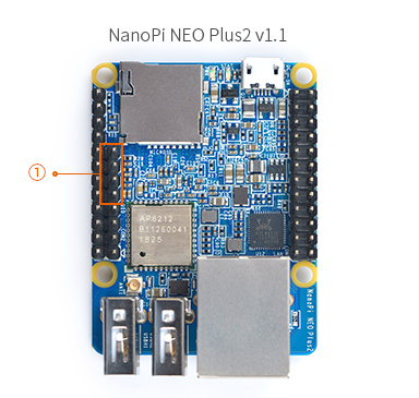
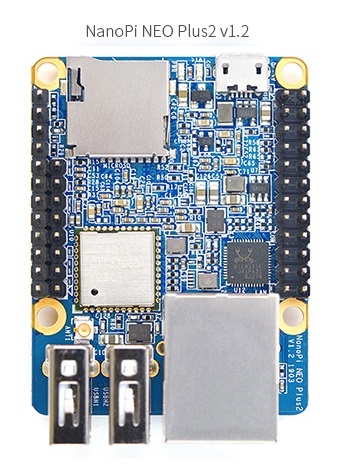
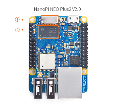
| + | ! align="center" | version || align="center" |NanoPi NEO Plus2 V1.0 1704 || align="center" |NanoPi NEO Plus2 V1.1 1805 || align="center" |NanoPi NEO Plus2 V1.2 1903 || align="center" |NanoPi NEO Plus2 V2 1907 | ||
| + | |- | ||
| + | | align="center" |Photo || [[File:NanoPi NEO Plus2-V1.0.jpg |frameless|350px]] ||[[File:NanoPi NEO Plus2-V1.1.jpg |frameless|350px]] ||[[File:NanoPi NEO Plus2-V1.2.jpg |frameless|240px]] ||[[File:NanoPi NEO Plus2-V2.jpg |frameless|360px]] | ||
| + | |- | ||
| + | | align="center" |Differences ||①NEO Plus2 v1.0's audio interface is 5Pin,2.0mm pitch pin header<br> | ||
| + | ||①NEO Plus2 v1.1's audio interface is 4Pin,2.54mm pitch pin header<br> | ||
| + | ||①增加了U14,可以软件控制USB口电源输出,详见[http://wiki.friendlyelec.com/wiki/images/4/48/NanoPi_NEO_Plus2-20190328.pdf V1.2-1903原理图]page9;<br>②排针增加了小电容,用于改善板子EMC,详见[http://wiki.friendlyelec.com/wiki/images/4/48/NanoPi_NEO_Plus2-20190328.pdf V1.2-1903原理图]page11和14。<br> | ||
| + | ||①changed MicroSD card slot type<br> ②Added 1 pcs DDR3 chip <br> | ||
| + | |} | ||
| − | == | + | ==Update Log== |
| − | === | + | ===May-30-2017=== |
| − | * | + | * Released English Version |
| − | + | ||
| − | + | ||
Latest revision as of 09:57, 21 March 2022
Contents
- 1 Introduction
- 2 Hardware Spec
- 3 Software Features
- 4 Diagram, Layout and Dimension
- 5 Software Features
- 6 Get Started
- 7 Work with FriendlyCore
- 7.1 Introduction
- 7.2 System Login
- 7.3 Configure System with npi-config
- 7.4 Develop Qt Application
- 7.5 Setup Program to AutoRun
- 7.6 Extend TF Card's Section
- 7.7 Transfer files using Bluetooth
- 7.8 WiFi
- 7.9 Setup Wi-Fi Hotspot
- 7.10 Bluetooth
- 7.11 Ethernet Connection
- 7.12 WiringPi and Python Wrapper
- 7.13 Custom welcome message
- 7.14 Modify timezone
- 7.15 Set Audio Device
- 7.16 Connect to USB Camera(FA-CAM202)
- 7.17 Check CPU's Working Temperature
- 7.18 Test Watchdog
- 7.19 Test Infrared Receiver
- 7.20 Read CHIP ID
- 7.21 Access GPIO Pins/Wirings with WiringNP
- 7.22 Run Qt Demo
- 7.23 How to install and use docker (for arm64 system)
- 7.24 Record and Play Audio File
- 8 Work with OpenWrt
- 9 Build Kernel Headers Package
- 10 More OS Support
- 11 Make Your Own FriendlyCore
- 12 Resources
- 13 List of Version Differences
- 14 Update Log
1 Introduction


- The NanoPi NEO Plus2 is another Allwinner based ARM board developed by FriendlyElec. It uses Allwinner's 64-bit quad-core A53 SoC with hexa-core Mali450 GPU and features 1GB of DDR3 RAM and 8GB eMMC.
- With a small size of only 40 x 52mm the NanoPi NEO Plus2 has rich on-board resources: AP6212 WiFi & Bluetooth module, Gbps Ethernet and two USB hosts. It supports system-boot from a MicroSD card.
- The NanoPi NEO Plus2 has a carefully designed power system and 6-layer PCB layout. These features enhance the board's heat dissipation.
- The NanoPi NEO Plus2 meets popular IOT applications requirements for small size, high-speed and large throughput data transmission and high performance computing.
2 Hardware Spec
- CPU: Allwinner H5,Quad-core 64-bit high-performance Cortex A53
- DDR3 RAM:1GB
- Storage: 8GB eMMC
- Network: Gbps Ethernet
- WiFi: 802.11b/g/n
- Bluetooth: 4.0 dual mode
- USB Host: 2 x Independent USB Host
- MicroSD Slot: 1 x Slot. It supports system booting or is used to hold a storage card
- Audio Input/Output: 4-Pin, 2.54mm pitch pin-header
- MicroUSB: power input
- Debug Serial: 4Pin, 2.54mm pitch pin-header
- GPIO1:24Pin, 2.54mm pitch double-row pin-header containing UART, SPI, I2C and IO
- GPIO2:12Pin, 2.54mm pitch pin-header containing USB, IR receiver,I2S and IO
- Power Supply: DC 5V/2A
- PCB Dimension: 40 x 52mm
- PCB Layer: 6-Layer
3 Software Features
3.1 UbuntuCore
- mainline kernel: Linux-4.14
- UbuntuCore 16.04
- 64-bit OS
- supports FriendlyElec’s BakeBit Kit
- supports FriendlyElec’s NanoHAT OLED
- pre-installed FriendlyElec’s NanoHAT Motor Python Library
- pre-installed WiringPi for GPIO access
- pre-installed RPi.GPIO for GPIO access
- npi-config: system configuration utility for setting passwords, language, timezone, hostname, SSH and auto-login.
- networkmanager: a network utility to manage networking
- auto-login with user account "pi" with access to npi-config
- supports Gbps Ethernet
- supports WiFi and Bluetooth
- supports FriendlyElec's FA-CAM202 USB camera
- supports audio recording and playing
3.2 Debian for NAS Dock
- supports FriendlyElec’s NAS Dock
- pre-installed OpenMediaVault
4 Diagram, Layout and Dimension
4.1 Layout


- GPIO Pin Description
Pin# Name Linux gpio Pin# Name Linux gpio 1 SYS_3.3V 2 VDD_5V 3 I2C0_SDA / GPIOA12 12 4 VDD_5V 5 I2C0_SCL / GPIOA11 11 6 GND 7 GPIOG11 203 8 UART1_TX / GPIOG6 198 9 GND 10 UART1_RX / GPIOG7 199 11 UART2_TX / GPIOA0 0 12 GPIOA6 6 13 UART2_RTS / GPIOA2 2 14 GND 15 UART2_CTS / GPIOA3 3 16 UART1_RTS / GPIOG8 200 17 SYS_3.3V 18 UART1_CTS / GPIOG9 201 19 SPI0_MOSI / GPIOC0 64 20 GND 21 SPI0_MISO / GPIOC1 65 22 UART2_RX / GPIOA1 1 23 SPI0_CLK / GPIOC2 66 24 SPI0_CS / GPIOC3 67
- USB/Audio/IR Pin Description
NanoPi NEO Plus2 Pin# Name Description 1 VDD_5V 5V Power Out 2 USB-DP1 USB1 DP Signal 3 USB-DM1 USB1 DM Signal 4 USB-DP2 USB2 DP Signal 5 USB-DM2 USB2 DM Signal 6 GPIOL11 / IR-RX GPIOL11 or IR Receive 7 SPDIF-OUT / GPIOA17 GPIOA17 or SPDIF-OUT 8 PCM0_SYNC / I2S0_LRC I2S / PCM Sample Rate Clock/Sync 9 PCM0_CLK / I2S0_BCK I2S / PCM Sample Rate Clock 10 PCM0_DOUT / I2S0_SDOUT I2S / PCM Serial Data Output 11 PCM0_DIN / I2S0_SDIN I2S / PCM Serial Data Input 12 GND 0V
- Audio
Pin# Name Description 1 LINEOUTL LINE-OUT Left Channel Output 2 LINEOUTR LINE-OUT Right Channel Output 3 MICIN1N Microphone Negative Input 4 MICIN1P Microphone Positive Input
- Debug Port(UART0)

Pin# Name 1 GND 2 VDD_5V 3 UART_TXD0 / GPIOA4 4 UART_RXD0 / GPIOA5 / PWM0
- Note:
- SYS_3.3V: 3.3V power output
- VVDD_5V: 5V power input/output. The input range is 4.7V ~ 5.5V
- All pins are 3.3V, output current is 5mA
- For more details refer to the document: NanoPi-NEO-Plus2-V1.2-1903-Schematic.pdf
4.2 Dimensional Diagram

- For more details refer to: [NanoPi_NEO_Plus2_V2_1907 Dimensions of PCB file in DXF format]
5 Software Features
FriendlyCore System Cross-Compiler - gcc-linaro-6.3.1-2017.02-x86_64_aarch64-linux-gnu
- it applies to 64-bit Armv8 Cortex-A, little-endian architechture. FriendlyElec uses it for its H5 based boards.
U-boot-2017.11 - It can recognize a FriendlyElec's H5 based board and load its dtb file accordingly.
- It optimizes memory settings.
- It supports voltage regulation IC sy8106a and applies only to NanoPi K1 Plus/NanoPi NEO Core2.
- It supports MAC generation from H5's CPU ID.
- It supports system booting from either SD card or eMMC and can automatically load the kernel from the booting device.
Linux-4.14 - It supports LED. You can access it via "/sys/class/leds".
- It supports GPIO. You can access it via "/sys/class/gpio/".
- It supports UART0/1/2/3. You can access it via "/dev/ttySX".
- It supports I2C0. You can access it via "/dev/i2c-X".
- It supports PWM0. You can access it via "/sys/class/pwm/". The UART0 pin is multiplexed.
- It supports I2S0. It works together with PCM5102A codec. The I2C1 pin is multiplexed.
- It supports Watchdog. You can access it via "/dev/watchX".
- It can read a CPU ID. You can access it via "/sys/bus/nvmem/devices/sunxi-sid0/nvmem".
- It supports IR Receiver. You need to connect an IR receiver to the board.
- It supports dynamic CPU voltage regulation.
- It supports USB Host0/1/2/3.
- It supports TF Card.
- It supports eMMC.
- It supports 1000M Ethernet.
- It supports H5's internal Codec and supports voice playing and recording.
- It supports USB Camera(CAM202).
- It supports popular USB WiFi Adapters.
- It supports popular USB Ethernet Adapters.
- It supports popular USB Serial Converters.
- It supports popular USB Sound Cards.
- It supports FriendlyElec's NanoHat PCM5102A.
File System - Based on UbuntuCore-16.04, it has original UbuntuCore features.
- It has popular utilties:VIM/Nano/SSHserver and etc.
- It has Qt-Embedded-4.8 and suitable for rapid product prototyping which needs a GUI.
- It has a network management utility "NetworkManager" which can automatically detect and connect to a network. For more details refer to: NetworkManager。
- It has a commandline utility "npi-config" which can be used to set a user password, language, timezone, Hostname, SSH enable/disable, auto-login, hardware interface and etc. For more details refer to Npi-config。
- It uses overlayfs.
- It expands the file system on the first system boot.
- It supports file system auto-repair on system boot.
- It supports 512MB's swap.
- It supports WiringNP which functions like Arduino's API and can be used to access NanoPi boards' gpio/i2c/spi and etc. For more details refer to: WiringNP。
- It supports FriendlyElec's BakeBit which is a set of sensor modules including hardware components(such as NanoHat Hub extension board) and software (such as BakeBit). For more details refer to BakeBit .
- It supports RPi.GPIO which can be used to access NanoPi boards' gpio with Python. For more details refer to RPi.GPIO.
- gcc-linaro-6.3.1-2017.02-x86_64_aarch64-linux-gnu
FriendlyWrt OS Cross Compiler - gcc-linaro-6.3.1-2017.02-x86_64_aarch64-linux-gnu
- Applicable for 64-bit Armv8 Cortex-A, little-endian. It has been tested and verified with FriendlyElec's Allwinner H5 boards.
U-boot-2017.11 - Same as FriendlyCore
Linux-4.14 - Same as FriendlyCore
File System - Based on OpenWrt-18.06 and keeps OpenWrt's original features;
- Based on a U-boot-2017.11 + Linux-4.14 system which is maintained by FriendlyElec
- Optimizes system initialization on a first time system boot
- Supports Huawei wifi 2 mini(E8372h)
- Supports 5G USB WiFi rtl8821cu, plug and play
- Supports Matrix-LCD2USB, by default it shows an IP address
- Utilizes overlayfs, for more details refer to How to use overlayfs on Linux
- Supports auto-extension of file system on a first time system boot
- Supports one-touch script to compile U-boot/Linux/FriendlyWrt rootfs and generate an image file, for more details refer to How to Build FriendlyWrt
- Supports flashing an image to eMMC with eflasher, for more details refer to EFlasher。
eFlasher system Cross-Compiler - gcc-linaro-6.3.1-2017.02-x86_64_aarch64-linux-gnu
- it applies to 64-bit Armv8 Cortex-A, little-endian architechture. FriendlyElec uses it for its H5 based boards.
U-boot-2017.11 - Same as FriendlyCore
Linux-4.14 - Same as FriendlyCore
File System - Based on UbuntuCore-16.04, it has original UbuntuCore features.
- It has an eFlasher utility with GUI, which is set to auto-run on system startup. For more details refer to EFlasher.
- It has an eFlasher commandline utility.
- It supports multiple OS options.
- It shows system installation process bar.
- It supports data backup from and restoration to eMMC.
- It can detect image files located on the root directory of an external storage device(e.g. USB disk).
6 Get Started
6.1 Essentials You Need
Before starting to use your NanoPi NEO Plus2 get the following items ready:
- NanoPi NEO Plus2
- microSD Card/TFCard: Class 10 or Above, minimum 8GB SDHC
- microUSB power. A 5V/2A power is a must
- A host computer running Ubuntu 18.04 64 bit system
6.2 TF Cards We Tested
To make your device boot and run fast we highly recommend you use a Class10 8GB SDHC TF card or a better one. The following cards are what we used in all our test cases presented here:
- Sandisk MicroSDHC V30 32GB Extreme Pro (Developer choice)

- SanDisk 32GB High Endurance Video MicroSDHC Card with Adapter for Dash Cam and Home Monitoring Systems (High reliability)

- SanDisk TF 8G Class10 Micro/SD High Speed TF card:

- SanDisk TF128G MicroSDXC TF 128G Class10 48MB/S:

- 川宇 8G C10 High Speed class10 micro SD card:

6.3 Install OS
6.3.1 Get Image Files
Visit this link download link to download image files(under the "official-ROMs" directory) and the flashing utility(under the "tools" directory):
Image Files: nanopi-neo-plus2_sd_friendlycore-xenial_4.14_arm64_YYYYMMDD.img.zip Base on UbuntuCore, kernel:Linux-4.14 nanopi-neo-plus2_sd_friendlywrt_4.14_arm64_YYYYMMDD.img.zip Base on OpenWrt, kernel:Linux-4.14 nanopi-neo-plus2_eflasher_friendlycore-xenial_4.14_arm64_YYYYMMDD.img.zip eflasher image, for flashing FriendlyCore(Linux-4.14) to eMMC nanopi-neo-plus2_eflasher_friendlywrt_4.14_arm64_YYYYMMDD.img.zip eflasher image, for flashing OpenWrt(Linux-4.14) to eMMC Flash Utility: win32diskimager.rar Windows utility for flashing Debian image. Under Linux users can use "dd"
6.3.2 Linux
6.3.2.1 Flash to TF
- FriendlyCore / Debian / Ubuntu / OpenWrt / DietPi are all based on a same Linux distribution and their installation methods are the same.
- Extract the Linux image and win32diskimager.rar files. Insert a TF card(at least 8G) into a Windows PC and run the win32diskimager utility as administrator. On the utility's main window select your TF card's drive, the wanted image file and click on "write" to start flashing the TF card.
Take "nanopi-neo-plus2_sd_friendlycore-xenial_4.14_arm64_YYYYMMDD.img" as an example here is the installation window. Other image files are installed on the similar window:

After it is installed you will see the following window:

- Insert this card into your board's BOOT slot and power on (with a 5V/2A power source). If the PWR LED is on and the STAT LED is blinking this indicates your board has successfully booted.
6.3.2.2 Flash to eMMC
6.3.2.2.1 Flash OS with eflasher Utility
- For more details about eflasher refer to the wiki link: EFlasher。
- Extract the eflasher Image and win32diskimager.rar files. Insert a TF card(at least 4G) into a Windows PC and run the win32diskimager utility as administrator. On the utility's main window select your TF card's drive, the wanted image file and click on "write" to start flashing the TF card.
- Insert this card into your board's BOOT slot and power on (with a 5V/2A power source). If the green LED is on and the blue LED is blinking this indicates your board has successfully booted.
- If your board doesn't support HDMI or no monitor is connected you can select an OS by running the following command:
$ su root
$ eflasher
The password for "root" is "fa".
We take "nanopi-neo-plus2_eflasher_friendlycore-xenial_4.14_arm64_YYYYMMDD.img" as an example. After you run the "eflasher" command you will see the following messages:

Type "1", select writing friendlycore system to eMMC you will see the following messages:

Type "yes" to start installation:

After it is done power off the system, take off the TF card, power on again your system will be booted from eMMC.
- If you want to flash other system to eMMC you can download the whole images-for-eflasher directory and extract the package under that directory to the FRIENDLYARM partition of an installation SD card.

7 Work with FriendlyCore
7.1 Introduction
FriendlyCore is a light Linux system without X-windows, based on ubuntu core, It uses the Qt-Embedded's GUI and is popular in industrial and enterprise applications.
Besides the regular Ubuntu Core's features FriendlyCore has the following additional features:
- it integrates Qt4.8;
- it integrates NetworkManager;
- it has bluez and Bluetooth related packages;
- it has alsa packages;
- it has npi-config;
- it has RPiGPIO, a Python GPIO module;
- it has some Python/C demo in /root/ directory;
- it enables 512M-swap partition;
7.2 System Login
- If your board is connected to an HDMI monitor you need to use a USB mouse and keyboard.
- If you want to do kernel development you need to use a serial communication board, ie a PSU-ONECOM board, which will
allow you to operate the board via a serial terminal.Here is a setup where we connect a board to a PC via the PSU-ONECOM and you can power on your board from either the PSU-ONECOM or its MicroUSB:

You can use a USB to Serial conversion board too.
Make sure you use a 5V/2A power to power your board from its MicroUSB port:

- FriendlyCore User Accounts:
Non-root User:
   User Name: pi
   Password: pi
Root:
   User Name: root
   Password: fa
The system is automatically logged in as "pi". You can do "sudo npi-config" to disable auto login.
- Update packages
$ sudo apt-get update
7.3 Configure System with npi-config
The npi-config is a commandline utility which can be used to initialize system configurations such as user password, system language, time zone, Hostname, SSH switch , Auto login and etc. Type the following command to run this utility.
$ sudo npi-config
Here is how npi-config's GUI looks like:

7.4 Develop Qt Application
Please refer to: How to Build and Install Qt Application for FriendlyELEC Boards
7.5 Setup Program to AutoRun
You can setup a program to autorun on system boot with npi-config:
sudo npi-configGo to Boot Options -> Autologin -> Qt/Embedded, select Enable and reboot.
7.6 Extend TF Card's Section
When FriendlyCore is loaded the TF card's section will be automatically extended.You can check the section's size by running the following command:
$ df -h
7.7 Transfer files using Bluetooth
Take the example of transferring files to the mobile phone. First, set your mobile phone Bluetooth to detectable status, then execute the following command to start Bluetooth search.:
hcitool scan
Search results look like:
Scanning ...
    2C:8A:72:1D:46:02   HTC6525LVW
This means that a mobile phone named HTC6525LVW is searched. We write down the MAC address in front of the phone name, and then use the sdptool command to view the Bluetooth service supported by the phone:
sdptool browser 2C:8A:72:1D:46:02
Note: Please replace the MAC address in the above command with the actual Bluetooth MAC address of the mobile phone.
This command will detail the protocols supported by Bluetooth for mobile phones. What we need to care about is a file transfer service called OBEX Object Push. Take the HTC6525LVW mobile phone as an example. The results are as follows:
Service Name: OBEX Object Push
Service RecHandle: 0x1000b
Service Class ID List:
  "OBEX Object Push" (0x1105)
Protocol Descriptor List:
  "L2CAP" (0x0100)
  "RFCOMM" (0x0003)
    Channel: 12
  "OBEX" (0x0008)
Profile Descriptor List:
  "OBEX Object Push" (0x1105)
    Version: 0x0100
As can be seen from the above information, the channel used by the OBEX Object Push service of this mobile phone is 12, we need to pass it to the obexftp command, and finally the command to initiate the file transfer request is as follows:
obexftp --nopath --noconn --uuid none --bluetooth -b 2C:8A:72:1D:46:02 -B 12 -put example.jpg
Note: Please replace the MAC address, channel and file name in the above command with the actual one.
After executing the above commands, please pay attention to the screen of the mobile phone. The mobile phone will pop up a prompt for pairing and receiving files. After confirming, the file transfer will start.
Bluetooth FAQ:
1) Bluetooth device not found on the development board, try to open Bluetooth with the following command:
rfkill unblock 02) Prompt can not find the relevant command, you can try to install related software with the following command:
apt-get install bluetooth bluez obexftp openobex-apps python-gobject ussp-push7.8 WiFi
For either an SD WiFi or a USB WiFi you can connect it to your board in the same way. The APXX series WiFi chips are SD WiFi chips. By default FriendlyElec's system supports most popular USB WiFi modules. Here is a list of the USB WiFi modules we tested:
Index Model 1 RTL8188CUS/8188EU 802.11n WLAN Adapter 2 RT2070 Wireless Adapter 3 RT2870/RT3070 Wireless Adapter 4 RTL8192CU Wireless Adapter 5 mi WiFi mt7601 6 5G USB WiFi RTL8821CU 7 5G USB WiFi RTL8812AU
You can use the NetworkManager utility to manage network. You can run "nmcli" in the commandline utility to start it. Here are the commands to start a WiFi connection:
- Change to root
$ su root
- Check device list
$ nmcli devNote: if the status of a device is "unmanaged" it means that device cannot be accessed by NetworkManager. To make it accessed you need to clear the settings under "/etc/network/interfaces" and reboot your system.
- Start WiFi
$ nmcli r wifi on- Scan Surrounding WiFi Sources
$ nmcli dev wifi- Connect to a WiFi Source
$ nmcli dev wifi connect "SSID" password "PASSWORD" ifname wlan0
The "SSID" and "PASSWORD" need to be replaced with your actual SSID and password.If you have multiple WiFi devices you need to specify the one you want to connect to a WiFi source with iface
If a connection succeeds it will be automatically setup on next system reboot.
For more details about NetworkManager refer to this link: Use NetworkManager to configure network settings
If your USB WiFi module doesn't work most likely your system doesn't have its driver. For a Debian system you can get a driver from Debian-WiFi and install it on your system. For a Ubuntu system you can install a driver by running the following commands:
$ apt-get install linux-firmware
In general all WiFi drivers are located at the "/lib/firmware" directory.
7.9 Setup Wi-Fi Hotspot
Run the following command to enter AP mode:
$ su root
$ turn-wifi-into-apmode yes
You will be prompted to type your WiFi hotspot's name and password and then proceed with default prompts.
After this is done you will be able to find this hotspot in a neadby cell phone or PC. You can login to this board at 192.168.8.1:
$ ssh root@192.168.8.1
When asked to type a password you can type "fa".
To speed up your ssh login you can turn off your wifi by running the following command:
$ iwconfig wlan0 power offTo switch back to Station mode run the following command:
$ turn-wifi-into-apmode no7.10 Bluetooth
Search for surrounding bluetooth devices by running the following command:
$ su root
$ hciconfig hci0 up
$ hcitool scan
You can run "hciconfig" to check bluetooth's status.
7.11 Ethernet Connection
If a board is connected to a network via Ethernet before it is powered on it will automatically obtain an IP with DHCP activated after it is powered up. If you want to set up a static IP refer to: Use NetworkManager to configure network settings。
7.12 WiringPi and Python Wrapper
- WiringNP: NanoPi NEO/NEO2/Air GPIO Programming with C
- RPi.GPIO : NanoPi NEO/NEO2/Air GPIO Programming with Python
7.13 Custom welcome message
The welcome message is printed from the script in this directory:
/etc/update-motd.d/
For example, to change the FriendlyELEC LOGO, you can change the file /etc/update-motd.d/10-header. For example, to change the LOGO to HELLO, you can change the following line:
TERM=linux toilet -f standard -F metal $BOARD_VENDOR
To:
TERM=linux toilet -f standard -F metal HELLO
7.14 Modify timezone
For exampe, change to Shanghai timezone:
sudo rm /etc/localtime
sudo ln -ls /usr/share/zoneinfo/Asia/Shanghai /etc/localtime
7.15 Set Audio Device
If your system has multiple audio devices such as HDMI-Audio, 3.5mm audio jack and I2S-Codec you can set system's default audio device by running the following commands.
- After your board is booted run the following commands to install alsa packages:
$ apt-get update
$ apt-get install libasound2
$ apt-get install alsa-base
$ apt-get install alsa-utils
- After installation is done you can list all the audio devices by running the following command. Here is a similar list you may see after you run the command:
$ aplay -l
card 0: HDMI
card 1: 3.5mm codec
card 2: I2S codec
"card 0" is HDMI-Audio, "card 1" is 3.5mm audio jack and "card 2" is I2S-Codec. You can set default audio device to HDMI-Audio by changing the "/etc/asound.conf" file as follows:
pcm.!default {
    type hw
    card 0
    device 0
}

ctl.!default {
    type hw
    card 0
}
If you change "card 0" to "card 1" the 3.5mm audio jack will be set to the default device.
Copy a .wav file to your board and test it by running the following command:
$ aplay /root/Music/test.wav
You will hear sounds from system's default audio device.
If you are using H3/H5/H2+ series board with mainline kernel, the easier way is using npi-config。
7.16 Connect to USB Camera(FA-CAM202)
The FA-CAM202 is a 200M USB camera. You can refer to <Connect DVP Camera (CAM500B) to Board> on how to connect a USB camera to a board.
You need to change the start.sh script and make sure it uses a correct /dev/videoX node. You can check your FA-CAM202's node by running the following commands:
$ apt-get install v4l-utils
$ v4l2-ctl -d /dev/video1 -D
Driver Info (not using libv4l2):
        Driver name   : uvcvideo
        Card type     : HC 3358+2100: HC 3358+2100
        Bus info      : usb-1c1b000.usb-1
	...
Information above indicates that /dev/video1 is the device node of the FA-CAM 202.
7.17 Check CPU's Working Temperature
You can get CPU's working temperature by running the following command:
$ cpu_freq
CPU0 online=1 temp=26581 governor=ondemand cur_freq=480000
CPU1 online=1 temp=26581 governor=ondemand cur_freq=480000
CPU2 online=1 temp=26581 governor=ondemand cur_freq=480000
CPU3 online=1 temp=26581 governor=ondemand cur_freq=480000
This message means there are currently four CPUs working. All of their working temperature is 26.5 degree in Celsius and each one's clock is 480MHz.
7.18 Test Watchdog
You can test watchdog by running the following commands:
$ cd /root/demo/watchdog/
$ gcc watchdog_demo.c -o watchdog_demo
$ ./watchdog_demo /dev/watchdog0 10
Set timeout: 10 seconds
Get timeout: 10 seconds
System will reboot in 10 second
System will reboot in 10 seconds.
7.19 Test Infrared Receiver
Note: Please Check your board if IR receiver exist.
By default the infrared function is disabled you can enable it by using the npi-config utility:
$ npi-config
    6 Advanced Options     Configure advanced settings
        A8 IR              Enable/Disable IR
            ir Enable/Disable ir[enabled]
Reboot your system and test its infrared function by running the following commands:
$ apt-get install ir-keytable
$ echo "+rc-5 +nec +rc-6 +jvc +sony +rc-5-sz +sanyo +sharp +mce_kbd +xmp" > /sys/class/rc/rc0/protocols   # Enable infrared
$ ir-keytable -t
Testing events. Please, press CTRL-C to abort.
"ir-keytable -t" is used to check whether the receiver receives infrared signals. You can use a remote control to send infrared signals to the receiver. If it works you will see similar messages as follows:
1522404275.767215: event type EV_MSC(0x04): scancode = 0xe0e43
1522404275.767215: event type EV_SYN(0x00).
1522404278.911267: event type EV_MSC(0x04): scancode = 0xe0e42
1522404278.911267: event type EV_SYN(0x00).
7.20 Read CHIP ID
As for Allwinner H2+/H3/H5/ SoCs each of these CPUs has an internal 16-btye CHIP ID which can be read by running the following commands in the Linux-4.14 kernel:
$ apt-get install bsdmainutils
$ hexdump /sys/bus/nvmem/devices/sunxi-sid0/nvmem
0000000 8082 0447 0064 04c3 3650 ce0a 1e28 2202
0000010 0002 0000 0000 0000 0000 0000 0000 0000
0000020 0000 0000 0000 0000 0000 0000 0000 0000
0000030 0000 0008 0508 0000 0000 0000 0000 0000
0000040 0000 0000 0000 0000 0000 0000 0000 0000
"8082 0447 0064 04c3 3650 ce0a 1e28 2202" is the 16-byte CHIP ID.
7.21 Access GPIO Pins/Wirings with WiringNP
The wiringPi library was initially developed by Gordon Henderson in C. It contains libraries to access GPIO, I2C, SPI, UART, PWM and etc. The wiringPi library contains various libraries, header files and a commandline utility:gpio. The gpio utility can be used to read and write GPIO pins.
FriendlyElec integrated this utility in FriendlyCore system allowing users to easily access GPIO pins. For more details refer to WiringNP WiringNP
7.22 Run Qt Demo
Run the following command
$ sudo /opt/QtE-Demo/run.sh
Here is what you expect to observe. This is an open source Qt Demo:

7.23 How to install and use docker (for arm64 system)
7.23.1 How to Install Docker
Run the following commands:
sudo apt-get update
sudo apt-get install docker.io
7.23.2 Test Docker installation
Test that your installation works by running the simple docker image:
git clone https://github.com/friendlyarm/debian-jessie-arm-docker
cd debian-jessie-arm-docker
./rebuild-image.sh
./run.sh
7.24 Record and Play Audio File
The NanoPi NEO Plus2 has an audio interface: 2.54mm pitch 4-pin pin-header:
Pin# Name Description 1 LINEOUTL LINE-OUT Left Channel Output 2 LINEOUTR LINE-OUT Right Channel Output 3 MICIN1N Microphone Negative Input 4 MICIN1P Microphone Positive Input
Here is a hardware setup for connecting an audio device to a NanoPi NEO Plus2:

Make sure an audio device is connected to your NEO Plus2 and then you can test audio recording and playing by running the following commands.
Check audio devices:
$ aplay -l
**** List of PLAYBACK Hardware Devices ****
card 0: audiocodec [audiocodec], device 0: SUNXI-CODEC sun50iw2codec-0 []
  Subdevices: 1/1
  Subdevice #0: subdevice #0
Play Audio Files:
$ aplay /root/Music/test.wav -D plughw:0
参数-D plughw:0表示使用设备card 0,请根据aplay -l的实际打印信息选择正确的card设备。
Record Audio:
$ arecord -f cd -d 5 test.wav
8 Work with OpenWrt
8.1 Introduction
OpenWrt is a highly extensible GNU/Linux distribution for embedded devices.Unlike many other distributions for routers, OpenWrt is built from the ground up to be a full-featured, easily modifiable operating system for embedded devices. In practice, this means that you can have all the features you need with none of the bloat, powered by a modern Linux kernel. For more details you can refer to:OpenWrt Website.
8.2 System Login
- Login via Serial Port
When you do kernel development you'd better get a serial communication board. After you connect your board to a serial communication board you will be able to do development work from a commandline utility.
Here is a hardware setup:
After you connect your board to a serial communication board (e.g. FriendlyElec's serial communication board) you can power the whole system from either the DC port on the serial communication board or the MicroUSB port(if there is one) on your board:
or you can use a USB to serial board and power on the whole system at the MicroUSB port with a 5V/2A power:
By default you will login as root without a password. You can use "passwd" to set a password for root.

On first boot the system will automatically extend the file system on the TF card to the max capacity:

Please wait for this to be done.
- Login via SSH
In FriendlyElec's OpenWrt system the Ethernet(eth0) is configured as WAN.
Before power on your board make sure your board is connected to a master router's LAN with an Ethernet cable and the eth0 will be assigned an IP address by DHCP.
For example, if your eth0 is assigned an IP address 192.168.1.163 you can login with SSH by running the following command:
$ ssh root@192.168.1.163
You can login without a password.
- Login via Web
You can login OpenWrt via a LuCI Web page.
After you go through all the steps in <Login via SSH> and get an IP address e.g. 192.168.1.163 for the Ethernet connection, type this IP address in a browser's address bar and you will be able to login OpenWrt-LuCI:

By default you will login as root without a password, just click on "Login" to login.
8.3 Manage Software Packages
OpenWrt has a package management utility: opkg. You can get its details by running the following command:
$ opkg
Package Manipulation:
        update                  Update list of available packages
        upgrade <pkgs>          Upgrade packages
        install <pkgs>          Install package(s)
        configure <pkgs>        Configure unpacked package(s)
        remove <pkgs|regexp>    Remove package(s)
        flag <flag> <pkgs>      Flag package(s)
         <flag>=hold|noprune|user|ok|installed|unpacked (one per invocation)

Informational Commands:
        list                    List available packages
        list-installed          List installed packages
        list-upgradable         List installed and upgradable packages
        list-changed-conffiles  List user modified configuration files
        files <pkg>             List files belonging to <pkg>
        search <file|regexp>    List package providing <file>
        find <regexp>           List packages whose name or description matches <regexp>
        info [pkg|regexp]       Display all info for <pkg>
        status [pkg|regexp]     Display all status for <pkg>
        download <pkg>          Download <pkg> to current directory
...
These are just part of the manual. Here are some popular opkg commands.
- Update Package List
Before you install a package you'd better update the package list:
$ opkg update
- Check Available Packages
$ opkg list
At the time of writing there are 3241 packages available.
- Check Installed Packages:
$ opkg list-installed
At the time of writing 124 packages have been installed.
- Install/Delete Packages:
$ opkg install <pkgs>
$ opkg remove <pkgs>
- Check Files Contained in Installed Packages:
$ opkg files <pkg>
- Install Chinese Language Package for LuCI
$ opkg install luci-i18n-base-zh-cn
- Check Changed Files:
$ opkg list-changed-conffiles
- Reference Links:
8.4 Check System Status
- Check CPU Temperature & Frequency via Commandline
$ cpu_freq
Aavailable frequency(KHz):
        480000 624000 816000 1008000
Current frequency(KHz):
        CPU0 online=1 temp=26548C governor=ondemand freq=624000KHz
        CPU1 online=1 temp=26548C governor=ondemand freq=624000KHz
        CPU2 online=1 temp=26548C governor=ondemand freq=624000KHz
        CPU3 online=1 temp=26548C governor=ondemand freq=624000KHz
These messages mean that there are four CPU cores working online simultaneously. Each core's temperature is 26.5 degrees in Celsius, the scheduling policy is on-demand and the working frequency is 624MHz. You can set the frequency by running the following command:
$ cpu_freq -s 1008000
Aavailable frequency(KHz):
        480000 624000 816000 1008000
Current frequency(KHz):
        CPU0 online=1 temp=36702C governor=userspace freq=1008000KHz
        CPU1 online=1 temp=36702C governor=userspace freq=1008000KHz
        CPU2 online=1 temp=36702C governor=userspace freq=1008000KHz
        CPU3 online=1 temp=36702C governor=userspace freq=1008000KHz
These messages mean four CPU cores are working online. Each core's temperature is 26.5 degrees. Each core's governor is on demand and the frequency is 480 MHz.
- Check System Status on OpenWrt-LuCI Web Page
After open the OpenWrt-LuCI page, go to "Statistics ---> Graphs" and you will see various system statistics e.g.:
1) System Load:

2) RAM:

3) CPU Temperature:

All the statistics listed on the Statistics page are presented by the luci-app-statistics package which uses the Collectd utility to collect data and presents them with the RRDtool utility.
If you want to get more statistics you can install other collectd-mod-* packages.
All collectd-mod-* packages use the same configuration file: /etc/config/luci_statistics.
- Reference Links:
8.5 Check Network->Interfaces Configurations
- After open the OpenWrt-LuCI page, go to "Network" ---> "Interfaces" and you will see the current network's configurations:

- All the configurations listed on the Network->Interfaces page are stored in the "/etc/config/network" file.
8.6 Check Netwrok->Wireless Configurations
- After open the OpenWrt-LuCI page, go to Network ---> Wireless and you will see the WiFi hotspot's configurations:

A default WiFi AP's hotspot name looks like "OpenWrt-10:d0:7a:de:3d:92". It doesn't have a password. You can connect your smart phone to it and browse the internet.
- All the configurations listed on the Network->Wireless page are stored in the "/etc/config/wireless" file.
8.7 USB WiFi
Currently the NanoPi NEO2 Black only works with a RTL8821CU USB WiFi dongle, plug and play. After this module is connected to the board it will by default work under AP mode and the hotspot's name is "rtl8821cu-mac address" and the password is "password";
8.8 Huawei's WiFi 2 mini(E8372H-155) Module
After this module is connected to the board it will be plug and play. The hotspot's name is "HUAWEI-8DA5". You can connect a device to the internet by connecting to this hotspot.
9 Build Kernel Headers Package
The following commands need to be executed on the development board:
9.1 Software Version
The OS image file name: nanopi-XXX_sd_friendlycore-focal_4.14_arm64_YYYYMMDD.img
$ lsb_release -a
No LSB modules are available.
Distributor ID: Ubuntu
Description:    Ubuntu 20.04 LTS
Release:        20.04
Codename:       focal

$ cat /proc/version
Linux version 4.14.111 (root@ubuntu) (gcc version 6.3.1 20170109 (Linaro GCC 6.3-2017.02)) #192 SMP Thu Jun 10 15:47:26 CST 2021
9.2 Install the required packages
sudo apt-get update
sudo apt-get install -y dpkg-dev libarchive-tools
9.3 Build Kernel Headers Package
git clone https://github.com/friendlyarm/linux -b sunxi-4.14.y --depth 1 kernel-h5
cd kernel-h5
rm -rf .git
make distclean
touch .scmversion
make CROSS_COMPILE= ARCH=arm64 sunxi_arm64_defconfig
alias tar=bsdtar
make CROSS_COMPILE= ARCH=arm64 bindeb-pkg -j4
The following message is displayed to indicate completion:
dpkg-deb: building package 'linux-headers-4.14.111' in '../linux-headers-4.14.111_4.14.111-1_arm64.deb'.
dpkg-deb: building package 'linux-libc-dev' in '../linux-libc-dev_4.14.111-1_arm64.deb'.
dpkg-deb: building package 'linux-image-4.14.111' in '../linux-image-4.14.111_4.14.111-1_arm64.deb'.
dpkg-genchanges: warning: substitution variable ${kernel:debarch} used, but is not defined
dpkg-genchanges: info: binary-only upload (no source code included)
9.4 Installation
sudo dpkg -i ../linux-headers-4.14.111_4.14.111-1_arm64.deb
9.5 Testing
To compile the pf_ring module as an example, refer to the documentation: https://www.ntop.org/guides/pf_ring/get_started/git_installation.html.
git clone https://github.com/ntop/PF_RING.git
cd PF_RING/kernel/
make
After compiling, use insmod to try to load the module:
sudo insmod ./pf_ring.ko
10 More OS Support
10.1 DietPi
![]()
DietPi is a highly optimised & minimal Debian-based Linux distribution. DietPi is extremely lightweight at its core, and also extremely easy to install and use.
Setting up a single board computer (SBC) or even a computer, for both regular or server use, takes time and skill. DietPi provides an easy way to install and run favourite software you choose.
For more information, please visit this link https://dietpi.com/docs/.
DietPi supports many of the NanoPi board series, you may download the image file from here:
11 Make Your Own FriendlyCore
11.1 Use Linux-4.14 BSP
The NanoPi NEO Plus2 only works with a 64-bit kernel: Linux-4.14 with Ubuntu Core 16.04. For more details about how to use mainline u-boot and Linux-4.14 refer to :Building U-boot and Linux for H5/H3/H2+
12 Resources
12.1 Schematics and Datasheets
- Schematic:
- Dimensions:
- H5 Datasheet:
13 List of Version Differences
- NanoPi NEO Plus2 Version Compare & List(Hardware)
version NanoPi NEO Plus2 V1.0 1704 NanoPi NEO Plus2 V1.1 1805 NanoPi NEO Plus2 V1.2 1903 NanoPi NEO Plus2 V2 1907 Photo 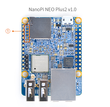
Differences ①NEO Plus2 v1.0's audio interface is 5Pin,2.0mm pitch pin header
①NEO Plus2 v1.1's audio interface is 4Pin,2.54mm pitch pin header
①增加了U14,可以软件控制USB口电源输出,详见V1.2-1903原理图page9;
②排针增加了小电容,用于改善板子EMC,详见V1.2-1903原理图page11和14。
①changed MicroSD card slot type
②Added 1 pcs DDR3 chip


14 Update Log
14.1 May-30-2017
- Released English Version