NanoPi Fire3
1 Introduction
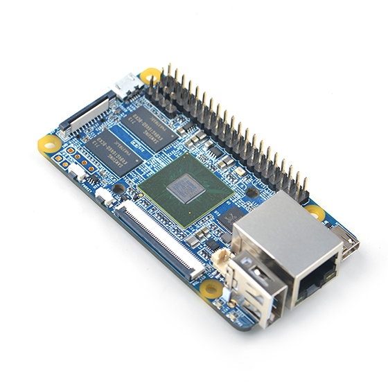
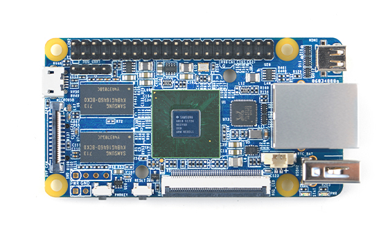
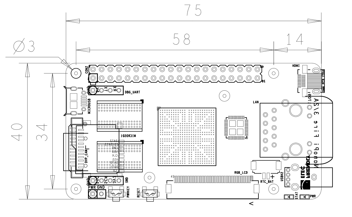
- The NanoPi Fire3 is a high performance ARM Board developed by FriendlyElec for Hobbyists, Makers and Hackers for IOT projects. It features Samsung's Cortex-A53 Octa Core S5P6818@1.4GHz SoC and 1GB 32bit DDR3 RAM. It has a Gbps Ethernet port. It boots Android and Debian from a TF card. It integrates an HDMI and LCD interface. Its adoption of the Raspberry Pi's GPIO pin header makes it compatible with both Raspberry Pi's external GPIO modules and Arduino's shield boards. Its PCB dimension is 75 x 40 mm.
2 Hardware Spec
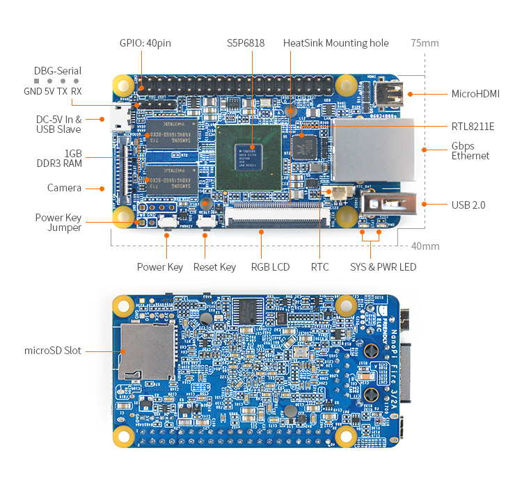
- CPU: S5P6818, 1.4GHz
- RAM: 1GBMB DDR3
- Connectivity: Gbps Ethernet port
- PMU Power Management: Implemented by a Cortex-M0 MCU, support software power-off, sleep and wakeup functions
- USB 2.0 Type A x 1
- Debug Serial Port/UART0 x 1
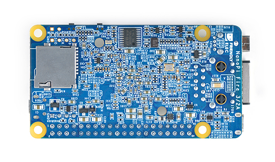
- microSD Slot x 1
- microUSB x 1: for data transmission and power input
- LCD Interface: 0.5 mm pitch SMT FPC seat, for full-color LCD (RGB: 8-8-8)
- HDMI: HDMI 1.4A, microHDMI(Type-D), 1080P60
- DVP Camera Interface: 0.5mm spacing FPC socket. It includes ITU-R BT 601/656 8-bit, I2C and IO
- GPIO: 2.54mm spacing 40pin, compatible with Raspberry Pi's GPIO. It includes UART, SPI, I2C, PWM, IO etc
- Button: Power Button x 1, Reset Button x 1
- LED: LED for Power Indication x 1, System LED x 1
- RTC: RTC Battery Seat
- PCB Dimension: 75 x 40mm
- Power: DC 5V/2A
- Temperature measuring range: -20℃ to 80℃
- OS: Android, Debian and FriendlyCore(Linux Kernel 4.4 + Qt5.9 + OpenGL2.0)
3 Diagram, Layout and Dimension
3.1 Layout
- GPIO Pin Spec
Pin# Name Pin# Name 1 SYS_3.3V 2 VDD_5V 3 I2C0_SDA 4 VDD_5V 5 I2C0_SCL 6 DGND 7 GPIOD8/PPM 8 UART3_TXD/GPIOD21 9 DGND 10 UART3_RXD/GPIOD17 11 UART4_TX/GPIOB29 12 GPIOD1/PWM0 13 GPIOB30 14 DGND 15 GPIOB31 16 GPIOC14/PWM2 17 SYS_3.3V 18 GPIOB27 19 SPI0_MOSI/GPIOC31 20 DGND 21 SPI0_MISO/GPIOD0 22 UART4_RX/GPIOB28 23 SPI0_CLK/GPIOC29 24 SPI0_CS/GPIOC30 25 DGND 26 GPIOB26 27 I2C1_SDA 28 I2C1_SCL 29 GPIOC8 30 DGND 31 GPIOC7 32 GPIOC28 33 GPIOC13/PWM1 34 DGND 35 SPI2_MISO/GPIOC11 36 SPI2_CS/GPIOC10 37 AliveGPIO3 38 SPI2_MOSI/GPIOC12 39 DGND 40 SPI2_CLK/GPIOC9
- Debug Port(UART0)
Pin# Name 1 DGND 2 VDD_5V 3 UART_TXD0 4 UART_RXD0
- DVP Camera Interface Pin Spec
Pin# Name 1, 2 SYS_3.3V 7,9,13,15,24 DGND 3 I2C0_SCL 4 I2C0_SDA 5 GPIOB14 6 GPIOB16 8 GPIOC13/PWM1 10 NC 11 VSYNC 12 HREF 14 PCLK 16-23 Data bit7-0
- RGB LCD Interface Pin Spec
Pin# Name Description 1, 2 VDD_5V 5V output, LCD power 11,20,29, 37,38,39,40, 45 DGND ground 3-10 Blue LSB to MSB RGB Blue 12-19 Green LSB to MSB RGB Green 21-28 Red LSB to MSB RGB Red 30 GPIOB25 available for users 31 GPIOC15 occupied by FriendlyARM one wire technology to recognize LCD models and control backlight and implement resistive touch, not applicable for users 32 XnRSTOUT Form CPU low when system is reset 33 VDEN signal the external LCD that data is valid on the data bus 34 VSYNC vertical synchronization 35 HSYNC horizontal synchronization 36 LCDCLK LCD clock, Pixel frequency 41 I2C2_SCL I2C2 clock signal, for capacitive touch's data transmission 42 I2C2_SDA I2C2 data signal, for capacitive touch's data transmission 43 GPIOC16 interrupt pin for capacitive touch, used with I2C2 44 NC not connected
- RTC
- 3.35uA@3V
- USB 2.0 Host
- with 1A over current protection
- Note
- SYS_3.3V: 3.3V power output
- VDD_5V: 5V power input/output. When the external device’s power is greater than the MicroUSB’s the external device is charging the board otherwise the board powers the external device. The input range is 4.7V ~ 5.5V
- For more details please refer to the schematic. NanoPi Fire3 1709 Schematic.pdf
3.2 Board Dimension
- For more details please refer to the dxf drawimg document.NanoPi Fire3 1709 dxf文件
4 Get Started
4.1 Essentials You Need
Before starting to use your NanoPi Fire3 get the following items ready
- NanoPi Fire3
- SD Card: Class 10 or Above, minimum 8GB SDHC
- A DC 5V/2A power is a must
- HDMI monitor or LCD
- USB keyboard, mouse and possible a USB hub(or a TTL to serial board)
- A host computer running Ubuntu 14.04 64 bit system
4.2 Make an Installation SD Card
4.2.1 Boot NanoPi Fire3 from SD Card
Get the following files from here to download necessary files:
- Get a 8G SDHC card and backup its data if necessary
Image Files: s5p6818-debian-sd4g-YYYYMMDD.img Debian image files s5p6818-android-sd4g-YYYYMMDD.img Android image files s5p6818-FriendlyCore-Xenial-4.4-YYYYMMDD.img Ubuntu Core + QT image files Flash Utility: win32diskimager.rar Windows utility. Under Linux users can use "dd"
- Uncompress these files. Insert an SD card(at least 8G) into a Windows PC and run the win32diskimager utility as administrator. On the utility's main window select your SD card's drive, the wanted image file and click on "write" to start flashing the SD card.
- Insert this card into your NanoPi Fire3's boot slot, press and hold the boot key and power on (with a 5V/2A power source). If the PWR LED is on and LED1 is blinking this indicates your NanoPi Fire3 has successfully booted.
4.2.2 Make Installation Card under Linux Desktop
- 1) Insert your SD card into a host computer running Ubuntu and check your SD card's device name
dmesg | tail
Search the messages output by "dmesg" for similar words like "sdc: sdc1 sdc2". If you can find them it means your SD card has been recognized as "/dev/sdc". Or you can check that by commanding "cat /proc/partitions"
- 2) Downlaod Linux script
git clone https://github.com/friendlyarm/sd-fuse_s5p6818.git
cd sd-fuse_s5p6818
- 3) Make Android SD Card
su
./fusing.sh /dev/sdx
(Note: you need to replace "/dev/sdx" with the device name in your system)
When you run the script for the first time it will prompt you to download an image you have to hit “Y” within 10 seconds otherwise you will miss the download
- 4) Here is how to make a Debian SD card
./fusing.sh /dev/sdx debian
4.2.3 Extend NanoPi Fire3's SD Card Section
- When Debian/Ubuntu is loaded the SD card's section will be automatically extended.
- When Android is loaded you need to run the following commands on your host PC to extend your SD card's section:
sudo umount /dev/sdx?
sudo parted /dev/sdx unit % resizepart 4 100 resizepart 7 100 unit MB print
sudo resize2fs -f /dev/sdx7
(Note: you need to replace "/dev/sdx" with the device name in your system)
4.2.4 LCD/HDMI Resolution
When the system boots our uboot will check whether it is connected to an LCD or to an HDMI monitor. If it recognizes an LCD it will configure its resolution. Our uboot defaults to the HDMI 720P configuration.
If you want to modify the LCD resolution you can modify file "arch/arm/plat-s5p6818/nanopi3/lcds.c" in the kernel and recompile it.
If your NanoPi Fire3 is connected to an HDMI monitor and it runs Android it will automatically set the resolution to an appropriate HDMI mode by checking the "EDID". If your NanoPi Fire3 is connected to an HDMI monitor and it runs Debian by default it will set the resolution to the HDMI 720P configuration. If you want to modify the HDMI resolution to 1080P modify your kernel's configuration as explained above.
4.3 Update Image Files in SD Card From PC Host
If you want to make some changes to the image files in your SD card follow the steps below otherwise you can skip this section.
Insert your SD card into a host PC running Linux, mount the boot and rootfs sections of the SD card and follow the steps below:
1) If you want to change your kernel command line parameters you can do it via the fw_setevn utility under "sd-fuse_s5p6818/tools".
Check the current Command Line:
cd sd-fuse_s5p6818/tools
./fw_printenv /dev/sdc | grep bootargs
Android 5.1.1_r6 starts SELinux. By default it is enforcing. You can change it this way:
./fw_setenv /dev/sdc bootargs XXX androidboot.selinux=permissive
This sets it to "permissive". The "XXX" stands for the original bootargs' value.
2) Update Kernel
Our customized uboot will check the LCD type when it boots.
For Android it doesn't make any difference which display device is detected. You can use your generated uImage to replace the existing one under "boot".
For Debian if your generated kernel is for an LCD you need to replace the existing uImage or if your kernel is for an HDMI monitor you need to replace the existing uImage.hdmi.
4.4 Run Android or Debian
- Insert an SD card with Android/Debian image file into your NanoPi Fire3, connect the board to an HDMI monitor, press and hold the boot key, power on the board the NanoPi Fire3 will boot from the SD card. If you can see the PWR LED on and the LED1 flashing it means your board is working and you will see Android/Debain being loaded on the HDMI monitor.
1) If you connect the NanoPi Fire3 to an HDMI monitor you need to use a USB mouse and a USB keyboard to operate. If you connect it to an LCD with capacitive touch you can operate directly on the LCD.
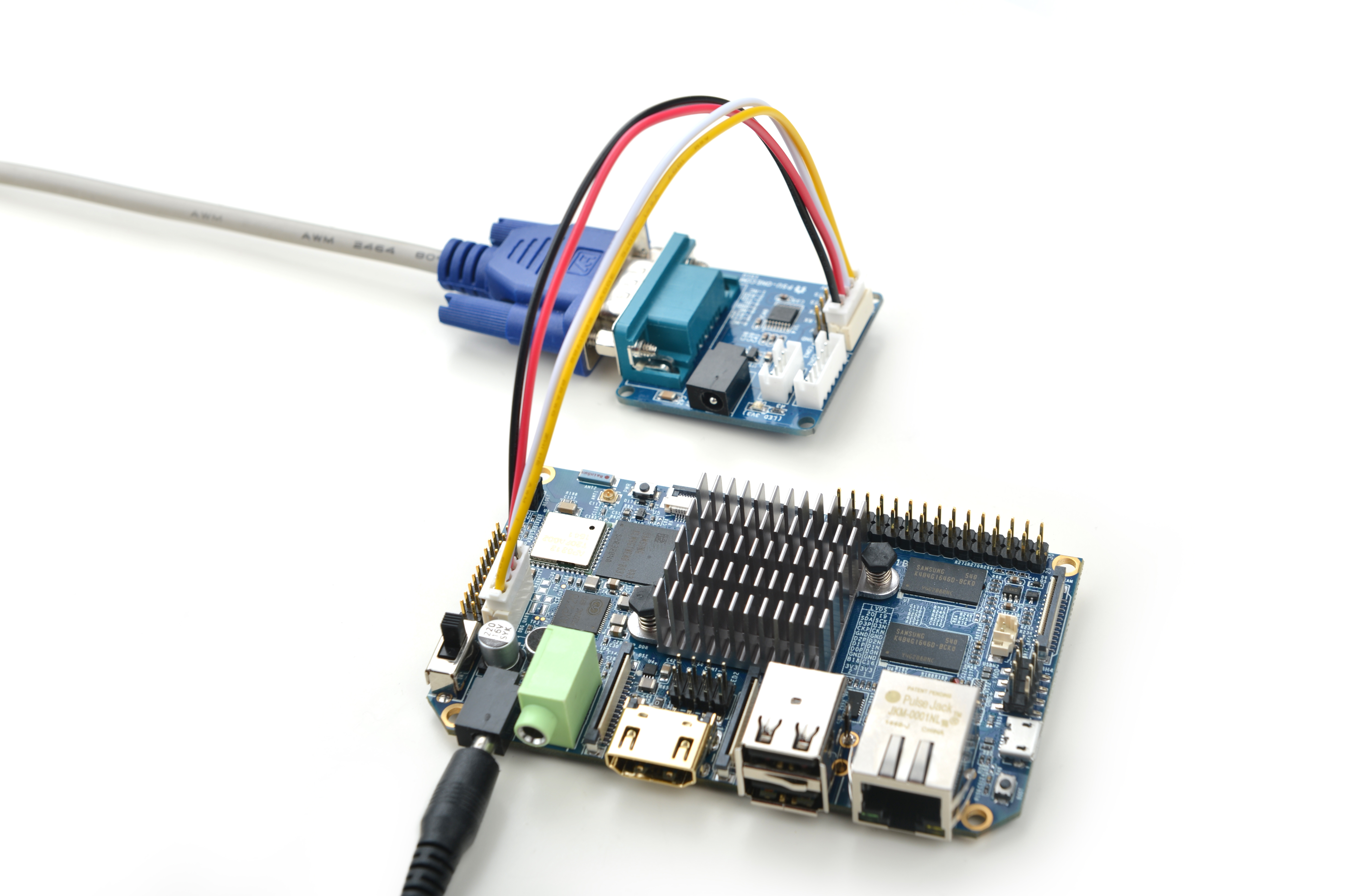
2)If you want to do kernel development you need to use a serial communication board, ie a PSU-ONECOM board, which will allow you to operate the board via a serial terminal
- Here is a setup where we connect a NanoPi Fire3 to a PC running Ubuntu and Minicom via a serial cable you will see system messages output to the PC’s minicom terminal:
- Under Debian the password for "root" is "fa"
