Difference between revisions of "NanoPi Duo2 IoT-Box"
(→软件使用) |
(→Applications) |
||
| Line 77: | Line 77: | ||
==Applications== | ==Applications== | ||
| − | === | + | ===Work with GSM/GPRS Module=== |
Insert a SIM card and connect a GSM/GPRS antenna to the board:<br /> | Insert a SIM card and connect a GSM/GPRS antenna to the board:<br /> | ||
| − | === | + | ===Work with USB Host=== |
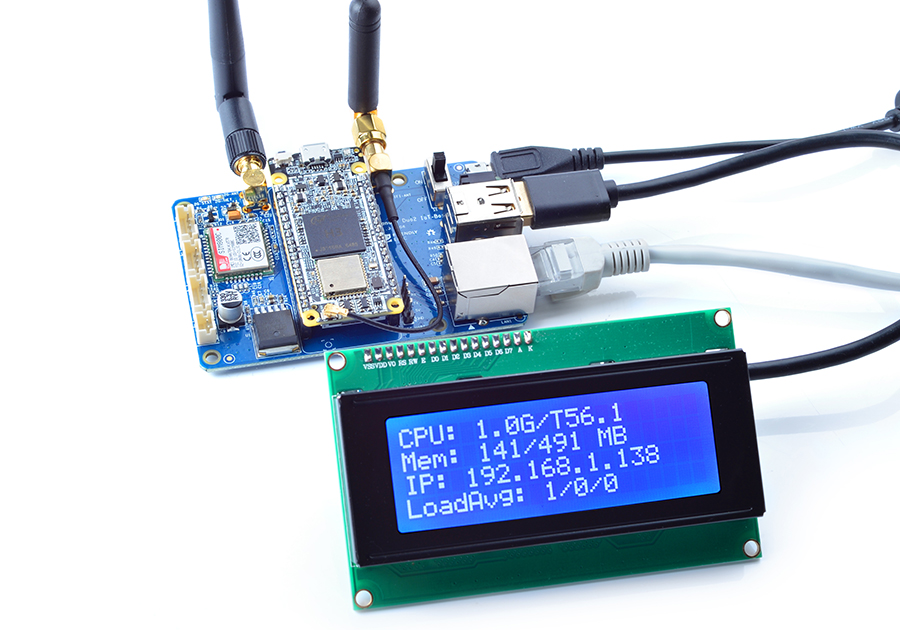
| − | NanoPi Duo2 IoT- | + | You can connect a USB device e.g. Matrix - LCD2USB to the NanoPi Duo2 IoT-Box board as follows:<br /> |
[[File:Matrix-LCD2USB_NanoPi Duo2 IoT-Box.jpg|frameless|600px|连接Matrix - LCD2USB]] | [[File:Matrix-LCD2USB_NanoPi Duo2 IoT-Box.jpg|frameless|600px|连接Matrix - LCD2USB]] | ||
| − | === | + | ===Work with Audio Input & Output=== |
1、可使用以下命令录音: | 1、可使用以下命令录音: | ||
<syntaxhighlight lang="bash"> | <syntaxhighlight lang="bash"> | ||
Revision as of 10:06, 11 October 2018
Contents
1 Introduction
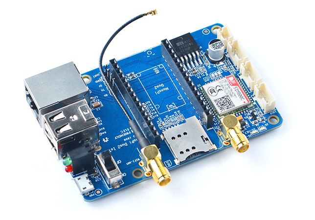
- The NanoPi Duo2 IoT-Box is a dedicated carrier board for the NanoPi Duo2. It populates Ethernet port, serial port, audio and USB etc.
- It has an onboard quad-band GSM/GPRS module SIM800C.
- It has 2.0mm I2C interface, UART interface, audio interface and CVBS interface etc and can work with various external modules.
- Its MicroUSB port is only used as power input. And a power switch is added too.
- It has one power LED and one GPIO accessed LED.
- It populates the two USB ports of the NanoPi Duo2.
- It populates the serial ports and Ethernet port of the NanoPi Duo2.
- It has an IPX to SMA antenna converter for WiFi antennas.
2 Hardware Spec
- Onboard quad-band GSM/GPRS module
- 2 x USB Host
- Serial port and Ethernet port
- Audio input and output
- MicroUSB power input and a power switch
- IPX to SMA WiFi converter
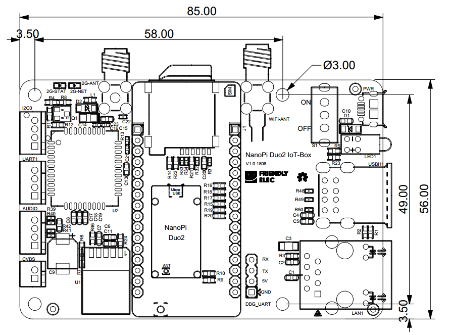
- PCB dimension (mm): 85x56
2.1 Layout
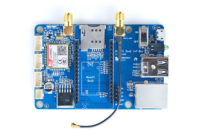
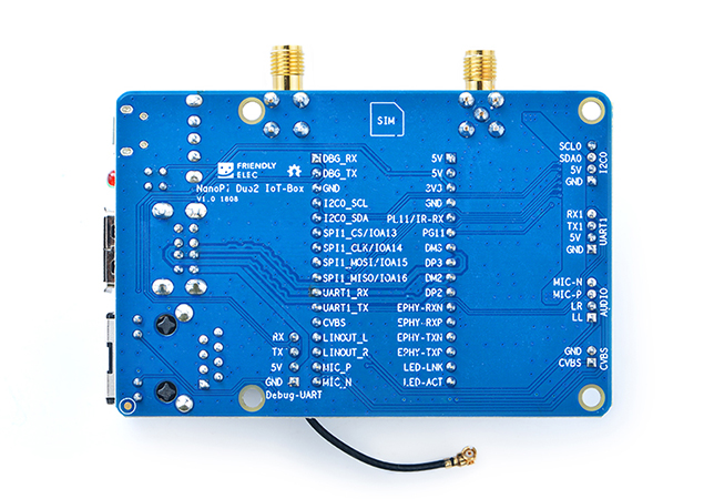
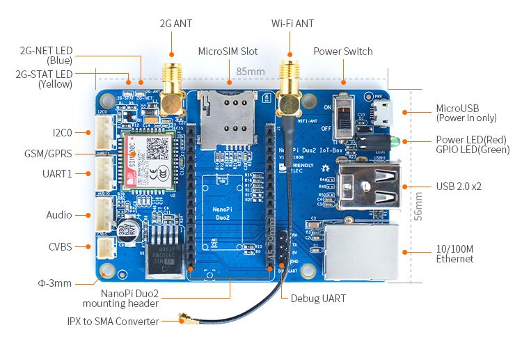
Here is the NanoPi Duo2 IoT-Box's layout. Its pins' remarks are printed on the board.
- NanoPi Duo header Pin Spec
Number# Name Number# Name 1 VDD_5V 17 DEBUG_RX(UART_RXD0)/GPIOA5/PWM0 2 VDD_5V 18 DEBUG_TX(UART_TXD0)/GPIOA4 3 SYS_3.3V 19 GND 4 GND 20 I2C0_SCL/GPIOA11 5 GPIOL11/IR-RX 21 I2C0_SDA/GPIOA12 6 GPIOG11 22 UART3_TX/SPI1_CS/GPIOA13 7 USB-DM3 23 UART3_RX/SPI1_CLK/GPIOA14 8 USB-DP3 24 UART3_CTS/SPI1_MISO/GPIOA16 9 USB-DM2 25 UART3_RTS/SPI1_MOSI/GPIOA15 10 USB-DP2 26 UART1_RX/GPIOG7 11 EPHY-RXN 27 UART1_TX/GPIOG6 12 EPHY-RXP 28 CVBS 13 EPHY-TXN 29 LINEOUT_L 14 EPHY-TXP 30 LINEOUT_R 15 EPHY-LED-LINK 31 MIC_P 16 EPHY-LED-SPD 32 MIC_N
3 Hardware Setup
The NanoPi Duo2 can be mounted on the NanoPi Duo2 IoT-Box carrier board. You can refer to the following setup to assemble them:
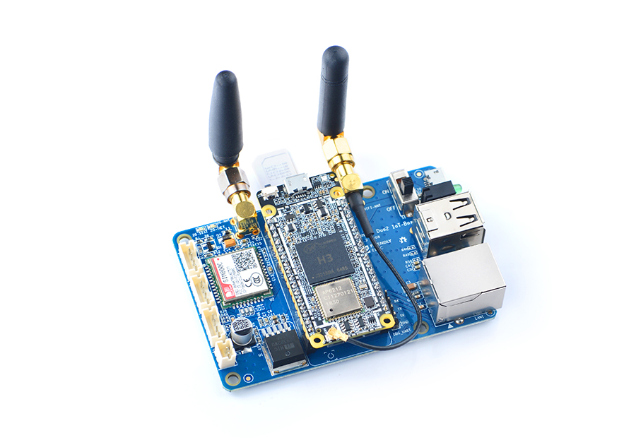
You can connect your NanoPi Duo2 IoT-Box board to a network and external modules such as USB devices
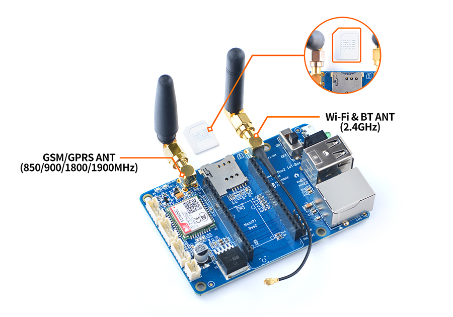
When you use the onboard quad-band GSM/GPRS module you should use an appropriate antenna and this antenna's band is different from an WiFi antenna's band. You can refer to the following setup:
4 Applications
4.1 Work with GSM/GPRS Module
Insert a SIM card and connect a GSM/GPRS antenna to the board:
4.2 Work with USB Host
You can connect a USB device e.g. Matrix - LCD2USB to the NanoPi Duo2 IoT-Box board as follows:
连接Matrix - LCD2USB
4.3 Work with Audio Input & Output
1、可使用以下命令录音:
arecord -D hw:0,0 -f cd test.wav
运行效果如下:
![]()
2、可使用以下命令播放音频文件,例如播放/root/Music/test.wav
aplay /root/Music/test.wav
运行效果如下:

可以使用alsamixer工具调节播放音乐的音量
5 相关资料
- [Schematic](Schematic_NanoPi Duo2 IoT-Box.pdf)
- [Dimension](Dimension_NanoPi Duo2 IoT-Box(dxf))
- [Manual](SIM800_Series_AT_Command_Manual_V1.10.pdf)
