NanoPC-T3 Plus
From FriendlyELEC WiKi
Contents
1 Introduction


- The NanoPC-T3(2GB) octa-core single board computer is designed and developed by FriendlyELEC for professional and enterprise users. It uses the Samsung Octa-Core Cortex-A53 S5P6818 SoC. Compared to the FriendlyELEC NanoPC-T2 the NanoPC-T3(2GB) not only has all the T2’s interfaces and ports but also has a more powerful SoC. Its dynamic frequency scales from 400M up to 1.4GHz. The NanoPC-T3(2GB) has 16G eMMC onboard, audio jack, video input/output interfaces, built-in WiFi, Bluetooth and Gbps Ethernet port. In addition the NanoPC-T3(2GB) has power management, on board porcelain antenna and serial debug port. To avoid overheat issues the NanoPC-T3(2GB) has a heat sink with mounting holes.
- The NanoPC-T3(2GB) has two camera interfaces: a DVP camera interface and a MIPI-CSI interface, and four video interfaces: HDMI 1.4A, LVDS, parallel RGB-LCD interface and MIPI-DSI interface. It supports RTC and has RTC interface pins. It has four USB ports with three being type A ports and one being 2.54mm pitch pin-headers.
- The NanoPC-T3(2GB) supports muitple OS systems e.g. Android5.1, Debian and UbuntoCore+Qt. It is an open source project with rich interfaces and ports. It is born a choice for professional and enterprise users.
2 Hardware Spec
- SoC: Samsung S5P6818 Octa-Core Cortex-A53, 400M Hz - 1.4G Hz
- PMU Power Management: Implemented by a Cortex-M0 MCU, support software power-off, sleep and wakeup functions
- System Memory: 2GB 32bit DDR3 RAM
- SD Storage: 1 x microSD Card Socket
- Ethernet: Gbit Ethernet(RTL8211E)
- WiFi: 802.11b/g/n
- Bluetooth: 4.0 dual mode
- Antenna: Porcelain Antenna IPX Interface
- eMMC: 16GB
- Video Input: DVP Camera/MIPI-CSI (two camera interfaces)
- Video Output: HDMI Type-A / LVDS / Parallel RGB-LCD / MIPI-DSI (four video output interfaces)
- Audio: 3.5 mm audio jack / via HDMI
- Microphone: onboard Microphone
- USB Host: 4 x USB 2.0 Host, three type A ports and one 2.54 mm pitch pin-headers
- MicroUSB: 1 x MicroUSB 2.0 Client, Type A
- LCD Interface: 0.5mm pitch 45 pin FPC seat, full color RGB 8-8-8
- HDMI: 1.4A Type A, 1080P
- DVP Camera: 0.5mm pitch 24 pin FPC seat
- GPIO: 2.54 mm pitch 30 pin-header
- I2S/USB: 2.54 mm pitch 14 pin-header
- Serial Debug Port: 2.54mm pitch 4-pin-header
- User Key: power, Reset, boot selection
- LED: 1 x power LED and 1 x system LED
- Other Resources: CPU’s internal TMU
- RTC Battery: RTC Battery Seat
- Heat Sink: 1 x Heat Sink with mounting holes
- Power: DC 5V/3A
- PCB: Six Layer
- Dimension: 100 mm x 64 mm
- Working Temperature: -40℃ to 80℃
- OS/Software: uboot, Android and Debian
3 Diagram, Layout and Dimension
3.1 Layout

- 30Pin GPIO Pin Spec
Pin# Name Pin# Name 1 SYS_3.3V 2 DGND 3 UART2_TX/GPIOD20 4 UART2_RX/GPIOD16 5 I2C0_SCL 6 I2C0_SDA 7 SPI0_MOSI/GPIOC31 8 SPI0_MISO/GPIOD0 9 SPI0_CLK/GPIOC29 10 SPI0_CS/GPIOC30 11 UART3_TX/GPIOD21 12 UART3_RX/GPIOD17 13 UART4_TX/GPIOB29 14 UART4_RX/GPIOB28 15 UART5_TX/GPIOB31 16 UART5_RX/GPIOB30 17 GPIOC4 18 GPIOC7 19 GPIOC8 20 GPIOC24 21 GPIOC28 22 GPIOB26 23 GPIOD1/PWM0 24 GPIOD8/PPM 25 GPIOC13/PWM1 26 AliveGPIO3 27 GPIOC14/PWM2 28 AliveGPIO5 29 VDD_5V_OUT 30 DGND
- 14Pin I2S/USB Pin Spec
Pin# Name Pin# Name 1 VDD_5V 2 VDD_5V 3 USB_DM2 4 LED1 5 USB_DP2 6 I2S_SDIN1 7 DGND 8 I2S_SDOUT1 9 PWRKEY 10 I2S_MCLK1 11 NRESETIN 12 I2S_BCLK1 13 DGND 14 I2S_LRCK1
- DVP Camera Interface Pin Spec
Pin# Name 1, 2 SYS_3.3V 7,9,13,15,24 DGND 3 I2C0_SCL 4 I2C0_SDA 5 GPIOB14 6 GPIOB16 8 GPIOC13/PWM1 10 NC 11 VSYNC 12 HREF 14 PCLK 16-23 Data bit7-0
- LVDS
Pin# Name 1 VDD_5V_OUT 2 VDD_5V_OUT 3 VDD_5V_OUT 4 LVDS_Y0M 5 LVDS_Y0P 6 DGND 7 LVDS_Y1M 8 LVDS_Y1P 9 DGND 10 LVDS_Y2M 11 LVDS_Y2P 12 DGND 13 LVDS_CLKM 14 LVDS_CLKP 15 DGND 16 LVDS_Y3M 17 LVDS_Y3P 18 DGND 19 GPIOC15 20 DGND 21 I2C2_SCL 22 I2C2_SDA 23 GPIOC16 24 DGND
- Debug Port(UART0)
Pin# Name 1 DGND 2 VDD_5V 3 UART_TXD0 4 UART_RXD0
- RGB LCD Interface Pin Spec
Pin# Name Description 1, 2 VDD_5V_OUT 5V Output, it can be used to power LCD modules 11,20,29, 37,38,39,40, 45 DGND Ground 3-10 Blue LSB to MSB RGB blue 12-19 Green LSB to MSB RGB green 21-28 Red LSB to MSB RGB red 30 GPIOB25 available for users 31 GPIOC15 occupied by FriendlyARM one wire technology to recognize LCD models and control backlight and implement resistive touch, not applicable for users 32 XnRSTOUT Form CPU low when system is reset 33 VDEN signal the external LCD that data is valid on the data bus 34 VSYNC vertical synchronization 35 HSYNC horizontal synchronization 36 LCDCLK LCD clock, Pixel frequency 41 I2C2_SCL I2C2 clock signal, for capacitive touch data transmission 42 I2C2_SDA I2C2 data signal, for capacitive touch data transmission 43 GPIOC16 interrupt pin for capacitive touch, used with I2C2 44 NC Not connected
- MIPI-DSI Interface Pin Spec
Pin# Name 1, 2, 3 VDD_5V_OUT 4 DGND 5 I2C2_SDA 6 I2C2_SCL 7 DGND 8 GPIOC16 9 DGND 10 GPIOC1 11 DGND 12 NC 13 nRESETOUT 14, 15 DGND 16 MIPIDSI_DN3 17 MIPIDSI_DP3 18 DGND 19 MIPIDSI_DN2 20 MIPIDSI_DP2 21 DGND 22 MIPIDSI_DN1 23 MIPIDSI_DP1 24 DGND 25 MIPIDSI_DN0 26 MIPIDSI_DP0 27 DGND 28 MIPIDSI_DNCLK 29 MIPIDSI_DPCLK 30 DGND
- MIPI-CSI Interface Pin Spec
Pin# Name 1, 2 SYS_3.3V 3 DGND 4 I2C0_SDA 5 I2C0_SCL 6 DGND 7 SPI2_MOSI/GPIOC12 8 SPI2_MISO/GPIOC11 9 SPI2_CS/GPIOC10 10 SPI2_CLK/GPIOC9 11 DGND 12 GPIOB23 13 GPIOC2 14, 15 DGND 16 MIPICSI_DN3 17 MIPICSI_DP3 18 DGND 19 MIPICSI_DN2 20 MIPICSI_DP2 21 DGND 22 MIPICSI_DN1 23 MIPICSI_DP1 24 DGND 25 MIPICSI_DN0 26 MIPICSI_DP0 27 DGND 28 MIPICSI_DNCLK 29 MIPICSI_DPCLK 30 DGND
- RTC
- 3.35uA@3V
- USB 2.0 Host
- with 1A over current protection
- Notes
- SYS_3.3V: 3.3V power output
- VDD_5V/VDD_5V_OUT: 5V power output
- For more details refer to the document: NanoPC-T3-1709-Schematic.pdf
3.2 Board Dimension

- For more details refer to the document: NanoPC-T3-1709-Drawing(dxf).zip
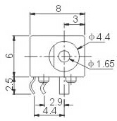
- Power Jack
- DC 4.7~5.6V IN, 4.0*1.7mm Power Jack