Difference between revisions of "NanoPC-T3"
(→制作一张带运行系统的SD卡) |
(→烧写系统到NanoPC-T3的eMMC) |
||
| Line 348: | Line 348: | ||
* Insert this card into your NanoPC-T3's boot slot, press and hold the boot key and power on (with a 5V/2A power source). If the PWR LED is on and LED1 is blinking this indicates your NanoPC-T3 has successfully booted.<br /> | * Insert this card into your NanoPC-T3's boot slot, press and hold the boot key and power on (with a 5V/2A power source). If the PWR LED is on and LED1 is blinking this indicates your NanoPC-T3 has successfully booted.<br /> | ||
| − | ==== | + | ====Boot NanoPC-T3 from eMMC==== |
| − | * | + | * Download RAW Image<br /> |
| − | + | Get the image file: s5p6818-eflasher-sd4g.img.zip and the Windows utility: win32diskimager.rar; | |
| − | * | + | * Flash RAW Image to SD Card<br /> |
| − | + | Insert an SD card(at least 4G) into a Windows PC and run the win32diskimager utility as administrator. On the utility's main window select your SD card's drive, the wanted image file and click on "write" to start flashing the SD card | |
| − | * | + | * Prepare RAW image |
| − | + | Go to this link [http://wiki.friendlyarm.com/wiki/nanopi2/download/] to download Android and Debian image files(System-image-files-for-eMMC). After download untar the ".tgz" ball and copy the files to your SD card. | |
::{| class="wikitable" | ::{| class="wikitable" | ||
|- | |- | ||
Revision as of 10:00, 27 April 2016
Contents
1 Introduction


- The NanoPC-T3 octa-core single board computer is designed and developed by FriendlyARM for professional and enterprise users. It uses the Samsung Octa-Core Cortex-A53 S5P6818 SoC. Compared to the FriendlyARM NanoPC-T2 the NanoPC-T3 not only has all the T2’s interfaces and ports but also has a more powerful SoC. Its dynamic frequency scales from 400M up to 1.4GHz. The NanoPC-T3 has 8G eMMC onboard, audio jack, video input/output interfaces, built-in WiFi, Bluetooth and Gbps Ethernet port. In addition the NanoPC-T3 has power management, on board porcelain antenna and serial debug port. To avoid overheat issues the NanoPC-T3 has a heat sink with mounting holes.
- The NanoPC-T3 has two camera interfaces: a DVP camera interface and a MIPI-CSI interface, and four video interfaces: HDMI 1.4A, LVDS, parallel RGB-LCD interface and MIPI-DSI interface. It supports RTC and has RTC interface pins. It has four USB ports with two being type A ports and two being 2.54mm pitch pin-headers.
- The NanoPC-T3 supports muitple OS systems e.g. Android5.1, Debian and UbuntoCore+Qt. It is an open source project with rich interfaces and ports. It is born a choice for professional and enterprise users.
2 Features
- SoC: Samsung S5P6818 Octa-Core Cortex-A53, 400M Hz - 1.4G Hz
- Power Management Unit: AXP228 PMU, it supports software power-off and wake-up.
- System Memory: 1GB/2GB 32bit DDR3 RAM
- Storage: 1 x SD Card Socket
- Ethernet: Gbit Ethernet(RTL8211E)
- WiFi: 802.11b/g/n
- Bluetooth: 4.0 dual mode
- Antenna: Porcelain Antenna IPX Interface
- eMMC: 8GB
- Video Input: DVP Camera/MIPI-CSI (two camera interfaces)
- Video Output: HDMI Type-A / LVDS / Parallel RGB-LCD / MIPI-DSI (four video output interfaces)
- Audio: 3.5 mm audio jack / via HDMI
- Microphone: onboard Microphone
- USB Host: 4 x USB 2.0 Host, two type A ports and two 2.54 mm pitch pin-headers
- MicroUSB: 1 x MicroUSB 2.0 Client, Type A
- LCD Interface: 0.5mm pitch 45 pin FPC seat, full color RGB 8-8-8
- HDMI: 1.4A Type A, 1080P
- DVP Camera: 0.5mm pitch 24 pin FPC seat
- GPIO: 2.54 mm pitch 30 pin-header
- Serial Debug Port: 2.54mm pitch 4-pin-header
- User Key: K1 (power), Reset
- LED: 1 x power LED and 2 x GPIO LED
- Other Resources: CPU’s internal TMU
- RTC Battery: RTC Battery Seat
- Heat Sink: 1 x Heat Sink with mounting holes
- Power: DC 5V/2A
- PCB: Six Layer
- Dimension: 100 mm x 60 mm
- OS/Software: uboot, Android and Debian
3 Diagram, Layout and Dimension
3.1 Layout

- 30Pin GPIO Pin Spec
Pin# Name Pin# Name 1 SYS_3.3V 2 DGND 3 UART2_TX/GPIOD20 4 UART2_RX/GPIOD16 5 I2C0_SCL 6 I2C0_SDA 7 SPI0_MOSI/GPIOC31 8 SPI0_MISO/GPIOD0 9 SPI0_CLK/GPIOC29 10 SPI0_CS/GPIOC30 11 UART3_TX/GPIOD21 12 UART3_RX/GPIOD17 13 UART4_TX/GPIOB29 14 UART4_RX/GPIOB28 15 UART5_TX/GPIOB31 16 UART5_RX/GPIOB30 17 GPIOC4 18 GPIOC7 19 GPIOC8 20 GPIOC24 21 GPIOC28 22 GPIOB26 23 GPIOD1/PWM0 24 GPIOD8/PPM 25 GPIOC13/PWM1 26 AliveGPIO3 27 GPIOC14/PWM2 28 AliveGPIO5 29 VDD_5V 30 DGND
- 20Pin LVDS Interface Pin Spec
Pin# Name Pin# Name 1 SYS_3.3V 2 SYS_3.3V 3 GPIOC16 4 GPIOB18 5 DGND 6 DGND 7 LVDS_D0- 8 LVDS_D0+ 9 LVDS_D1- 10 LVDS_D1+ 11 LVDS_D2- 12 LVDS_D2+ 13 DGND 14 DGND 15 LVDS_CLK- 16 LVDS_CLK+ 17 LVDS_D3- 18 LVDS_D3+ 19 I2C2_SCL 20 I2C2_SDA
- DVP Camera Interface Pin Spec
Pin# Name 1, 2 SYS_3.3V 7,9,13,15,24 DGND 3 I2C0_SCL 4 I2C0_SDA 5 GPIOB14 6 GPIOB16 8,10 NC 11 VSYNC 12 HREF 14 PCLK 16-23 Data bit7-0
- RGB LCD Interface Pin Spec
Pin# Name Description 1, 2 VDD_5V 5V Output, it can be used to power LCD modules 11,20,29, 37,38,39,40, 45 DGND Ground 3-10 Blue LSB to MSB RGB blue 12-19 Green LSB to MSB RGB green 21-28 Red LSB to MSB RGB red 30 GPIOB25 available for users 31 GPIOC15 occupied by FriendlyARM one wire technology to recognize LCD models and control backlight and implement resistive touch, not applicable for users 32 XnRSTOUT Form CPU low when system is reset 33 VDEN signal the external LCD that data is valid on the data bus 34 VSYNC vertical synchronization 35 HSYNC horizontal synchronization 36 LCDCLK LCD clock, Pixel frequency 41 I2C2_SCL I2C2 clock signal, for capacitive touch data transmission 42 I2C2_SDA I2C2 data signal, for capacitive touch data transmission 43 GPIOC16 interrupt pin for capacitive touch, used with I2C2 44 NC Not connected
- MIPI-DSI Interface Pin Spec
Pin# Name 1, 2, 3 VDD_5V 4 DGND 5 I2C2_SDA 6 I2C2_SCL 7 DGND 8 GPIOC0 9 DGND 10 GPIOC1 11 DGND 12 GPIOA28 13 nRESETOUT 14, 15 DGND 16 MIPIDSI_DN3 17 MIPIDSI_DP3 18 DGND 19 MIPIDSI_DN2 20 MIPIDSI_DP2 21 DGND 22 MIPIDSI_DN1 23 MIPIDSI_DP1 24 DGND 25 MIPIDSI_DN0 26 MIPIDSI_DP0 27 DGND 28 MIPIDSI_DNCLK 29 MIPIDSI_DPCLK 30 DGND
- MIPI-CSI Interface Pin Spec
Pin# Name 1, 2 SYS_3.3V 3 DGND 4 I2C0_SDA 5 I2C0_SCL 6 DGND 7 SPI2_MOSI/GPIOC12 8 SPI2_MISO/GPIOC11 9 SPI2_CS/GPIOC10 10 SPI2_CLK/GPIOC9 11 DGND 12 GPIOB9 13 GPIOC2 14, 15 DGND 16 MIPICSI_DN3 17 MIPICSI_DP3 18 DGND 19 MIPICSI_DN2 20 MIPICSI_DP2 21 DGND 22 MIPICSI_DN1 23 MIPICSI_DP1 24 DGND 25 MIPICSI_DN0 26 MIPICSI_DP0 27 DGND 28 MIPICSI_DNCLK 29 MIPICSI_DPCLK 30 DGND
- Notes
- SYS_3.3V: 3.3V power output
- VDD_5V: 5V power input/output. The input range is 4.7V ~ 5.6V
- For more details refer to the document: NanoPC-T3 Schematic
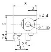
3.2 Board Dimension

- For more details refer to the document: NanoPC-T3-Dimensions(dxf)
- Power Jack
- DC 4.7~5.6V IN, 4.0*1.7mm Power Jack

4 Notes in Hardware Design
4.1 EEPROM
- The board has an EEPROM(model: 24AA025E48T-I/OT) with a unique MAC. This EEPROM is connected to I2C0 and its address is 0x51 therefore some EEPROM chips cannot be connected to I2C0 which will cause conflicts of addresses.
- In our tests these EEPROM chips cannot be connected to I2C0: 24C04, 24C08 and 24C16. There chips which we tested can be connected to I2C0: 24C01, 24C02 and 24C256
- For more details about EEPROM address issues refer to http://www.onsemi.com/pub_link/Collateral/CAT24C01-D.PDF
5 Get Started
5.1 Essentials You Need
Before starting to use your NanoPC-T3 get the following items ready
- NanoPC-T3
- SD Card: Class 10 or Above, minimum 8GB SDHC
- A DC 5V/2A power is a must
- HDMI monitor or LCD
- USB keyboard, mouse and possible a USB hub(or a TTL to serial board)
- A host computer running Ubuntu 14.04 64 bit system
5.2 Make an Installation SD Card
5.2.1 Boot NanoPC-T3 from SD Card
Get the following files from here to download necessary files:
- Get a 4G SDHC card and backup its data if necessary
For LCD or HDMI output use the following files: s5p6818-debian-sd4g-20160426.img Debian image files s5p6818-android-sd4g-20160426.img Android image files s5p6818-core-qte-sd4g-20160426.img Ubuntu Core + QT image files Flash Utility: win32diskimager.rar Windows utility. Under Linux users can use "dd"
- Uncompress these files. Insert an SD card(at least 4G) into a Windows PC and run the win32diskimager utility as administrator. On the utility's main window select your SD card's drive, the wanted image file and click on "write" to start flashing the SD card.
- Insert this card into your NanoPC-T3's boot slot, press and hold the boot key and power on (with a 5V/2A power source). If the PWR LED is on and LED1 is blinking this indicates your NanoPC-T3 has successfully booted.
5.2.2 Boot NanoPC-T3 from eMMC
- Download RAW Image
Get the image file: s5p6818-eflasher-sd4g.img.zip and the Windows utility: win32diskimager.rar;
- Flash RAW Image to SD Card
Insert an SD card(at least 4G) into a Windows PC and run the win32diskimager utility as administrator. On the utility's main window select your SD card's drive, the wanted image file and click on "write" to start flashing the SD card
- Prepare RAW image
Go to this link [1] to download Android and Debian image files(System-image-files-for-eMMC). After download untar the ".tgz" ball and copy the files to your SD card.
OS Image Files Copy to... Android 5.1 android-lollipop-images.tgz
android-lollipop-images.tgz.hash.md5boot.img
system.img
userdata.img
cache.img
partmap.txt
images\android Debian (Jessie) debian-jessie-images.tgz
debian-jessie-images.tgz.hash.md5boot.img
rootfs.img
partmap.txt
images\debian Ubuntu Core + QT core-qte-images.tgz
core-qte-images.tgz.hash.md5boot.img
rootfs.img
partmap.txt
images\core-qte
- 指定需要烧写的OS
SD卡上配置文件 images\FriendlyARM.ini 缺省是将烧写 Android,如果要烧写Debian,则只需要编辑此文件:
OS = Debian
即可,其中配置文件中”#” 开始行的是注释。
- 烧写到NanoPC-T3的eMMC
将制作好的SD卡插入NanoPC-T3,连接HDMI或LCD, 按住网口旁边标住有boot的按键,拨动电源开关,板子则会自动开始烧写,你可以通过HDMI或LCD上的显示来查看烧写状态,如果看到以下内容即表示成功,否则失败。
Android is fused successfully.
All done.
烧写成功完成后,必须按复位键或重新加电, 即可从eMMC启动。
你还可以根据LED来确定烧写状态,以下是LED状态检查表:
LED闪烁状态 系统状态 LED1心跳模式闪 (连续快闪2次)
LED2灭加电后正常启动的状态
如果没有进行烧写则会保持为此状态LED1和LED2交替闪烁 (0.3s) 正在烧写系统 LED1和LED2交替的呼吸效果 (1.2s) 烧写成功 LED1和LED2同时快闪 烧写失败
5.2.3 在Linux Desktop下通过脚本制作
- 1) 将SD卡插入Ubuntu的电脑,用以下命令查看你的SD卡设备名
dmesg | tail
当dmesg输出类拟信息 sdc: sdc1 sdc2时,则表示SD卡对应的设备名为 /dev/sdc,也通过用命令cat /proc/partitions来查看。
- 2) 下载Linux下的制作脚本
git clone https://github.com/friendlyarm/sd-fuse_nanopi3.git
cd sd-fuse_nanopi3
- 3) 以下是制作启动Android的SD卡的方法
su
./fusing.sh /dev/sdx
(注:/dev/sdx请替换为实际的SD卡设备文件名)
制作包中未包含Android和Debian的烧写文件,第一次使用时会提示需要下载,输入Y下载,N或10秒未输入则取消。
- 4) 以下是制作启动Debian的SD卡的方法
./fusing.sh /dev/sdx debian
5.2.4 关于LCD/HDMI分辨率
系统启动时uboot会自动识别LCD,成功则会设置为该LCD的显示分辨率,失败则缺省会设置为HDMI 720P模式。
如果要修改LCD的显示分辨率,可以直接修改内核中的文件 arch/arm/plat-s5p6818/nanopi3/lcds.c , 然后重新编译内核并更新即可。
对于HDMI的显示模式,Android则是会通过EDID获得HDMI设备如电视机所支持的显示模式,然后自动选择一个合适的分辨率。如果使用的是Debian,则缺省是720P,可通过修改内核配置来切换为1080P。
5.3 在电脑上修改SD卡上的系统
如果你想在运行系统之前,先对系统做一些修改,可以参看本节内容,否则可以跳过本节。
将制作好SD卡插入一台运行Linux的电脑,可以挂载SD卡上的boot和rootfs等分区,对分区内容进行修改,通过在以下情况下你需要进行这些操作:
1) 你想更改Kernel Command Line参数,则可以通过sd-fuse_nanopi3/tools目录下的fw_setenv工具来操作。
查看当前的Command Line:
cd sd-fuse_nanopi3/tools
./fw_printenv /dev/sdc | grep bootargs
目前的Android 5.1.1_r6启用了SELinux,缺省模式是enforcing,你可以通过Command Line来修改它,例如:
./fw_setenv /dev/sdc bootargs XXX androidboot.selinux=permissive
即可修改为permissive模式,其中上面的XXX需要替换成原来的bootargs值。
2) 更新内核
新版本的uboot在启动时如果识别到LCD,将读取SD卡boot分区的uImage,否则将读取uImage.hdmi。
对于Android来说是同一个文件,因此直接使用新编译的uImage来替换SD卡boot分区下的文件即可。
对于Debian来说,这2个文件是不相同的,使用新编译的支持LCD的uImage直接替换SD卡boot分区的文件,如果是支持HDMI的内核,则替换uImage.hdmi。
5.4 运行Android或Debian
- 将制作好SD卡插入NanoPC-T3,连接HDMI,按住靠近网口的boot按键,最后接电源(5V 2A)拨动开关,NanoPC-T3会从SD卡启动。你可以看到板上PWR灯常亮,LED1灯闪烁,这说明系统已经开始启动了,同时电视上也将能看到系统启动的画面。
1)要在电视上进行操作,你需要连接USB鼠标和键盘;如果你选购了LCD配件,则可以直接使用LCD上面的触摸屏进行操作。
2)如果您需要进行内核开发,你最好选购一个串口配件,连接了串口,则可以通过终端对NanoPC-T3进行操作。
- 以下是串口的接法。接上串口,即可调试:

- 如果提示输入密码,Debian的root用户的默认密码是两个字母fa。
5.5 通过VNC和ssh登录Debian
如果你是祼板运行系统(既没有连接LCD也没有连接HDMI),并且烧写了带 -wifiap.img 后辍的固件,你可以使用手机,或者有无线网卡的电脑连接到NanoPC-T3开放的 nanopi2-wifiap 无线热点(默认密码是123456789),连接成功后,无论是手机还是电脑,你可以到这里下载并安装一个名为VNC Viewer的软件,用VNC连接到NanoPC-T3,NanoPC-T3在使用VNC时的连接地址和端口为:192.168.8.1:5901,默认密码为:fa123456,以下是在iPhone上用VNC登录NanoPC-T2的画面:

你也可以通过 ssh -l root 192.168.8.1 命令在终端上登录,默认的root用户密码是 fa。
为了保证ssh的流畅,我们用以下命令关闭wifi的省电模式:
iwconfig wlan0 power off
6 Debian系统的使用
6.1 连接有线网络
- NanoPC-T3支持千兆网络,Debian或者Android系统在启动前,只要接上网线,系统启动后则会自动分配IP地址,不需要额外去配置。
6.2 连接无线网络
用vi或在图形界面下用gedit编辑文件 /etc/wpa_supplicant/wpa_supplicant.conf, 在文件末尾填入路由器信息如下所示:
network={
        ssid="YourWiFiESSID"
        psk="YourWiFiPassword"
}
其中,YourWiFiESSID和YourWiFiPassword请替换成你要连接的无线AP名称和密码。
保存退出后,执行以下命令即可连接WiFi:
ifdown wlan0
ifup wlan0
如果你的WiFi密码中有特殊字符,或者你不希望明文存放密码,你可以使用wpa_passphrase命令为WiFi密码生成一个密钥(psk),用密钥来代替密码 ,在命令行下,可输入以下命令生成密钥:
wpa_passphrase YourWiFiESSID
在提示输入密码时,输入你的WiFi密码,再打开 /etc/wpa_supplicant/wpa_supplicant.conf 文件你会发现密钥已经被更新,你可以删除明文的密码了。
如果你的WiFi当前处于无线热点模式,你需要先退出该模式方可连接到路由器,使用以下命令退出无线热点模式:
su
turn-wifi-into-apmode no
6.3 配置Wi-Fi无线热点
可以通过以下命令,将Wi-Fi切换至无线热点模式:
turn-wifi-into-apmode yes按提示重启即可,默认的热点名称为 nanopi2-wifiap,密码为123456789。
现在,你可以在电脑上搜索并连接nanopi2-wifiap这个无线热点,连接成功后,可以通过ssh到192.168.8.1这个地址来登录NanoPC-T3:
ssh root@192.168.8.1
在提示输入密码时,输入预设的密码fa,即可登入。
为了保证ssh的流畅,我们用以下命令关闭wifi的省电模式:
iwconfig wlan0 power off
WiFi工作模式可通过以下命令查询:
cat /sys/module/bcmdhd/parameters/op_mode
输出为数字2则表示当前处于无线热点模式,要切换回普通的Station模式,输入如下命令:
turn-wifi-into-apmode no
6.4 使用蓝牙传输
点击右下角的蓝牙图标,会弹出一个操作菜单,其中,
Make discoverable菜单项是打开NanoPC-T3蓝牙的可发现属性,这样其他设备(例如手机)就可以搜索到NanoPC-T3并进行配对了;
Devices... 菜单项可以打开搜索界面,主动搜索周边的蓝牙设备(注:需要这个设备先打开可发现属性);
Send Files to Device...菜单项则可以通过蓝牙发送文件到已配对的指定设备上。
6.5 安装Debian软件包
我们提供的是标准的Debian jessie系统,你可以使用apt-get等命令来安装软件包,如果板子是首次运行,需要先用以下命令更新软件包列表:
apt-get update然后就可以安装软件包了,例如要安装ftp服务器,使用以下命令:
apt-get install vsftpd如果软件包下载速度不理想,你可以编辑 /etc/apt/sources.list 更换一个更快的源服务器,这个网址[2]有一份完整的源镜像服务器列表,注意要选用一个带armhf架构的。
7 如何编译系统
7.1 安装交叉编译器
首先下载并解压编译器:
git clone https://github.com/friendlyarm/prebuilts.git
sudo mkdir -p /opt/FriendlyARM/toolchain
sudo tar xf prebuilts/gcc-x64/arm-cortexa9-linux-gnueabihf-4.9.3.tar.xz -C /opt/FriendlyARM/toolchain/
然后将编译器的路径加入到PATH中,用vi编辑vi ~/.bashrc,在末尾加入以下内容:
export PATH=/opt/FriendlyARM/toolchain/4.9.3/bin:$PATH
export GCC_COLORS=auto
执行一下~/.bashrc脚本让设置立即在当前shell窗口中生效,注意"."后面有个空格:
. ~/.bashrc这个编译器是64位的,不能在32位的Linux系统上运行,安装完成后,你可以快速的验证是否安装成功:
arm-linux-gcc -v
Using built-in specs.
COLLECT_GCC=arm-linux-gcc
COLLECT_LTO_WRAPPER=/opt/FriendlyARM/toolchain/4.9.3/libexec/gcc/arm-cortexa9-linux-gnueabihf/4.9.3/lto-wrapper
Target: arm-cortexa9-linux-gnueabihf
Configured with: /work/toolchain/build/src/gcc-4.9.3/configure --build=x86_64-build_pc-linux-gnu
--host=x86_64-build_pc-linux-gnu --target=arm-cortexa9-linux-gnueabihf --prefix=/opt/FriendlyARM/toolchain/4.9.3
--with-sysroot=/opt/FriendlyARM/toolchain/4.9.3/arm-cortexa9-linux-gnueabihf/sys-root --enable-languages=c,c++
--with-arch=armv7-a --with-tune=cortex-a9 --with-fpu=vfpv3 --with-float=hard
...
Thread model: posix
gcc version 4.9.3 (ctng-1.21.0-229g-FA)
7.2 编译U-Boot
下载U-Boot源代码并编译,注意分支是nanopi2-lollipop-mr1:
git clone https://github.com/friendlyarm/uboot_nanopi2.git
cd uboot_nanopi2
git checkout nanopi2-lollipop-mr1
make s5p6818_nanopi3_config
make CROSS_COMPILE=arm-linux-
编译成功结束后您将获得u-boot.bin,您可以通过fastboot来更新正在运行的NanoPC-T3板上SD的U-Boot,方法如下:
1) 在电脑上先用命令 sudo apt-get install android-tools-fastboot 安装 fastboot 工具;
2) 用串口配件连接NanoPC-T3和电脑,在上电启动的2秒内,在串口终端上按下回车,进入 u-boot 的命令行模式;
3) 在u-boot 命令行模式下输入命令 fastboot 回车,进入 fastboot 模式;
4) 用microUSB线连接NanoPC-T3和电脑,在电脑上输入以下命令烧写u-boot.bin:
fastboot flash bootloader u-boot.bin
注意:您不能直接使用dd来更新SD卡,否则有可能会导致无法正常启动。
7.3 准备mkimage
编译内核需要用到U-Boot中的工具mkimage,因此,在编译内核uImage前,您需要保证您的主机环境可以成功运行它。
你可以直接使用命令 sudo apt-get install u-boot-tools 来安装,也可以自己编译并安装:
cd uboot_nanopi2
make CROSS_COMPILE=arm-linux- tools
sudo mkdir -p /usr/local/sbin && sudo cp -v tools/mkimage /usr/local/sbin
7.4 编译Linux kernel
7.4.1 编译内核
- 下载内核源代码
git clone https://github.com/friendlyarm/linux-3.4.y.git
cd linux-3.4.y
git checkout nanopi2-lollipop-mr1
NanoPC-T2内核所属的分支是nanopi2-lollipop-mr1,在开始编译前先切换分支。
- 编译Android内核
make nanopi3_android_defconfig
touch .scmversion
make uImage
- 编译Debian内核
make nanopi3_linux_defconfig
touch .scmversion
make uImage
编译成功结束后,新生成的内核烧写文件为 arch/arm/boot/uImage,此内核支持HDMI 720p输出,用于替换掉SD卡boot分区下的uImage.hdmi。
如果要支持HDMI 1080p,则需要修改内核配置:
touch .scmversion
make nanopi3_linux_defconfig
make menuconfig
  Device Drivers -->
    Graphics support -->
      Nexell Graphics -->
        [ ] LCD
        [*] HDMI
        (0)   Display In  [0=Display 0, 1=Display 1]
              Resolution (1920 * 1080p)  --->
make uImage
启用LCD,同时取消HDMI,然后退出并保存配置,编译后即可获得支持LCD显示的uImage,用于替换SD卡boot分区下的uImage。
7.4.2 如何使用新编译的内核
- 更新SD卡上的内核
如果您是使用SD卡启动Android,则在PC上复制为Android编译的uImage到SD卡的boot分区(即分区1,设备是/dev/sdX1)即可。
如果您是使用SD卡启动Debian系统,则需要编译好用于HDMI的uImage后替换SD卡boot分区下的uImage.hdmi,然后编译用于LCD的uImage并替换SD卡boot分区下的uImage。
- 更新eMMC上Android的内核
如果只想单独更新eMMC上的内核来测试,则需要先正常启动板,然后mount eMMC的boot分区,使用新编译的uImage来替换原有文件,完成后reboot即可。
从eMMC启动时可通过以下方法来更新内核:
1) 启动完成后,需要手动mount eMMC的boot分区(设备是/dev/mmcblk0p1), 可通过串口在板上操作:
su
mount -t ext4 /dev/block/mmcblk0p1 /mnt/media_rw/sdcard1/
2) 连接USB,在PC端Ubuntu下使用adb push命令复制新编译的uImage到已mount的boot分区下;
adb push uImage /mnt/media_rw/sdcard1/
3) 也可以将编译好的内核复制到SD卡或U盘,然后在板上复制到boot分区下;
4) 更新完成后,输入 reboot 命令重启即可,注意不要直接断电或按Reset键,否则可能会损坏文件。
- 更新eMMC上Debian的内核
从eMMC启动时可通过以下方法来更新内核:
1) 启动完成后,系统通常会自动mount eMMC的boot分区(设备是/dev/mmcblk0p1), 可输入命令mount来查看;
2) 连接网络,使用scp/ftp等方式复制新编译的uImage并替换boot分区下的文件,如果是用于HDMI的内核,则替换uImage.hdmi;
3) 也可以将编译好的内核复制到SD卡或U盘,然后在板止复制到boot分区下;
4) 更新完成后,输入 reboot 命令重启即可,注意不要直接断电或按Reset键,否则可能会损坏文件.
- 使用新的内核来生成boot.img
如果要生成直接烧写eMMC的文件,则需要使用新编译的内核来生成boot.img,然后复制到烧写用的SD卡即可直接烧写到eMMC.
对于Android,将新的uImage复制Android源码的device/friendly-arm/nanopi3/boot/ 下,然后编译Android即可获得新的boot.img .
对于Debian, 则需要使用按以下方法来生成boot.img :
1) 下载debian_nanopi2
git clone https://github.com/friendlyarm/debian_nanopi2.git
2) 复制用于HDMI的uImage到debian_nanopi2/boot/uImage.hdmi, 复制用于LCD的 uImage到debian_nanopi2/boot/uImage ;
3) 生成Debian的 boot.img
cd debian_nanopi2
mkdir rootfs
./build.sh
新的 boot.img 在 debian_nanopi2/sd-fuse_nanopi2/debian 下.
其中命令"mkdir rootfs"只是创建一个空的目录使得build.sh可以运行,因此生成的其它文件比如rootfs.img不能使用。
7.4.3 编译内核模块
Android包含内核模块,位于system分区的 /lib/modules/ 下,如果您有新的内核模块或者内核配置有变化,则需要重新编译。
首先编译内核源代码中的模块:
cd linux-3.4.y
make CROSS_COMPILE=arm-linux- modules
另外有2个内核模块的源代码位于Android源代码中,可使用以下命令来编译:
cd /opt/FriendlyARM/s5p6818/android
./vendor/friendly-arm/build/common/build-modules.sh
其中 “/opt/FriendlyARM/s5p6818/android” 是指Android源代码的TOP目录,使用参数“-h”可查看帮助。
编译成功结束后,会显示生成的内核模块。
7.5 编译Android
- 搭建编译环境
搭建编译Android的环境建议使用64位的Ubuntu 14.04,安装需要的包即可。
sudo apt-get install bison g++-multilib git gperf libxml2-utils make python-networkx zip
sudo apt-get install flex libncurses5-dev zlib1g-dev gawk minicom
更多说明可查看 https://source.android.com/source/initializing.html 。
- 下载源代码
Android源代码的下载需要使用repo,其安装和使用请查看 https://source.android.com/source/downloading.html 。
mkdir android && cd android
repo init -u https://github.com/friendlyarm/android_manifest.git -b nanopi3-lollipop-mr1
repo sync
其中“android”是指工作目录。
- 编译系统
source build/envsetup.sh
lunch aosp_nanopi3-userdebug
make -j8
编译成功完成后,目录 out/target/product/nanopi3/ 下包含可用于烧写的image文件。
filename partition Description boot.img boot - cache.img cache - userdata.img userdata - system.img system - partmap.txt - 分区描述文件
- 烧写到SD卡
如果是采用SD卡启动Android,可复制编译生成的image文件到sd-fuse_nanopi3/android/ 下,使用脚本即可烧到到SD卡,具体请查看#在Linux Desktop下通过脚本制作。
- 烧写到eMMC
成功编译Android后,可过2种方式烧写到eMMC,分别如下:
1) fastboot: 板子从eMMC启动后通过串口快速按任意键进入uboot命令行模式,输入命令fastboot即可启动此方式。
连接USB线,然后PC端输入以下命令:
cd out/target/product/nanopi3
sudo fastboot flash boot boot.img
sudo fastboot flash cache cache.img
sudo fastboot flash userdata userdata.img
sudo fastboot flash system system.img
sudo fastboot reboot
2) 使用SD卡烧写
复制out/target/product/nanopi3下的boot.img, cache.img, userdata.img, system.img, partmap.txt到烧写用SD卡的images/android下,再次烧写即可。
8 源代码和固件下载链接
- 烧写固件下载链接:[]
- 源代码下载链接:[3]
9 资源链接
- 原理图: NanoPC-T3 Schematic
- PCB详细尺寸: NanoPC-T3-Dimensions(dxf)