Difference between revisions of "Matrix - LED"
(→Update Log) |
|||
| (15 intermediate revisions by 2 users not shown) | |||
| Line 1: | Line 1: | ||
[[Matrix - LED/zh|查看中文]] | [[Matrix - LED/zh|查看中文]] | ||
| + | |||
| + | ==Introduction== | ||
| + | [[File:led01.png|thumb|LED]] | ||
| + | [[File:led02.png|thumb|LED]] | ||
| + | [[File:led03.png|thumb|LED]] | ||
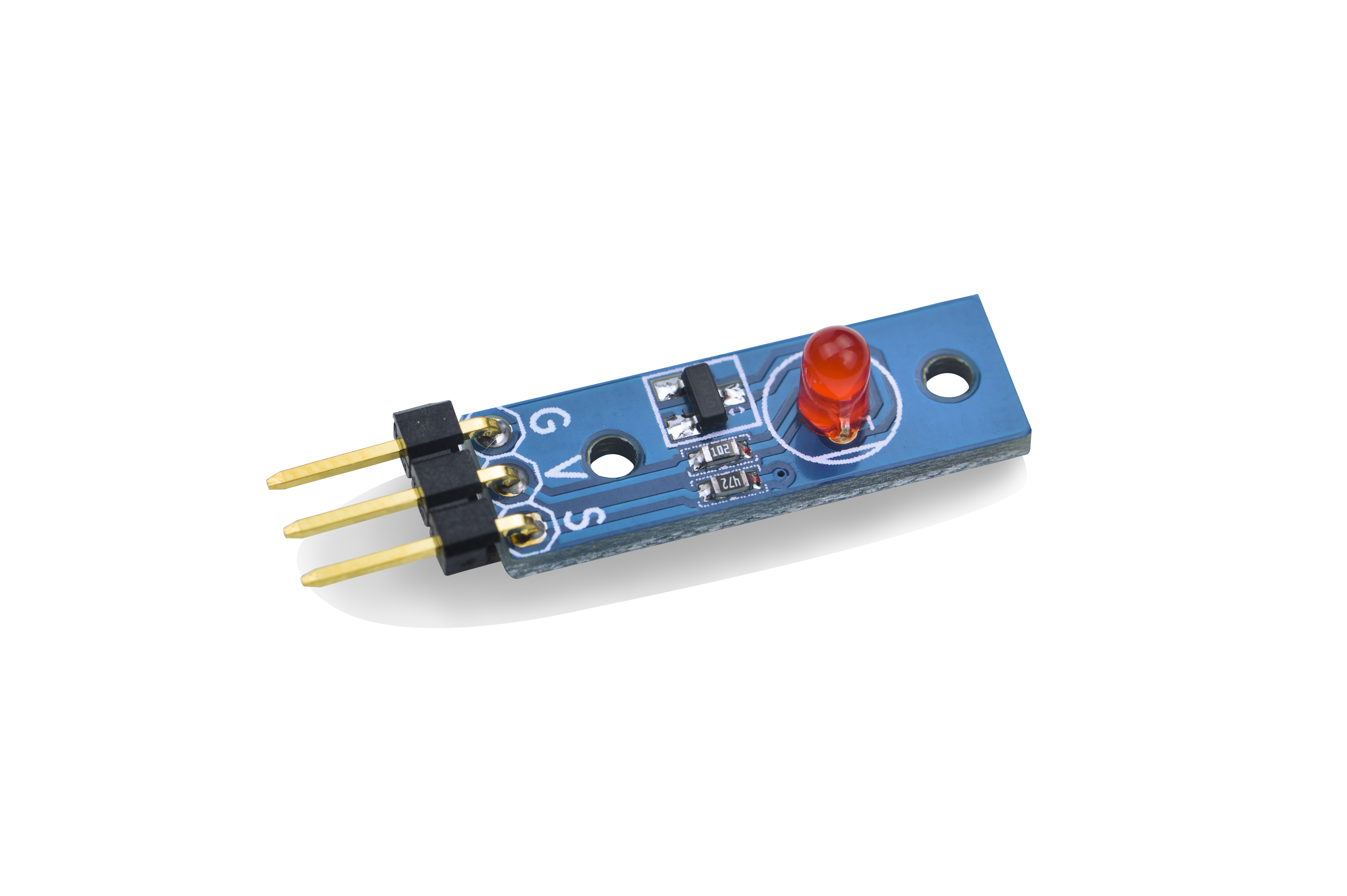
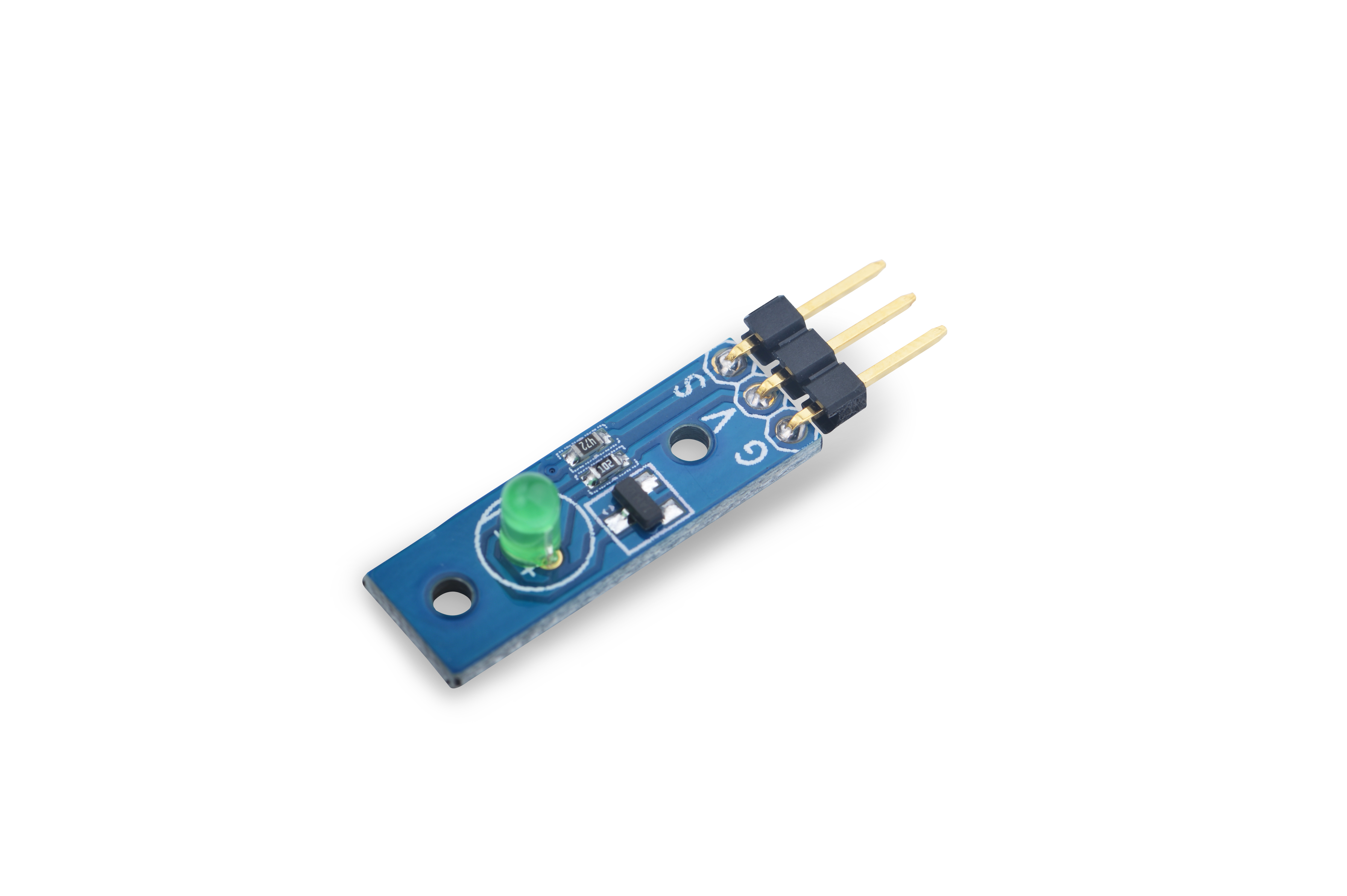
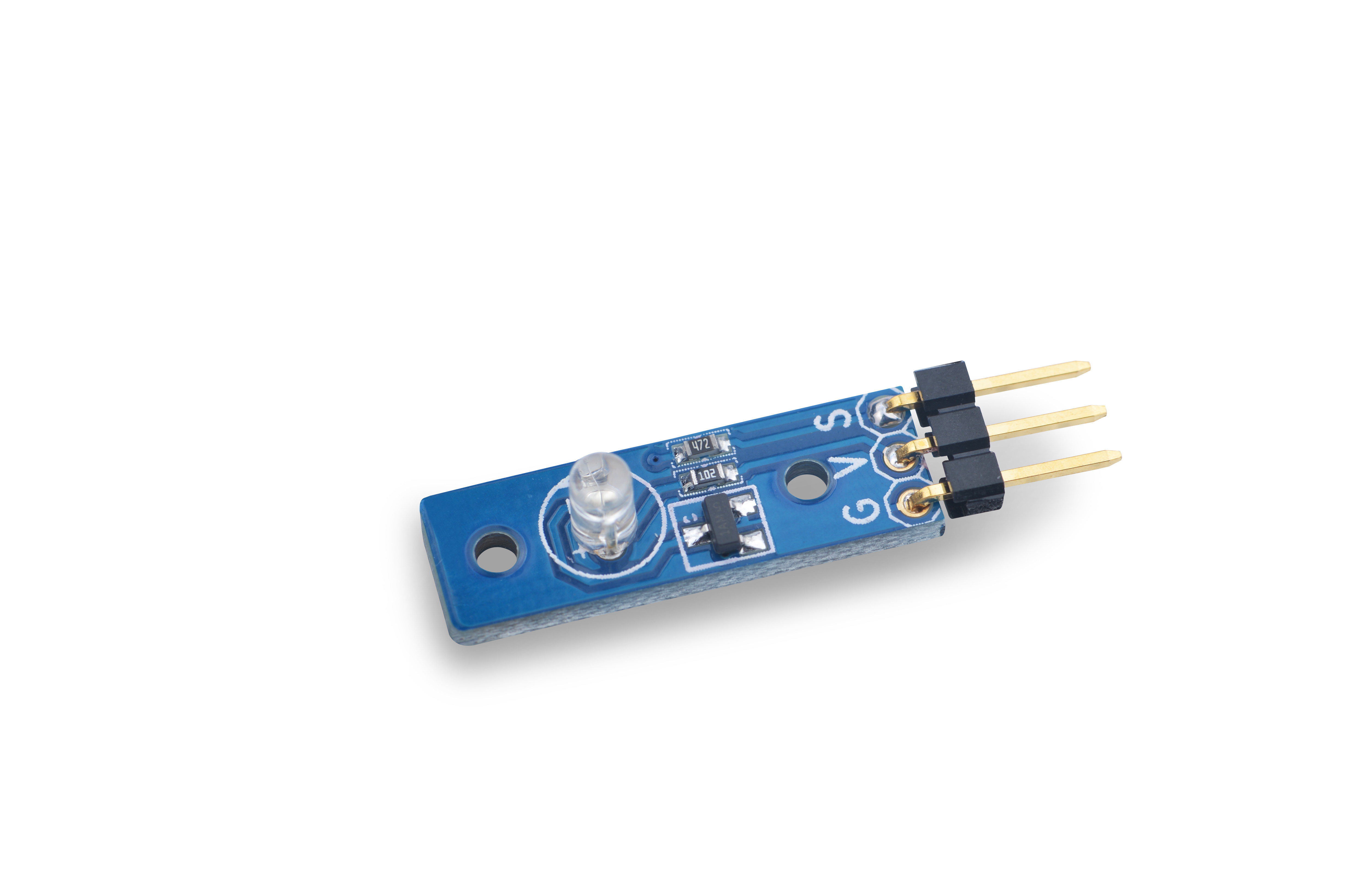
| + | The Matrix-LED is an LED module with three 2.54 mm spacing pins: V(supply voltage),G(ground) and S(signal) which is connected to a triode to turn the LED on or off. You can write high or low, or PWN signals(3.3V or 5V) to S. When you write high to S the LED will turn on and become brightest. When you write low to S the LED will turn off. If you write PWM signals to S the LED's brightness will vary depending on the PWM's signal variances. | ||
| + | |||
| + | ==Features== | ||
| + | * GPIO/PWM interface, 3.3/5V, PWM brightness control | ||
| + | * Small, easy to be used in various situations | ||
| + | * 2.54 mm spacing pin | ||
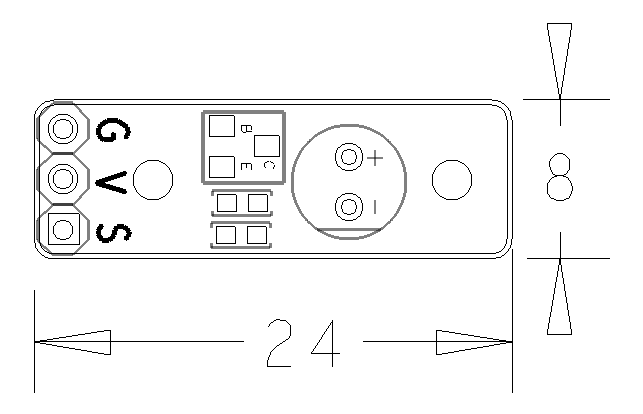
| + | * PCB Dimension(mm): 8 x 24 | ||
| + | [[File:led02pcb.png | frameless|400px|LED-01.PCB]] | ||
| + | |||
| + | * Pin Description: | ||
| + | {| class="wikitable" | ||
| + | |- | ||
| + | |Pin || Description | ||
| + | |- | ||
| + | |S || GPIO | ||
| + | |- | ||
| + | |V || Supply Voltage 5V | ||
| + | |- | ||
| + | |G || Ground | ||
| + | |} | ||
| + | |||
| + | ==Basic Device Operation== | ||
| + | The module has three 2.54 mm spacing pins: V(supply voltage),G(ground) and S(signal) which is connected to a triode to turn the LED on or off. You can write high or low, or PWN signals(3.3V or 5V) to S. When you write high to S the LED will turn on and become brightest. When you write low to S the LED will turn off. If you write PWM signals to S the LED's brightness will vary depending on the PWM's signal variances. | ||
| + | |||
| + | ==Applications== | ||
| + | ===Connect to NanoPi M1=== | ||
| + | Refer to the following connection diagram to connect the module to the NanoPi M1:<br> | ||
| + | [[File:Matrix-LED_nanopi_m1.jpg|frameless|600px|Matrix-LED_nanopi_m1]] | ||
| + | |||
| + | Connection Details: | ||
| + | {| class="wikitable" | ||
| + | |- | ||
| + | |Matrix-LED || NanoPi M1 | ||
| + | |- | ||
| + | |S || Pin7 | ||
| + | |- | ||
| + | |V || Pin4 | ||
| + | |- | ||
| + | |G || Pin6 | ||
| + | |} | ||
| + | |||
| + | ===Connect to NanoPi 2=== | ||
| + | Refer to the following connection diagram to connect the module to the NanoPi 2:<br> | ||
| + | [[File:Matrix-LED_nanopi_2.jpg|frameless|600px|Matrix-LED_nanopi_2]] | ||
| + | |||
| + | Connection Details: | ||
| + | {| class="wikitable" | ||
| + | |- | ||
| + | |Matrix-LED || NanoPi 2 | ||
| + | |- | ||
| + | |S || Pin7 | ||
| + | |- | ||
| + | |V || Pin4 | ||
| + | |- | ||
| + | |G || Pin6 | ||
| + | |} | ||
| + | |||
| + | ===Connect to NanoPi M2 / NanoPi 2 Fire=== | ||
| + | Refer to the following connection diagram to connect the module to the NanoPi M2/ NanoPi 2 Fire:<br> | ||
| + | [[File:Matrix-LED_nanopi_m2.jpg|frameless|600px|Matrix-LED_nanopi_m2]] | ||
| + | |||
| + | Connection Details: | ||
| + | {| class="wikitable" | ||
| + | |- | ||
| + | |Matrix-LED || NanoPi M2 | ||
| + | |- | ||
| + | |S || Pin7 | ||
| + | |- | ||
| + | |V || Pin4 | ||
| + | |- | ||
| + | |G || Pin6 | ||
| + | |} | ||
| + | |||
| + | ===Connect to NanoPC-T2=== | ||
| + | Refer to the following connection diagram to connect the module to the NanoPC-T2:<br> | ||
| + | [[File:Matrix-LED_NanoPC-T2.jpg|frameless|600px|Matrix-LED_NanoPC-T2]] | ||
| + | |||
| + | Connection Details: | ||
| + | {| class="wikitable" | ||
| + | |- | ||
| + | |Matrix-LED || NanoPC-T2 | ||
| + | |- | ||
| + | |S || Pin15 | ||
| + | |- | ||
| + | |V || Pin29 | ||
| + | |- | ||
| + | |G || Pin30 | ||
| + | |} | ||
| + | |||
| + | ==Compile & Run Test Program== | ||
| + | Boot your ARM board with Debian and copy the matrix code: | ||
| + | <syntaxhighlight lang="bash"> | ||
| + | $ apt-get update && apt-get install git | ||
| + | $ git clone https://github.com/friendlyarm/matrix.git | ||
| + | </syntaxhighlight> | ||
| + | If your cloning is done successfully a "matrix" directory will be generated. | ||
| + | |||
| + | Compile and install Matrix: | ||
| + | <syntaxhighlight lang="bash"> | ||
| + | $ cd matrix | ||
| + | $ make && make install | ||
| + | </syntaxhighlight> | ||
| + | |||
| + | Run test program: | ||
| + | <syntaxhighlight lang="bash"> | ||
| + | $ matrix-gpio_out | ||
| + | </syntaxhighlight> | ||
| + | Note: this module is not plug and play therefore before running the module please make sure it is connected to an ARM board.<br> | ||
| + | Here is what you should observe:<br> | ||
| + | <syntaxhighlight lang="bash"> | ||
| + | 1: gpio status change | ||
| + | 2: gpio status change | ||
| + | 3: gpio status change | ||
| + | 4: gpio status change | ||
| + | 5: gpio status change | ||
| + | </syntaxhighlight> | ||
| + | The LED will be blinking continuously. | ||
| + | |||
| + | ==Code Sample== | ||
| + | This Matrix code sample can work with all the ARM boards mentioned in this module's wiki. The name of this code sample is "matrix-gpio_out". Here is its source code: | ||
| + | <syntaxhighlight lang="c"> | ||
| + | int main(int argc, char ** argv) | ||
| + | { | ||
| + | int pin = GPIO_PIN(7); | ||
| + | int i, value, board; | ||
| + | int ret = -1; | ||
| + | |||
| + | if ((board = boardInit()) < 0) { | ||
| + | printf("Fail to init board\n"); | ||
| + | return -1; | ||
| + | } | ||
| + | if (board == BOARD_NANOPI_T2) | ||
| + | pin = GPIO_PIN(15); | ||
| + | |||
| + | if (argc == 2) | ||
| + | pin = GPIO_PIN(atoi(argv[1])); | ||
| + | if ((ret = exportGPIOPin(pin)) == -1) { | ||
| + | printf("exportGPIOPin(%d) failed\n", pin); | ||
| + | } | ||
| + | if ((ret = setGPIODirection(pin, GPIO_OUT)) == -1) { | ||
| + | printf("setGPIODirection(%d) failed\n", pin); | ||
| + | } | ||
| + | for (i = 0; i < STATUS_CHANGE_TIMES; i++) { | ||
| + | if (i % 2) { | ||
| + | value = GPIO_HIGH; | ||
| + | } else { | ||
| + | value = GPIO_LOW; | ||
| + | } | ||
| + | if ((ret = setGPIOValue(pin, value)) > 0) { | ||
| + | printf("%d: GPIO_PIN(%d) value is %d\n", i+1, pin, value); | ||
| + | } else { | ||
| + | printf("setGPIOValue(%d) failed\n", pin); | ||
| + | } | ||
| + | sleep(1); | ||
| + | } | ||
| + | unexportGPIOPin(pin); | ||
| + | return 0; | ||
| + | } | ||
| + | </syntaxhighlight> | ||
| + | For more details about this APIs called in this code sample refer to [[Matrix API reference manual]] <br> | ||
| + | <!--- | ||
| + | ==Download Matrix Source Code== | ||
| + | All the matrix modules' code samples are open source. They are maintained on GitHub - https://github.com/friendlyarm/matrix.git <br> | ||
| + | Each branch in this hub contains the matrix modules' code samples for a board that the matrix modules can work with.<br> | ||
| + | * The nanopi branch contains the matrix modules' code samples for the NanoPi | ||
| + | * The nanopi 2 branch contains the matrix modules' code samples for the NanoPi 2 | ||
| + | * The tiny4412 branch contains the matrix modules' code samples for the Tiny4412 | ||
| + | * The raspberrypi branch contains the matrix modules' code samples for the RaspberryPi | ||
| + | |||
| + | Please follow the steps below to get the source code:<br> | ||
| + | Install the git utility on a PC running Ubuntu14.04 | ||
| + | <syntaxhighlight lang="bash"> | ||
| + | $ sudo apt-get install git | ||
| + | </syntaxhighlight> | ||
| + | |||
| + | Clone the matrix code from GitHub | ||
| + | <syntaxhighlight lang="bash"> | ||
| + | $ git clone https://github.com/friendlyarm/matrix.git | ||
| + | </syntaxhighlight> | ||
| + | If this is successful a "matrix" directory will be generated, which will contain all the matrix modules' code samples. | ||
| + | |||
| + | ==Connect to NanoPi 2== | ||
| + | ===Hardware Connection=== | ||
| + | Please refer to the following connection diagram to connect the Matrix-LED to the NanoPi 2:<br> | ||
| + | [[File:Matrix-LED_nanopi_2.jpg|frameless|600px|Matrix-LED_nanopi_2]] | ||
| + | |||
| + | Connection Details: | ||
| + | {| class="wikitable" | ||
| + | |- | ||
| + | |Matrix-LED || NanoPi | ||
| + | |- | ||
| + | |S || Pin7 | ||
| + | |- | ||
| + | |V || Pin4 | ||
| + | |- | ||
| + | |G || Pin6 | ||
| + | |} | ||
| + | |||
| + | ===Compile Test Program=== | ||
| + | Please login the matrix hub and enter the nanopi2 branch | ||
| + | <syntaxhighlight lang="bash"> | ||
| + | $ cd matrix | ||
| + | $ git checkout nanopi2 | ||
| + | </syntaxhighlight> | ||
| + | |||
| + | Compile the matrix code | ||
| + | <syntaxhighlight lang="bash"> | ||
| + | $ make CROSS_COMPILE=arm-linux- clean | ||
| + | $ make CROSS_COMPILE=arm-linux- | ||
| + | $ make CROSS_COMPILE=arm-linux- install | ||
| + | </syntaxhighlight> | ||
| + | Note: please make sure to install the cross compiler "arm-linux-gcc-4.9.3" on your PC, which is used to compile files for the NanoPi 2.<br> | ||
| + | Generated library files are under the "install/lib" directory. The test program is under the "install/usr/bin" directory.<br> | ||
| + | The modules are under the "modules" directory. The driver's source code is in github: https://github.com/friendlyarm/linux-3.4.y.git <br> | ||
| + | |||
| + | ===Run Test Program=== | ||
| + | Please insert a TF card which is flashed with Debian to a Linux host and mount its boot and rootfs sections.<br> | ||
| + | We assume the rootfs is mounted to /media/rootfs then please run the following commands to copy the module, library and test program to the card.<br> | ||
| + | <syntaxhighlight lang="bash"> | ||
| + | $ cp modules /media/rootfs/ -r | ||
| + | $ cp install/lib/* /media/rootfs/lib/ -d | ||
| + | $ cp install/usr/bin/* /media/rootfs/usr/bin/ | ||
| + | </syntaxhighlight> | ||
| + | |||
| + | Insert this TF card to your NanoPi 2, power on and run the following command to test.<br> | ||
| + | <syntaxhighlight lang="bash"> | ||
| + | $ matrix-led | ||
| + | </syntaxhighlight> | ||
| + | Here is what you expect to observe:<br> | ||
| + | [[File:matrix-led_result.png|frameless|600px|matrix-led_result]] <br> | ||
| + | You can observe that the LED is flashing. | ||
| + | |||
| + | ===Code Sample=== | ||
| + | <syntaxhighlight lang="c"> | ||
| + | int main(int argc, char ** argv) | ||
| + | { | ||
| + | int ledPin = GPIO_PIN(7); | ||
| + | int i = 0; | ||
| + | int ret = -1; | ||
| + | |||
| + | if ((ret = exportGPIOPin(ledPin)) == -1) { | ||
| + | printf("exportGPIOPin(%d) failed\n", ledPin); | ||
| + | } | ||
| + | if ((ret = setGPIODirection(ledPin, GPIO_OUT)) == -1) { | ||
| + | printf("setGPIODirection(%d) failed\n", ledPin); | ||
| + | } | ||
| + | |||
| + | for (i = 0; i < LED_BLINK_TIMES; i++) { | ||
| + | if (i % 2) { | ||
| + | ret = setGPIOValue(ledPin, GPIO_HIGH); | ||
| + | } else { | ||
| + | ret = setGPIOValue(ledPin, GPIO_LOW); | ||
| + | } | ||
| + | if (ret == -1) { | ||
| + | printf("setGPIOValue(%d) failed\n", ledPin); | ||
| + | } | ||
| + | printf("LED blinking times %d\n", i); | ||
| + | sleep(1); | ||
| + | } | ||
| + | unexportGPIOPin(ledPin); | ||
| + | return 0; | ||
| + | } | ||
| + | </syntaxhighlight> | ||
| + | |||
| + | ==Connect to NanoPi== | ||
| + | ===Preparations=== | ||
| + | Please install a Debian on a NanoPi and an appropriate cross compiler on a PC. Please refer to wiki:[[NanoPi/zh|NanoPi]] <br> | ||
| + | Compile a NanoPi kernel. Note: please use the kernel's source code from the nanopi-v4.1.y-matrix branch. <br> | ||
| + | <syntaxhighlight lang="bash"> | ||
| + | $ git clone https://github.com/friendlyarm/linux-4.x.y.git | ||
| + | $ cd linux-4.x.y | ||
| + | $ git checkout nanopi-v4.1.y-matrix | ||
| + | $ make nanopi_defconfig | ||
| + | $ touch .scmversion | ||
| + | $ make | ||
| + | </syntaxhighlight> | ||
| + | |||
| + | ===Hardware Connection=== | ||
| + | Please refer to the following connection diagram to connect the Matrix-LED to the NanoPi <br> | ||
| + | [[File:matrix-led_nanopi.jpg|frameless|600px|matrix-led_nanopi]] | ||
| + | |||
| + | Connection Details: | ||
| + | {| class="wikitable" | ||
| + | |- | ||
| + | |Matrix-LED || NanoPi | ||
| + | |- | ||
| + | |S || Pin7 | ||
| + | |- | ||
| + | |V || Pin4 | ||
| + | |- | ||
| + | |G || Pin6 | ||
| + | |} | ||
| + | |||
| + | ===Compile Test Program=== | ||
| + | Please login the matrix hub and enter the nanopi branch | ||
| + | <syntaxhighlight lang="bash"> | ||
| + | $ cd matrix | ||
| + | $ git checkout nanopi | ||
| + | </syntaxhighlight> | ||
| + | |||
| + | Compile the matrix code | ||
| + | <syntaxhighlight lang="bash"> | ||
| + | $ make CROSS_COMPILE=arm-linux- clean | ||
| + | $ make CROSS_COMPILE=arm-linux- | ||
| + | $ make CROSS_COMPILE=arm-linux- install | ||
| + | </syntaxhighlight> | ||
| + | Note: please make sure to install the cross compiler "arm-linux-gcc-4.4.3" on your PC, which is used to compile files for the NanoPi-Debian.<br> | ||
| + | Generated library files are under the "install/lib" directory. Applications are under the "install/usr/bin" directory. The test program for the "Matrix-LED" module is "matrix-led".<br> | ||
| + | |||
| + | ===Run Test Program=== | ||
| + | Please copy the library files and test program to the NanoPi | ||
| + | <syntaxhighlight lang="bash"> | ||
| + | $ cp install/usr/bin/* nanopi_rootfs/usr/bin/ | ||
| + | $ cp install/lib/* nanopi_rootfs/lib/ -d | ||
| + | </syntaxhighlight> | ||
| + | |||
| + | Power on the NanoPi and run the following command in Debian's terminal <br> | ||
| + | <syntaxhighlight lang="bash"> | ||
| + | $ matrix-led | ||
| + | </syntaxhighlight> | ||
| + | |||
| + | ===Code Sample=== | ||
| + | <syntaxhighlight lang="c"> | ||
| + | int main(int argc, char ** argv) | ||
| + | { | ||
| + | int ledPin = GPIO_PIN1; | ||
| + | int i = 0; | ||
| + | int ret = -1; | ||
| + | |||
| + | if ((ret = exportGPIOPin(ledPin)) == -1) { | ||
| + | printf("exportGPIOPin(%d) failed\n", ledPin); | ||
| + | } | ||
| + | if ((ret = setGPIODirection(ledPin, GPIO_OUT)) == -1) { | ||
| + | printf("setGPIODirection(%d) failed\n", ledPin); | ||
| + | } | ||
| + | |||
| + | for (i = 0; i < LED_BLINK_TIMES; i++) { | ||
| + | if (i % 2) { | ||
| + | ret = setGPIOValue(ledPin, GPIO_HIGH); | ||
| + | } else { | ||
| + | ret = setGPIOValue(ledPin, GPIO_LOW); | ||
| + | } | ||
| + | if (ret == -1) { | ||
| + | printf("setGPIOValue(%d) failed\n", ledPin); | ||
| + | } | ||
| + | printf("LED blinking times %d\n", i); | ||
| + | sleep(1); | ||
| + | } | ||
| + | unexportGPIOPin(ledPin); | ||
| + | return 0; | ||
| + | } | ||
| + | </syntaxhighlight> | ||
| + | |||
| + | ==Connect to Tiny4412== | ||
| + | ===Preparations=== | ||
| + | Please refer to the Tiny4412's user's manual to install a UbuntuCore on the Tiny4412 and install an appropriate cross compiler on a PC.<br> | ||
| + | Note: only the Tiny4412SDK-1506 carrier board can work with this module. | ||
| + | |||
| + | ===Hardware Connection=== | ||
| + | Please refer to the following diagram to connect the Matrix-LED to the Tiny4412 <br> | ||
| + | [[File:matrix-led_tiny4412.jpg|frameless|600px|matrix-led_tiny4412]] | ||
| + | |||
| + | Connection Details: | ||
| + | {| class="wikitable" | ||
| + | |- | ||
| + | |Matrix-LED || Tiny4412 | ||
| + | |- | ||
| + | |S || GPIO1 S | ||
| + | |- | ||
| + | |V || GPIO1 5V | ||
| + | |- | ||
| + | |G || GPIO1 GND | ||
| + | |} | ||
| + | |||
| + | ===Compile Test Program=== | ||
| + | Please login the Matrix hub and enter the matrix-tiny4412 branch | ||
| + | <syntaxhighlight lang="bash"> | ||
| + | $ cd matrix | ||
| + | $ git checkout tiny4412 | ||
| + | </syntaxhighlight> | ||
| + | |||
| + | Compile the matrix code | ||
| + | <syntaxhighlight lang="bash"> | ||
| + | $ make CROSS_COMPILE=arm-linux-gnueabihf- clean | ||
| + | $ make CROSS_COMPILE=arm-linux-gnueabihf- | ||
| + | $ make CROSS_COMPILE=arm-linux-gnueabihf- install | ||
| + | </syntaxhighlight> | ||
| + | Note: please make sure to install the cross compiler "arm-linux-gnueabihf-gcc-4.7.3" on your PC, which is used to compile files for the Tiny4412-UbuntuCore. <br> | ||
| + | Generated library files are under the "install/lib" directory. Applications are under the "install/usr/bin" directory. The test program for the "Matrix-LED" module is "matrix-led". | ||
| + | |||
| + | ===Run Test Program=== | ||
| + | Please copy the library files and test program to the Tiny4412 | ||
| + | <syntaxhighlight lang="bash"> | ||
| + | $ cp install/usr/bin/* tiny4412_rootfs/usr/bin/ | ||
| + | $ cp install/lib/* tiny4412_rootfs/lib/ -d | ||
| + | </syntaxhighlight> | ||
| + | |||
| + | Power on the Tiny4412 and run the following command in UbuntuCore's terminal <br> | ||
| + | <syntaxhighlight lang="bash"> | ||
| + | $ matrix-led | ||
| + | </syntaxhighlight> | ||
| + | |||
| + | ===Code Sample=== | ||
| + | <syntaxhighlight lang="c"> | ||
| + | int main(int argc, char ** argv) | ||
| + | { | ||
| + | int ledPin = GPIO_PIN1; | ||
| + | int i = 0; | ||
| + | int ret = -1; | ||
| + | |||
| + | if ((ret = exportGPIOPin(ledPin)) == -1) { | ||
| + | printf("exportGPIOPin(%d) failed\n", ledPin); | ||
| + | } | ||
| + | if ((ret = setGPIODirection(ledPin, GPIO_OUT)) == -1) { | ||
| + | printf("setGPIODirection(%d) failed\n", ledPin); | ||
| + | } | ||
| + | |||
| + | for (i = 0; i < LED_BLINK_TIMES; i++) { | ||
| + | if (i % 2) { | ||
| + | ret = setGPIOValue(ledPin, GPIO_HIGH); | ||
| + | } else { | ||
| + | ret = setGPIOValue(ledPin, GPIO_LOW); | ||
| + | } | ||
| + | if (ret == -1) { | ||
| + | printf("setGPIOValue(%d) failed\n", ledPin); | ||
| + | } | ||
| + | printf("LED blinking times %d\n", i); | ||
| + | sleep(1); | ||
| + | } | ||
| + | unexportGPIOPin(ledPin); | ||
| + | return 0; | ||
| + | } | ||
| + | </syntaxhighlight> | ||
| + | |||
| + | ==Connect to RaspberryPi== | ||
| + | |||
| + | ==Connect to Arduino== | ||
| + | ---> | ||
| + | |||
| + | ==Resources== | ||
| + | |||
| + | ==Update Log== | ||
| + | ===Feb-18-2016=== | ||
| + | * Added the description for "NanoPi 2 branch" in Section 4 | ||
| + | * Added Section 5: Connect to NanoPi 2 | ||
| + | ===June-21-2016=== | ||
| + | * Re-organized and simplified wiki | ||
<!-- | <!-- | ||
Latest revision as of 14:36, 21 June 2016
Contents
1 Introduction
The Matrix-LED is an LED module with three 2.54 mm spacing pins: V(supply voltage),G(ground) and S(signal) which is connected to a triode to turn the LED on or off. You can write high or low, or PWN signals(3.3V or 5V) to S. When you write high to S the LED will turn on and become brightest. When you write low to S the LED will turn off. If you write PWM signals to S the LED's brightness will vary depending on the PWM's signal variances.
2 Features
- GPIO/PWM interface, 3.3/5V, PWM brightness control
- Small, easy to be used in various situations
- 2.54 mm spacing pin
- PCB Dimension(mm): 8 x 24
- Pin Description:
| Pin | Description |
| S | GPIO |
| V | Supply Voltage 5V |
| G | Ground |
3 Basic Device Operation
The module has three 2.54 mm spacing pins: V(supply voltage),G(ground) and S(signal) which is connected to a triode to turn the LED on or off. You can write high or low, or PWN signals(3.3V or 5V) to S. When you write high to S the LED will turn on and become brightest. When you write low to S the LED will turn off. If you write PWM signals to S the LED's brightness will vary depending on the PWM's signal variances.
4 Applications
4.1 Connect to NanoPi M1
Refer to the following connection diagram to connect the module to the NanoPi M1:
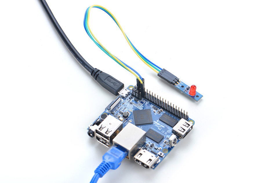
Connection Details:
| Matrix-LED | NanoPi M1 |
| S | Pin7 |
| V | Pin4 |
| G | Pin6 |
4.2 Connect to NanoPi 2
Refer to the following connection diagram to connect the module to the NanoPi 2:
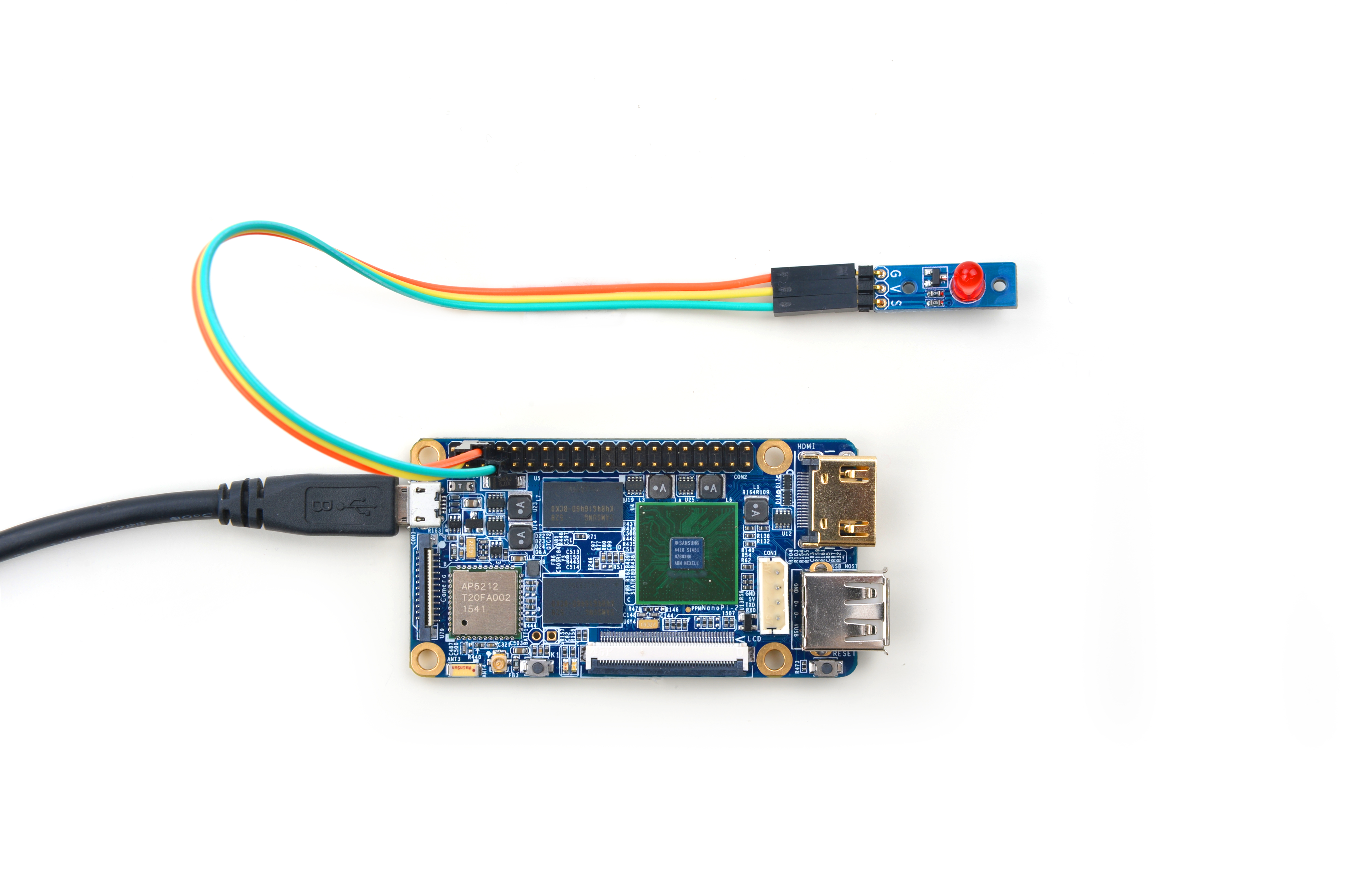
Connection Details:
| Matrix-LED | NanoPi 2 |
| S | Pin7 |
| V | Pin4 |
| G | Pin6 |
4.3 Connect to NanoPi M2 / NanoPi 2 Fire
Refer to the following connection diagram to connect the module to the NanoPi M2/ NanoPi 2 Fire:
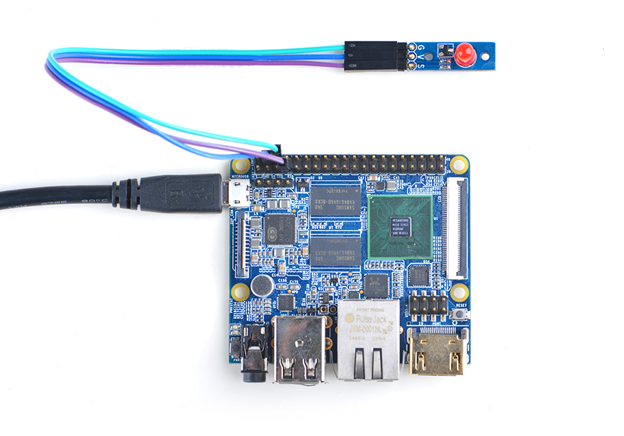
Connection Details:
| Matrix-LED | NanoPi M2 |
| S | Pin7 |
| V | Pin4 |
| G | Pin6 |
4.4 Connect to NanoPC-T2
Refer to the following connection diagram to connect the module to the NanoPC-T2:
Matrix-LED_NanoPC-T2
Connection Details:
| Matrix-LED | NanoPC-T2 |
| S | Pin15 |
| V | Pin29 |
| G | Pin30 |
5 Compile & Run Test Program
Boot your ARM board with Debian and copy the matrix code:
$ apt-get update && apt-get install git
$ git clone https://github.com/friendlyarm/matrix.git
If your cloning is done successfully a "matrix" directory will be generated.
Compile and install Matrix:
$ cd matrix
$ make && make install
Run test program:
$ matrix-gpio_outNote: this module is not plug and play therefore before running the module please make sure it is connected to an ARM board.
Here is what you should observe:
1: gpio status change
2: gpio status change
3: gpio status change
4: gpio status change
5: gpio status change
The LED will be blinking continuously.
6 Code Sample
This Matrix code sample can work with all the ARM boards mentioned in this module's wiki. The name of this code sample is "matrix-gpio_out". Here is its source code:
int main(int argc, char ** argv)
{
    int pin = GPIO_PIN(7);
    int i, value, board;
    int ret = -1;

    if ((board = boardInit()) < 0) {
        printf("Fail to init board\n");
        return -1;
    }
    if (board == BOARD_NANOPI_T2)
        pin = GPIO_PIN(15);

    if (argc == 2)
        pin = GPIO_PIN(atoi(argv[1]));
    if ((ret = exportGPIOPin(pin)) == -1) {
        printf("exportGPIOPin(%d) failed\n", pin);
    }
    if ((ret = setGPIODirection(pin, GPIO_OUT)) == -1) {
        printf("setGPIODirection(%d) failed\n", pin);
    }
    for (i = 0; i < STATUS_CHANGE_TIMES; i++) {
        if (i % 2) {
            value = GPIO_HIGH;
        } else {
            value = GPIO_LOW;
        }
        if ((ret = setGPIOValue(pin, value)) > 0) {
            printf("%d: GPIO_PIN(%d) value is %d\n", i+1, pin, value);
        } else {
            printf("setGPIOValue(%d) failed\n", pin);
        }
        sleep(1);
    }
    unexportGPIOPin(pin);
    return 0;
}
For more details about this APIs called in this code sample refer to Matrix API reference manual
7 Resources
8 Update Log
8.1 Feb-18-2016
- Added the description for "NanoPi 2 branch" in Section 4
- Added Section 5: Connect to NanoPi 2
8.2 June-21-2016
- Re-organized and simplified wiki
