Difference between revisions of "Matrix - Compact Kit"
(→Connect to NanoPi 2) |
(→Applications) |
||
| (30 intermediate revisions by 2 users not shown) | |||
| Line 3: | Line 3: | ||
==Introduction== | ==Introduction== | ||
[[File:Matrix-Compact_Kit.png|thumb|]] | [[File:Matrix-Compact_Kit.png|thumb|]] | ||
| − | *The Matrix-Compact Kit is a compact board with various hardware resources, interfaces and ports | + | *The Matrix-Compact Kit is a compact board with various hardware resources, interfaces and ports. It includes user keys, LED, buzzer, ADC, compass, temperature sensor, IR receiver, TFT port and etc. This board can be connected to the NanoPi, NanoPi 2 and Raspberry Pi via its 40 pin header. In addition you can connect other external modules to its GPIOs. |
| + | ==Features== | ||
| + | * PCB Dimension(mm): | ||
| + | [[File:Matrix-Compact_Kit_PCB.png|frameless|400px|]] | ||
| + | [[File:Matrix-Compact_Kit.png |thumb|300px|Matrix-Compact_Kit Layout]] | ||
| + | * '''40pin female connector's GPIO Pin Spec''' | ||
| + | ::{| class="wikitable" | ||
| + | |- | ||
| + | |Pin# || Name ||Pin# || Name | ||
| + | |- | ||
| + | |1 || VDD_SYS_3.3V ||2 || VDD_5V | ||
| + | |- | ||
| + | |3 || I2C0_SDA ||4 || VDD_5V | ||
| + | |- | ||
| + | |5 || I2C0_SCL ||6 || DGND | ||
| + | |- | ||
| + | |7 || GPIOB28 ||8 || UART3_TXD | ||
| + | |- | ||
| + | |9 || DGND ||10 || UART3_RXD | ||
| + | |- | ||
| + | |11 || GPIOB29 ||12 || GPIOB26 | ||
| + | |- | ||
| + | |13 || GPIOB30 ||14 || DGND | ||
| + | |- | ||
| + | |15 || GPIOB31 ||16 || PWM2 | ||
| + | |- | ||
| + | |17 || VDD_SYS_3.3V ||18 || GPIOB27 | ||
| + | |- | ||
| + | |19 || SPI0_MOSI ||20 || DGND | ||
| + | |- | ||
| + | |21 || SPI0_MISO ||22 || PWM0 | ||
| + | |- | ||
| + | |23 || SPI0_CLK ||24 || SPI0_CS | ||
| + | |- | ||
| + | |25 || DGND ||26 || PWM1 | ||
| + | |- | ||
| + | |27 || I2C1_SDA ||28 || I2C1_SCL | ||
| + | |- | ||
| + | |29 || GPIOC8 ||30 || DGND | ||
| + | |- | ||
| + | |31 || SPI2_CLK ||32 || GPIOC28 | ||
| + | |- | ||
| + | |33 || SPI2_CS ||34 || DGND | ||
| + | |- | ||
| + | |35 || SPI2_MOSI ||36 || GPIOC7 | ||
| + | |- | ||
| + | |37 || SPI2_MISO ||38 || ALIVEGPIO2 | ||
| + | |- | ||
| + | |39 || DGND ||40 || ALIVEGPIO3 | ||
| + | |} | ||
| + | |||
| + | [[File:Matrix-Compact_Kit3*10.png |thumb|300px|Matrix-Compact_Kit Layout]] | ||
| + | * '''30pin Pin Spec''' | ||
| + | ::{| class="wikitable" | ||
| + | |- | ||
| + | |Pin# || Name ||Pin# || Name ||Pin# || Name | ||
| + | |- | ||
| + | |1 || GND ||2 || VDD_5V ||3 ||A1_PCF | ||
| + | |- | ||
| + | |4 || GND ||5 || VDD_5V ||6 ||A2_PCF | ||
| + | |- | ||
| + | |7 || GND ||8 || VDD_5V ||9 ||A3_PCF | ||
| + | |- | ||
| + | |10 || GND ||11 || VDD_5V ||12 ||D1_Pi11 | ||
| + | |- | ||
| + | |13 || GND ||14 || VDD_5V ||15 ||D2_Pi26 | ||
| + | |- | ||
| + | |16 || GND ||17 || VDD_5V ||18 ||D3_Pi16 | ||
| + | |- | ||
| + | |19 || GND ||20 || VDD_5V ||21 ||D4_Pi19 | ||
| + | |- | ||
| + | |22 || GND ||23 || VDD_5V ||24 ||D5_Pi21 | ||
| + | |- | ||
| + | |25 || GND ||26 || VDD_5V ||27 ||D6_Pi23 | ||
| + | |- | ||
| + | |28 || GND ||29 || VDD_5V ||30 ||D7_Pi24 | ||
| + | |- | ||
| + | |} | ||
| + | |||
| + | [[File:18B20 and IRR.png |thumb|300px|18B20 & IR Receiver Layout]] | ||
| + | * '''18B20 & IR Receiver Pin Spec''' | ||
| + | ::{| class="wikitable" | ||
| + | |- | ||
| + | |Module ||Pin# || Name ||Pin# || Name ||Pin# || Name | ||
| + | |- | ||
| + | |18B20 ||1 || VDD_5V ||2 || DATA ||3 || GND | ||
| + | |- | ||
| + | |IR Receiver ||1 || DATA ||2 || GND ||3 || VDD_5V | ||
| + | |- | ||
| + | |} | ||
| + | |||
| + | ==Applications== | ||
| + | ===Connect to NanoPi 2=== | ||
| + | Refer to the following connection diagram to connect the module to the NanoPi 2:<br> | ||
| + | [[File:Matrix-Compact_Kit_nanopi2.jpg|frameless|600px|Matrix-Compact_Kit_nanopi2]] | ||
| + | |||
| + | ==Compile & Run Test Program== | ||
| + | Boot your ARM board with Debian and copy the matrix code: | ||
| + | <syntaxhighlight lang="bash"> | ||
| + | $ apt-get update && apt-get install git | ||
| + | $ git clone https://github.com/friendlyarm/matrix.git | ||
| + | </syntaxhighlight> | ||
| + | If your cloning is done successfully a "matrix" directory will be generated. | ||
| + | |||
| + | Compile and install Matrix: | ||
| + | <syntaxhighlight lang="bash"> | ||
| + | $ cd matrix | ||
| + | $ make && make install | ||
| + | </syntaxhighlight> | ||
| + | |||
| + | Run test program: | ||
| + | <syntaxhighlight lang="bash"> | ||
| + | $ matrix-compact_kit | ||
| + | </syntaxhighlight> | ||
| + | Note: this module is not plug and play therefore before running the module please make sure it is connected to an ARM board.<br> | ||
| + | Here is what you should observe:<br> | ||
| + | <syntaxhighlight lang="bash"> | ||
| + | LED blinking 1 | ||
| + | LED blinking 2 | ||
| + | Button: 1 1 1 | ||
| + | ADC channel0: 550 | ||
| + | Compass angle: 328.5 | ||
| + | Pwm start | ||
| + | Pwm stop | ||
| + | </syntaxhighlight> | ||
| + | |||
| + | Run Qt program to test the TFT LCD: | ||
| + | <syntaxhighlight lang="bash"> | ||
| + | cd matrix/demo/nanopi-status | ||
| + | ./build.sh | ||
| + | ./run.sh /dev/fb-st7735s | ||
| + | </syntaxhighlight> | ||
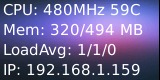
| + | The program will present the system's basic information:<br> | ||
| + | [[File:st7735s-status.pnc|frameless|600px|st7735s-status]] | ||
| + | |||
| + | ==Code Sample== | ||
| + | This Matrix code sample can work with all the ARM boards mentioned in this module's wiki. The name of this code sample is "matrix-compact_kit". Here is its source code: | ||
| + | <syntaxhighlight lang="c"> | ||
| + | int main(int argc, char ** argv) | ||
| + | { | ||
| + | int board; | ||
| + | |||
| + | if ((board = boardInit()) < 0) { | ||
| + | printf("Fail to init board\n"); | ||
| + | return -1; | ||
| + | } | ||
| + | testLED(board); | ||
| + | readButton(); | ||
| + | readADC(); | ||
| + | readCompass(); | ||
| + | testPWM(board); | ||
| + | // readTemp(); | ||
| + | // testIR(); | ||
| + | |||
| + | return 0; | ||
| + | } | ||
| + | </syntaxhighlight> | ||
| + | For more details about this APIs called in this code sample refer to [[Matrix API reference manual]] <br> | ||
| + | |||
| + | ==Code Samples in Python== | ||
| + | The Python version is 2.7.9 in the following samples<br> | ||
| + | Install the Python libraries and modules: | ||
| + | <syntaxhighlight lang="bash"> | ||
| + | $ apt-get install Python-dev libi2c-dev | ||
| + | </syntaxhighlight> | ||
| + | |||
| + | The python code is in our github: | ||
| + | <syntaxhighlight lang="bash"> | ||
| + | $ git clone https://github.com/friendlyarm/matrix-python.git | ||
| + | </syntaxhighlight> | ||
| + | After it is done a matrix-python directory will be generated. | ||
| + | |||
| + | Access LED: | ||
| + | <syntaxhighlight lang="bash"> | ||
| + | $ cd matrix-python/Matrix.GPIO | ||
| + | $ python setup.py install | ||
| + | $ python test/matrix_output.py 33 | ||
| + | </syntaxhighlight> | ||
| + | The red LED will be flashing. | ||
| + | |||
| + | Read KEY1: | ||
| + | <syntaxhighlight lang="bash"> | ||
| + | $ cd matrix-python/Matrix.GPIO | ||
| + | $ python setup.py install | ||
| + | $ python test/matrix_input.py 36 | ||
| + | </syntaxhighlight> | ||
| + | When you press KEY1 "value" will be set to 0. When you release KEY1 "value" will be set to 1. | ||
| + | |||
| + | Test AD: | ||
| + | <syntaxhighlight lang="bash"> | ||
| + | $ cd matrix-python/modules | ||
| + | $ modprobe pcf8591 | ||
| + | $ cd ../Matrix.pcf8591 | ||
| + | $ python setup.py install | ||
| + | $ python test/matrix_adc.py | ||
| + | </syntaxhighlight> | ||
| + | When you change the resistor AD value will be changed accordingly. | ||
| + | |||
| + | Test Compass: | ||
| + | <syntaxhighlight lang="bash"> | ||
| + | $ cd matrix-python/Matrix.I2C | ||
| + | $ python setup.py install | ||
| + | $ python test/matrix_compass.py | ||
| + | </syntaxhighlight> | ||
| + | When you rotate the compass you will get changing direction values. | ||
| + | |||
| + | <!--- | ||
==Features== | ==Features== | ||
Matrix - Compact Kit has the following onboard resources:<br> | Matrix - Compact Kit has the following onboard resources:<br> | ||
| Line 17: | Line 223: | ||
* ADC | * ADC | ||
| − | * | + | * Potentiometer |
* 40 pin female connector | * 40 pin female connector | ||
| Line 27: | Line 233: | ||
* 3 pin double row pin-header - 3.3V and GND | * 3 pin double row pin-header - 3.3V and GND | ||
| − | * | + | * DS18B20 temperature sensor |
* IR receiver | * IR receiver | ||
| Line 36: | Line 242: | ||
==Dimensional Diagram and Pin Description== | ==Dimensional Diagram and Pin Description== | ||
| − | * PCB Dimension(mm): | + | * PCB Dimension (mm): |
[[File:Matrix-Compact_Kit_PCB.png|frameless|400px|]] | [[File:Matrix-Compact_Kit_PCB.png|frameless|400px|]] | ||
[[File:Matrix-Compact_Kit01.png |thumb|300px|Matrix-Compact_Kit Interface]] | [[File:Matrix-Compact_Kit01.png |thumb|300px|Matrix-Compact_Kit Interface]] | ||
| Line 113: | Line 319: | ||
|} | |} | ||
| − | [[File:18B20 and IRR.png |thumb|300px| | + | [[File:18B20 and IRR.png |thumb|300px|DS18B20 and IR receiver's interface]] |
| − | * ''' | + | * '''DS18B20 and IR receiver's pin description''' |
::{| class="wikitable" | ::{| class="wikitable" | ||
|- | |- | ||
| Line 133: | Line 339: | ||
* The matrix-raspberrypi branch contains the matrix modules' code samples for the RaspberryPi; | * The matrix-raspberrypi branch contains the matrix modules' code samples for the RaspberryPi; | ||
| − | + | Follow the steps below to get the source code:<br> | |
Install the git utility on a PC running Ubuntu14.04 | Install the git utility on a PC running Ubuntu14.04 | ||
<syntaxhighlight lang="bash"> | <syntaxhighlight lang="bash"> | ||
| Line 147: | Line 353: | ||
==Connect to NanoPi 2== | ==Connect to NanoPi 2== | ||
===Hardware Connection=== | ===Hardware Connection=== | ||
| − | + | Refer to the following connection diagram to connect the Matrix-Compact_Kit to the NanoPi 2:<br> | |
[[File:Matrix-Compact_Kit_nanopi2.jpg|frameless|600px|Matrix-Compact_Kit_nanopi2]] | [[File:Matrix-Compact_Kit_nanopi2.jpg|frameless|600px|Matrix-Compact_Kit_nanopi2]] | ||
===Compile Test Program=== | ===Compile Test Program=== | ||
| − | + | Login to the matrix hub and enter the nanopi2 branch | |
<syntaxhighlight lang="bash"> | <syntaxhighlight lang="bash"> | ||
$ cd matrix | $ cd matrix | ||
| Line 163: | Line 369: | ||
$ make CROSS_COMPILE=arm-linux- install | $ make CROSS_COMPILE=arm-linux- install | ||
</syntaxhighlight> | </syntaxhighlight> | ||
| − | Note: | + | Note: make sure to install the cross compiler "arm-linux-gcc-4.9.3" on your PC, which is used to compile files for the NanoPi 2.<br> |
| − | Generated library files are under the "install/lib" directory. The test program is under the "install/usr/bin" directory. The modules are under the "modules" directory<br> | + | Generated library files are under the "install/lib" directory. The test program is under the "install/usr/bin" directory.<br> |
| + | The modules are under the "modules" directory. The driver's source code is in github: https://github.com/friendlyarm/linux-3.4.y.git <br> | ||
===Copy Test Program=== | ===Copy Test Program=== | ||
| − | + | Insert a TF card which is flashed with Debian into a Linux host and mount its boot and rootfs sections.<br> | |
| − | We assume the rootfs is mounted to /media/rootfs then | + | We assume the rootfs is mounted to /media/rootfs then run the following commands to copy the module, library and test program to the card<br> |
<syntaxhighlight lang="bash"> | <syntaxhighlight lang="bash"> | ||
$ cp modules /media/rootfs/ -r | $ cp modules /media/rootfs/ -r | ||
| Line 199: | Line 406: | ||
|LED4 || GPIOC12 || 76 | |LED4 || GPIOC12 || 76 | ||
|} | |} | ||
| − | We | + | We used LED1 as an example. Run the following commands to access LED1: |
<syntaxhighlight lang="bash"> | <syntaxhighlight lang="bash"> | ||
$ cd /sys/class/gpio/ | $ cd /sys/class/gpio/ | ||
| Line 219: | Line 426: | ||
|KEY3 || ALIVEGPIO3 || 163 | |KEY3 || ALIVEGPIO3 || 163 | ||
|} | |} | ||
| − | We | + | We used KEY1 as an example. Running the following commands reads its value: |
<syntaxhighlight lang="bash"> | <syntaxhighlight lang="bash"> | ||
$ cd /sys/class/gpio/ | $ cd /sys/class/gpio/ | ||
| Line 229: | Line 436: | ||
===Test AD=== | ===Test AD=== | ||
| − | + | Run the following command to get Channel 0's value: | |
<syntaxhighlight lang="bash"> | <syntaxhighlight lang="bash"> | ||
$ matrix-adc | $ matrix-adc | ||
</syntaxhighlight> | </syntaxhighlight> | ||
| − | When you turn the resistor the AD value will | + | When you turn the resistor the AD value will change. Here is what you should expect:<br> |
[[File:matrix-cpt_kit_result2.png|frameless|600px|matrix-cpt_kit_result_ad]] | [[File:matrix-cpt_kit_result2.png|frameless|600px|matrix-cpt_kit_result_ad]] | ||
===Test Compass=== | ===Test Compass=== | ||
| − | + | Run the following command to activate the compass: | |
<syntaxhighlight lang="bash"> | <syntaxhighlight lang="bash"> | ||
$ matrix-compass | $ matrix-compass | ||
</syntaxhighlight> | </syntaxhighlight> | ||
| − | When you change the module's | + | When you change the module's direction you will get a changing value. Here is what you should expect:<br> |
[[File:matrix-cpt_kit_result3.png|frameless|600px|matrix-cpt_kit_result_cps]] | [[File:matrix-cpt_kit_result3.png|frameless|600px|matrix-cpt_kit_result_cps]] | ||
| − | === | + | ===Test Temperature Sensor=== |
| − | + | Refer to the following connection diagram to connect the Matrix-Compact_Kit to the DS18B20 temperature sensor:<br> | |
[[File:Matrix-Compact_Kit_ds18b20.jpg|frameless|600px|Matrix-Compact_Kit_ds18b20]] | [[File:Matrix-Compact_Kit_ds18b20.jpg|frameless|600px|Matrix-Compact_Kit_ds18b20]] | ||
| − | + | Run the following commands: | |
<syntaxhighlight lang="bash"> | <syntaxhighlight lang="bash"> | ||
$ cd /modules | $ cd /modules | ||
$ insmod w1-gpio.ko | $ insmod w1-gpio.ko | ||
| − | $ insmod | + | $ insmod w1-gpio-board gpio=72 |
$ matrix-temp_sensor | $ matrix-temp_sensor | ||
</syntaxhighlight> | </syntaxhighlight> | ||
| − | gpio= | + | gpio=72 means pin GPIOC8 is used. 72 is the index number in Linux.<br> |
| − | + | Here is what you should expect:<br> | |
[[File:matrix-temperature_sensor_result.png|frameless|600px|matrix-temperature_sensor_result]] | [[File:matrix-temperature_sensor_result.png|frameless|600px|matrix-temperature_sensor_result]] | ||
| − | === | + | ===Test IR Receiver=== |
| − | + | Refer to the following connection diagram to connect the Matrix-Compact_Kit to the VS1833B IR receiver:<br> | |
[[File:Matrix-Compact_Kit_vs1833b.jpg|frameless|600px|Matrix-Compact_Kit_vs1833b]] | [[File:Matrix-Compact_Kit_vs1833b.jpg|frameless|600px|Matrix-Compact_Kit_vs1833b]] | ||
| − | + | Run the following commands: | |
<syntaxhighlight lang="bash"> | <syntaxhighlight lang="bash"> | ||
$ cd /modules | $ cd /modules | ||
$ insmod matrix_ir_recv.ko gpio=92 | $ insmod matrix_ir_recv.ko gpio=92 | ||
</syntaxhighlight> | </syntaxhighlight> | ||
| − | gpio= | + | gpio=92 means pin GPIOC28 is used. 92 is the index number in Linux.<br> |
| − | + | After the driver is successfully loaded a device node will be generated under /dev/input/. We assume it is event1 in our example.<br> | |
| − | + | An open source utility "input-utils" can be used to read a device's data. Here is how to do it:<br> | |
<syntaxhighlight lang="bash"> | <syntaxhighlight lang="bash"> | ||
$ apt-get install input-utils | $ apt-get install input-utils | ||
$ input-events 1 | $ input-events 1 | ||
</syntaxhighlight> | </syntaxhighlight> | ||
| − | + | 1 stands for device node event1。<br> | |
| − | + | If you send data to the IR receiver with a remote control you will be able to see this:<br> | |
[[File:matrix-ir_receiver_result.png|frameless|600px|matrix-ir_receiver_result]] | [[File:matrix-ir_receiver_result.png|frameless|600px|matrix-ir_receiver_result]] | ||
| − | === | + | ===Code Samples in Python=== |
| − | + | The Python version is 2.7.9 in the following samples<br> | |
| − | + | Install the Python libraries and modules: | |
| + | <syntaxhighlight lang="bash"> | ||
| + | $ apt-get install Python-dev | ||
| + | $ apt-get install libi2c-dev | ||
| + | </syntaxhighlight> | ||
| + | The python code is in our github: | ||
<syntaxhighlight lang="bash"> | <syntaxhighlight lang="bash"> | ||
$ git clone https://github.com/friendlyarm/matrix-python.git | $ git clone https://github.com/friendlyarm/matrix-python.git | ||
</syntaxhighlight> | </syntaxhighlight> | ||
| − | + | After it is done a matrix-python directory will be generated. | |
| + | |||
| − | + | Access LED: | |
<syntaxhighlight lang="bash"> | <syntaxhighlight lang="bash"> | ||
$ cd matrix-python/Matrix.GPIO | $ cd matrix-python/Matrix.GPIO | ||
| Line 295: | Line 508: | ||
$ python test/matrix_output.py 33 | $ python test/matrix_output.py 33 | ||
</syntaxhighlight> | </syntaxhighlight> | ||
| − | + | The red LED will be flashing. | |
| − | + | Read KEY1: | |
<syntaxhighlight lang="bash"> | <syntaxhighlight lang="bash"> | ||
$ cd matrix-python/Matrix.GPIO | $ cd matrix-python/Matrix.GPIO | ||
| Line 303: | Line 516: | ||
$ python test/matrix_input.py 36 | $ python test/matrix_input.py 36 | ||
</syntaxhighlight> | </syntaxhighlight> | ||
| − | + | When you press KEY1 "value" will be set to 0. When you release KEY1 "value" will be set to 1. | |
| − | + | Test AD: | |
<syntaxhighlight lang="bash"> | <syntaxhighlight lang="bash"> | ||
$ cd matrix-python/modules | $ cd matrix-python/modules | ||
| Line 313: | Line 526: | ||
$ python test/matrix_adc.py | $ python test/matrix_adc.py | ||
</syntaxhighlight> | </syntaxhighlight> | ||
| − | + | When you change the resistor AD value will be changed accordingly. | |
| − | + | Test Compass: | |
<syntaxhighlight lang="bash"> | <syntaxhighlight lang="bash"> | ||
$ cd matrix-python/Matrix.I2C | $ cd matrix-python/Matrix.I2C | ||
| Line 321: | Line 534: | ||
$ python test/matrix_compass.py | $ python test/matrix_compass.py | ||
</syntaxhighlight> | </syntaxhighlight> | ||
| − | + | When you rotate the compass you will get changing direction values | |
==Connect to NanoPi== | ==Connect to NanoPi== | ||
| Line 330: | Line 543: | ||
==Connect to Arduino== | ==Connect to Arduino== | ||
| + | ---> | ||
==Resources== | ==Resources== | ||
| + | *[Schematic]([http://wiki.friendlyarm.com/wiki/images/9/94/Schematic-Martix_Compact_Kit.pdf Matrix - Compact Kit-Schematic.pdf]) | ||
*[Schematic]([http://pan.baidu.com/s/1pJQ29Az?qq-pf-to=pcqq.temporaryc2c Matrix - Compact Kit-Schematic.pdf]) | *[Schematic]([http://pan.baidu.com/s/1pJQ29Az?qq-pf-to=pcqq.temporaryc2c Matrix - Compact Kit-Schematic.pdf]) | ||
| + | *[0.9'LCD datasheet]([http://wiki.friendlyarm.com/wiki/images/3/3b/0.9inch_TFT_ST7735S.pdf Matrix - Compact Kit-0.9'LCD datasheet.pdf]) | ||
| + | |||
| + | ==Update Log== | ||
| + | ===Feb-17-2016=== | ||
| + | * Added 5.9, 5.10 and 5.11 | ||
| + | |||
| + | ===Feb-24-2016=== | ||
| + | * Added the driver's source code location in Section 5.2 | ||
| + | |||
| + | ===Mar-21-2016=== | ||
| + | * Corrected typo in Section 5.9 | ||
| + | * Added lib installation steps in Section 5.11 | ||
| + | |||
| + | ===Mar-29-2016=== | ||
| + | * Corrected expression errors | ||
| + | |||
| + | ===June-19-2016=== | ||
| + | * Re-organized and simplified wiki | ||
Latest revision as of 10:32, 19 June 2016
Contents
1 Introduction

- The Matrix-Compact Kit is a compact board with various hardware resources, interfaces and ports. It includes user keys, LED, buzzer, ADC, compass, temperature sensor, IR receiver, TFT port and etc. This board can be connected to the NanoPi, NanoPi 2 and Raspberry Pi via its 40 pin header. In addition you can connect other external modules to its GPIOs.
2 Features
- PCB Dimension(mm):

- 40pin female connector's GPIO Pin Spec
Pin# Name Pin# Name 1 VDD_SYS_3.3V 2 VDD_5V 3 I2C0_SDA 4 VDD_5V 5 I2C0_SCL 6 DGND 7 GPIOB28 8 UART3_TXD 9 DGND 10 UART3_RXD 11 GPIOB29 12 GPIOB26 13 GPIOB30 14 DGND 15 GPIOB31 16 PWM2 17 VDD_SYS_3.3V 18 GPIOB27 19 SPI0_MOSI 20 DGND 21 SPI0_MISO 22 PWM0 23 SPI0_CLK 24 SPI0_CS 25 DGND 26 PWM1 27 I2C1_SDA 28 I2C1_SCL 29 GPIOC8 30 DGND 31 SPI2_CLK 32 GPIOC28 33 SPI2_CS 34 DGND 35 SPI2_MOSI 36 GPIOC7 37 SPI2_MISO 38 ALIVEGPIO2 39 DGND 40 ALIVEGPIO3

- 30pin Pin Spec
Pin# Name Pin# Name Pin# Name 1 GND 2 VDD_5V 3 A1_PCF 4 GND 5 VDD_5V 6 A2_PCF 7 GND 8 VDD_5V 9 A3_PCF 10 GND 11 VDD_5V 12 D1_Pi11 13 GND 14 VDD_5V 15 D2_Pi26 16 GND 17 VDD_5V 18 D3_Pi16 19 GND 20 VDD_5V 21 D4_Pi19 22 GND 23 VDD_5V 24 D5_Pi21 25 GND 26 VDD_5V 27 D6_Pi23 28 GND 29 VDD_5V 30 D7_Pi24

- 18B20 & IR Receiver Pin Spec
Module Pin# Name Pin# Name Pin# Name 18B20 1 VDD_5V 2 DATA 3 GND IR Receiver 1 DATA 2 GND 3 VDD_5V
3 Applications
3.1 Connect to NanoPi 2
Refer to the following connection diagram to connect the module to the NanoPi 2:

4 Compile & Run Test Program
Boot your ARM board with Debian and copy the matrix code:
$ apt-get update && apt-get install git
$ git clone https://github.com/friendlyarm/matrix.git
If your cloning is done successfully a "matrix" directory will be generated.
Compile and install Matrix:
$ cd matrix
$ make && make install
Run test program:
$ matrix-compact_kitNote: this module is not plug and play therefore before running the module please make sure it is connected to an ARM board.
Here is what you should observe:
LED blinking 1
LED blinking 2
Button:  1 1 1
ADC channel0: 550
Compass angle: 328.5
Pwm start
Pwm stop
Run Qt program to test the TFT LCD:
cd matrix/demo/nanopi-status
./build.sh
./run.sh /dev/fb-st7735s
The program will present the system's basic information:
5 Code Sample
This Matrix code sample can work with all the ARM boards mentioned in this module's wiki. The name of this code sample is "matrix-compact_kit". Here is its source code:
int main(int argc, char ** argv)
{
    int board;

    if ((board = boardInit()) < 0) {
        printf("Fail to init board\n");
        return -1;
    }
    testLED(board);
    readButton();
    readADC();
    readCompass();
    testPWM(board);
    // readTemp();
    // testIR();

    return 0;
}
For more details about this APIs called in this code sample refer to Matrix API reference manual
6 Code Samples in Python
The Python version is 2.7.9 in the following samples
Install the Python libraries and modules:
$ apt-get install Python-dev libi2c-dev
The python code is in our github:
$ git clone https://github.com/friendlyarm/matrix-python.git
After it is done a matrix-python directory will be generated.
Access LED:
$ cd matrix-python/Matrix.GPIO
$ python setup.py install
$ python test/matrix_output.py 33
The red LED will be flashing.
Read KEY1:
$ cd matrix-python/Matrix.GPIO
$ python setup.py install
$ python test/matrix_input.py 36
When you press KEY1 "value" will be set to 0. When you release KEY1 "value" will be set to 1.
Test AD:
$ cd matrix-python/modules
$ modprobe pcf8591
$ cd ../Matrix.pcf8591
$ python setup.py install
$ python test/matrix_adc.py
When you change the resistor AD value will be changed accordingly.
Test Compass:
$ cd matrix-python/Matrix.I2C
$ python setup.py install
$ python test/matrix_compass.py
When you rotate the compass you will get changing direction values.
7 Resources
- [Schematic](Matrix - Compact Kit-Schematic.pdf)
- [Schematic](Matrix - Compact Kit-Schematic.pdf)
- [0.9'LCD datasheet](Matrix - Compact Kit-0.9'LCD datasheet.pdf)
8 Update Log
8.1 Feb-17-2016
- Added 5.9, 5.10 and 5.11
8.2 Feb-24-2016
- Added the driver's source code location in Section 5.2
8.3 Mar-21-2016
- Corrected typo in Section 5.9
- Added lib installation steps in Section 5.11
8.4 Mar-29-2016
- Corrected expression errors
8.5 June-19-2016
- Re-organized and simplified wiki