Matrix - LED
From FriendlyELEC WiKi
Contents
1 Introduction
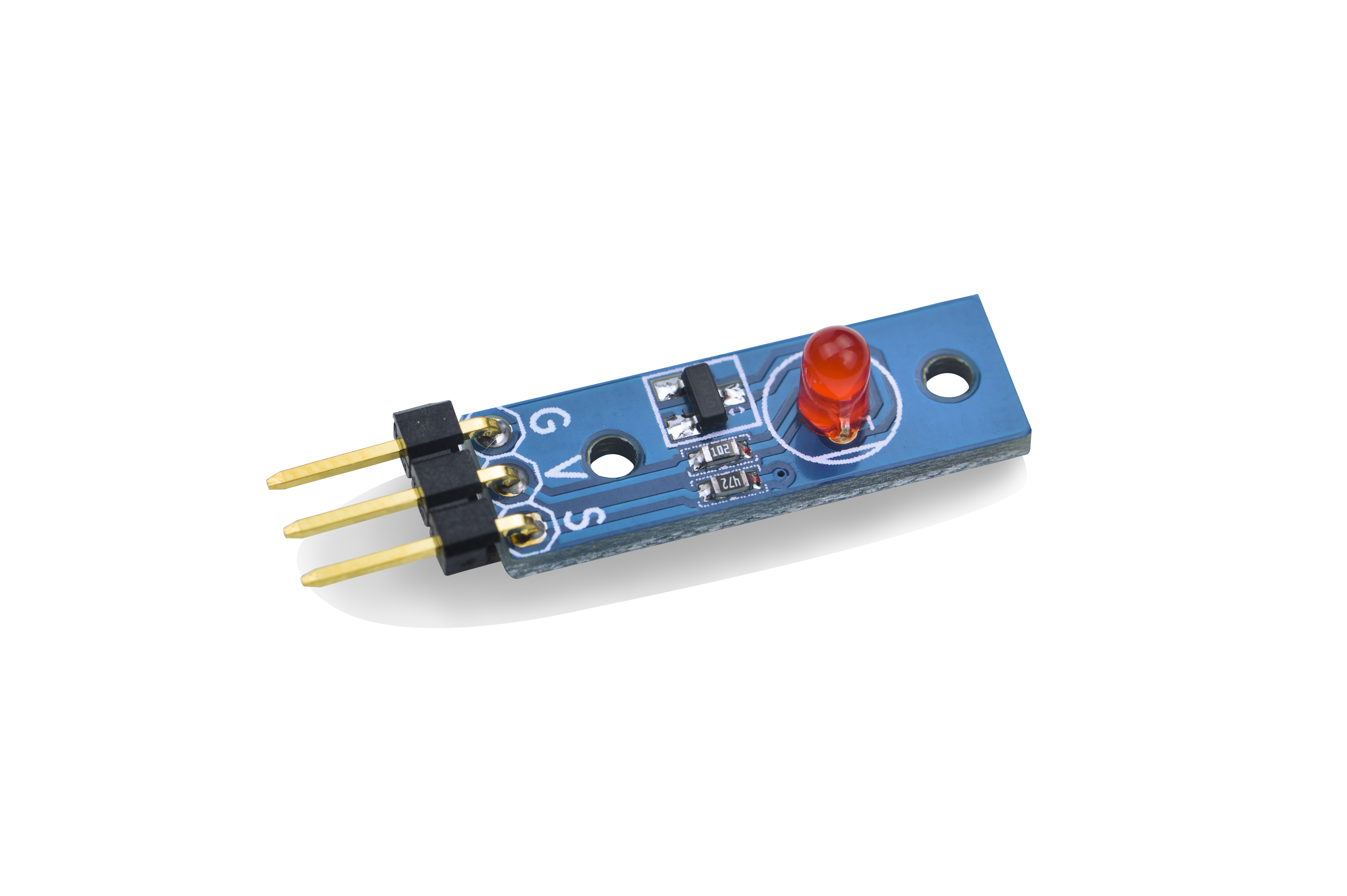
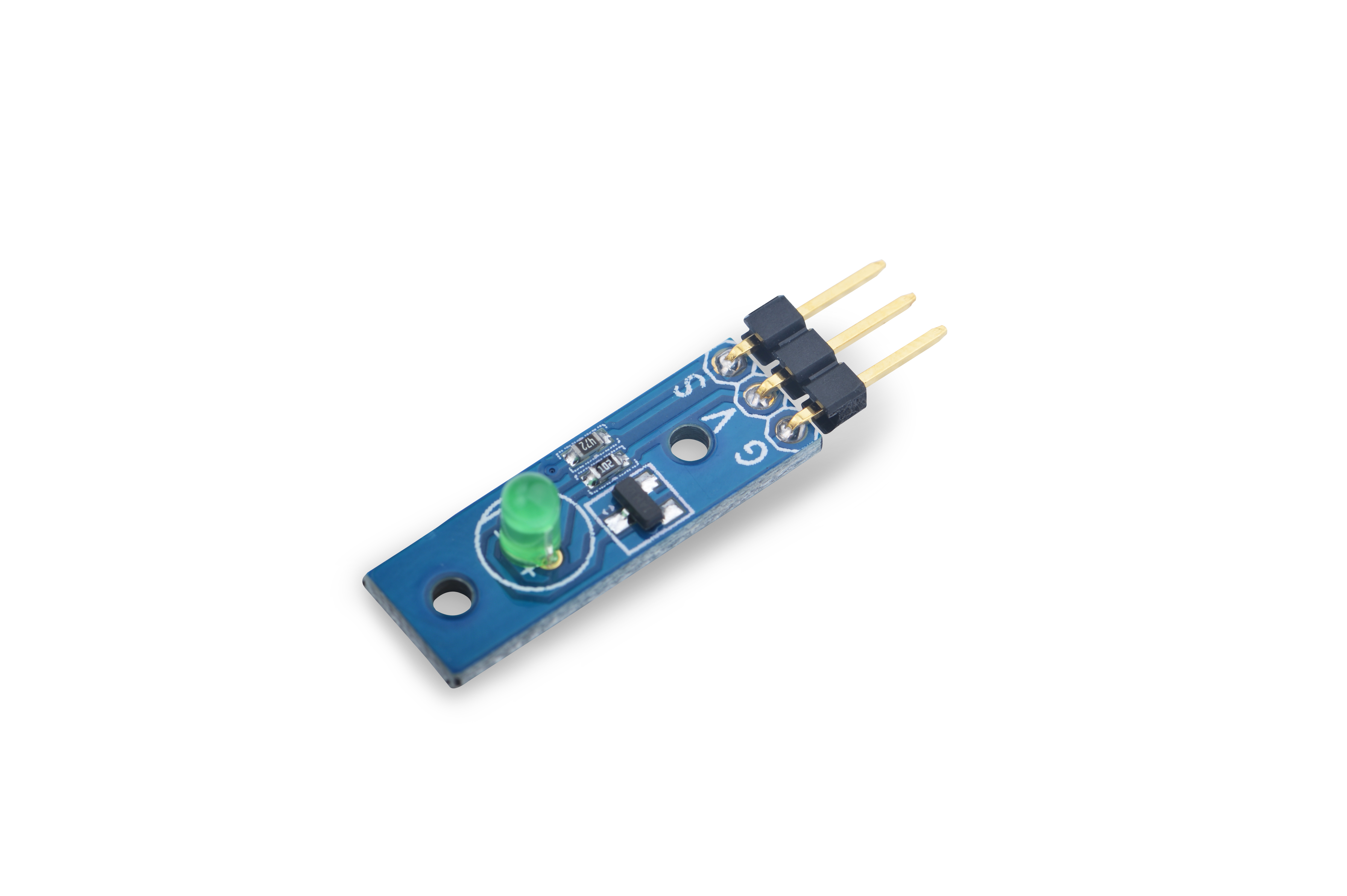
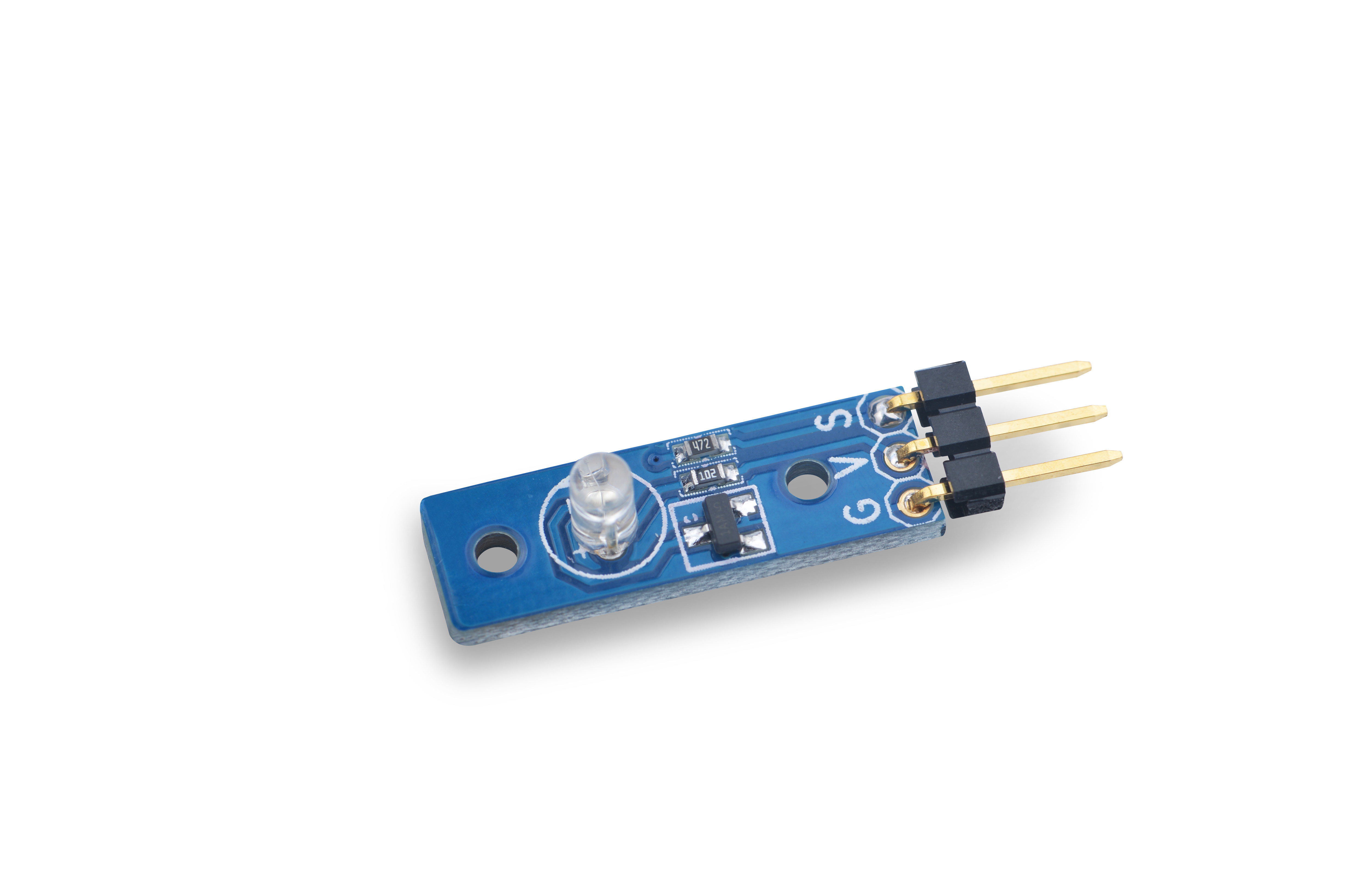
On this module we put a 5mm LED and extend all pins to a 3-Pin 2.54mm spacing pin header. Pin V is power, G is grounded and S is data which is connected to a triode to turn the LED on or off. You can write high or low, or PWN signals(3.3V or 5V) to S. When you write high to S the LED will turn on and become brightest. When you write low to S the LED will turn off. If you write PWM signals to S the LED's brightness will vary depending on the PWM's signal variances. We provide red, green and white LED modules.
2 Features
- GPIO/PWM interface, 3.3/5V, PWM brightness control
- Tiny, easy to be used in various situations
- 2.54mm spacing pin
3 How To
3.1 Connection
- Connect to Tiny4412 SDK (1506)
- Connect the module's pin S to GPIO PIN1, V to 5V and G grounded
3.2 Code Sample in C Under Linux
#include <stdio.h>
#include <unistd.h>
#include "libfahw.h"

#define LED_BLINK_TIMES     10

int main(int argc, char ** argv)
{
    int ledPin = TINY4412_GPIO_PIN1;
    int i = 0;
    int ret = -1;

    if ((ret = exportGPIOPin(ledPin)) == -1) {
        printf("exportGPIOPin(%d) failed\n", ledPin);
    }
    if ((ret = setGPIODirection(ledPin, GPIO_OUT)) == -1) {
        printf("setGPIODirection(%d) failed\n", ledPin);
    }

    for (i = 0; i < LED_BLINK_TIMES; i++) {
        if (i % 2) {
            ret = setGPIOValue(ledPin, GPIO_HIGH);
        } else {
            ret = setGPIOValue(ledPin, GPIO_LOW);
        }
        if (ret == -1) {
            printf("setGPIOValue(%d) failed\n", ledPin);
        }
        printf("LED blinking times %d\n", i);
        sleep(1);
    }
    unexportGPIOPin(ledPin);
    return 0;
}
3.3 Compile and Run
git clone http://github.com/friendlyarm/fa-hardware.git
cd fa-hardware
cd demo
cd matrix-led
make
Copy your compiled bin to your board and you are ready to go.


