NanoPi NEO
Contents
1 Introduction
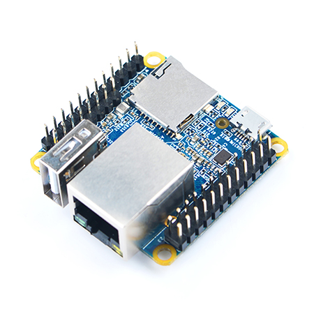
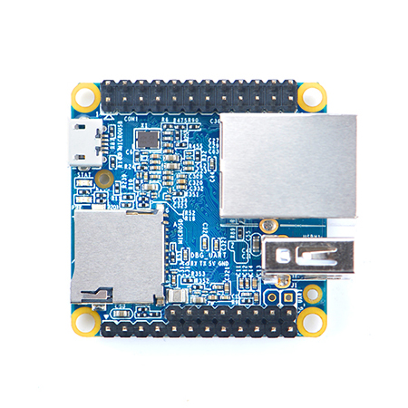
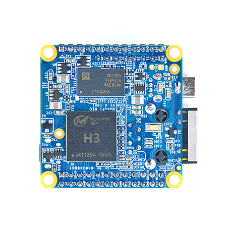
- The NanoPi NEO(abbreviated as NEO) is another fun board developed by FriendlyARM for makers, hobbyists and fans.
2 Features
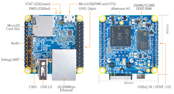
- CPU: Allwinner H3, Quad-core Cortex-A7 Up to 1.2GHz
- DDR3 RAM: 256MB/512MB
- Connectivity: 10/100M Ethernet
- USB Host: Type-A x 1, 2.54 mm pin x 2
- MicroSD Slot x 1
- MicroUSB: for data transmission and power input
- Debug Serial Port: 4Pin, 2.54 mm pitch pin header
- GPIO: 2.54mm pitch 36pin. It includes UART, SPI, I2C, IO etc
- PCB Dimension: 40 x 40 mm
- Power Supply: DC 5V/2A
- OS/Software: u-boot and UbuntuCore
3 Diagram, Layout and Dimension
3.1 Layout
- GPIO Pin Description
Pin# Name Linux gpio Pin# Name Linux gpio 1 SYS_3.3V 2 VDD_5V 3 I2C0_SDA 4 VDD_5V 5 I2C0_SCL 6 GND 7 GPIOG11 203 8 UART1_TX/GPIOG6 198 9 GND 10 UART1_RX/GPIOG7 199 11 UART2_TX/GPIOA0 0 12 PWM1/GPIOA6 6 13 UART2_RTS/GPIOA2 2 14 GND 15 UART2_CTS/GPIOA3 3 16 UART1_RTS/GPIOG8 200 17 SYS_3.3V 18 UART1_CTS/GPIOG9 201 19 SPI0_MOSI/GPIOC0 64 20 GND 21 SIP0_MISO/GPIOC1 65 22 UART2_RX/GPIOA1 1 23 SPI0_CLK/GPIOC29 93 24 SPI0_CS/GPIOC3 67
- USB/Audio/IR Pin Description
Pin# Name Description 1 VDD_5V 5V Power Out 2 USB-DP1 USB1 DP Signal 3 USB-DM1 USB1 DM Signal 4 USB-DP2 USB2 DP Signal 5 USB-DM2 USB2 DM Signal 6 GPIOL11/IR-RX GPIOL11 or IR Receive 7 SPDIF-OUT/GPIOA17 GPIOA17 or SPDIF-OUT 8 MICIN1P Microphone Positive Input 9 MICIN1N Microphone Negative Input 10 LINEOUTR LINE-OUT Right Channel Output 11 LINEOUTL LINE-OUT Left Channel Output 12 GND 0V
- Debug Port(UART0)
Pin# Name 1 GND 2 VDD_5V 3 UART_TXD0 4 UART_RXD0
- Note:
- SYS_3.3V: 3.3V power output
- VVDD_5V: 5V power input/output. When the external device’s power is greater than the MicroUSB's the external device is charging the board otherwise the board powers the external device. The input range is 4.7V ~ 5.6V
- All pins are 3.3V, output current is 5mA
- For more details refer to the document: NanoPi-NEO-1606-Schematic.pdf
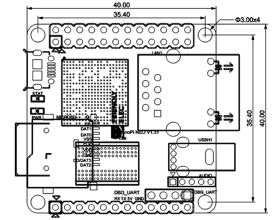
3.2 Dimensional Diagram
- For more details refer to the document: pcb file in dxf format
4 Get Started
4.1 Essentials You Need
Before starting to use your NanoPi NEO get the following items ready
- NanoPi NEO
- microSD Card/TFCard: Class 10 or Above, minimum 8GB SDHC
- microUSB power. A 5V/2A power is a must
- A Host computer running Ubuntu 14.04 64 bit system
4.2 TF Cards We Tested
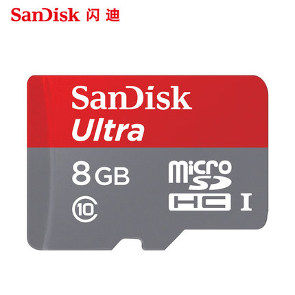
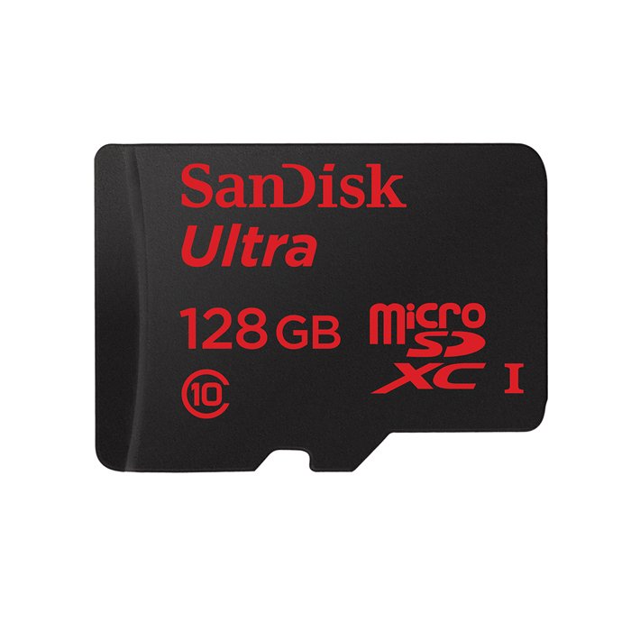
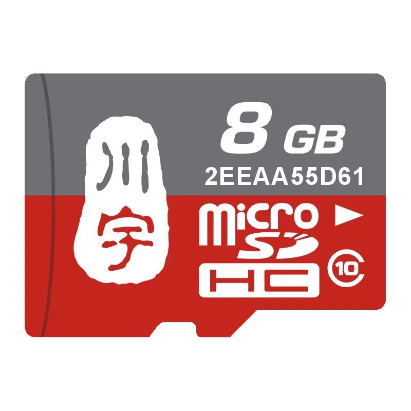
To make your NanoPi NEO boot and run fast we highly recommand you use a Class10 8GB SDHC TF card or a better one. The following cards are what we used in all our test cases presented here:
- SanDisk TF 8G Class10 Micro/SD TF card:
- SanDisk TF128G MicroSDXC TF 128G Class10 48MB/S:
- 川宇 8G C10 High Speed class10 micro SD card:
4.3 Make an Installation TF Card
4.3.1 Get Image Files
Visit this link download link to download image files and the flashing utility:
Image Files nanopi-neo-core-qte-sd4g.img.zip UbuntuCore with Qt-Embedded Image File Flash Utility: win32diskimager.rar Windows utility for flashing Debian image. Under Linux users can use "dd"
4.3.2 Make UbuntuCore with Qt Embedded Image Card
- Uncompress the nanopi-neo-core-qte-sd4g.img.zip and win32diskimager.rar files. Insert a TF card(at least 4G) into a Windows PC and run the win32diskimager utility as administrator. On the utility's main window select your TF card's drive, the wanted image file and click on "write" to start flashing the TF card.
5 Work with Ubuntu-Core with Qt-Embedded
5.1 Run Ubuntu-Core with Qt-Embedded
- Insert a TF card with UbuntuCore image files into your NanoPi NEO, connect the board to a 5V/2A power source the board will be automatically powered on. If you can see the blue LED flashing it means your board is working and UbuntuCore is being loaded.
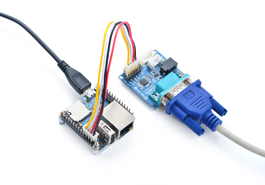
- If you want to do kernel development you need to use a serial communication board, ie a PSU-ONECOM board, which will allow you to operate the board via a serial terminal.
- Here is a setup where we connect a NanoPi M1 to a PC via the PSU-ONECOM and you can power on your M1 from either the PSU-ONECOM or the board's MicroUSB:
- The password for "root" is "fa".
- Update packages
sudo apt-get update
5.2 Ethernet Connection
If the NanoPi NEO is connected to a network via Ethernet before it is powered on it will automatically obtain an IP after it is powered up. If it is not connected via Ethernet or its DHCP is not activated obtaining an IP will fail and system will hang on for about 15 to 60 seconds.
5.3 Login via SSH
The NanoPi NEO doesn't have a video output interface. You can log into the board via SSH. In our test the IP address detected by our router was 192.168.1.230 and we ran the following command to log into the NanoPi NEO:
ssh root@192.168.1.230
The password is fa。
5.4 扩展TF卡文件系统
强烈建议做好系统运行卡之后立即进行文件系统 rootfs 分区的扩展,这将大大提升系统的性能,避免空间不足带来的各种繁琐问题。
- 方法1: 在PC机上扩展TF卡的文件系统 rootfs 分区:
sudo umount /dev/sdx?
sudo parted /dev/sdx unit % resizepart 2 100 unit MB print
sudo resize2fs -f /dev/sdx2
/dev/sdx请替换为实际的TF卡设备文件名。
- 方法2: 在NEO上扩展TF卡的文件系统 rootfs 分区,在NEO上运行Ubuntu-Core,然后执行命令:
sudo fs_resize根据提示,输入 y 开始扩展文件系统,然后再输入 y 选择重启NEO。重启后执行下列命令查看新分区大小:
df -h
5.5 连接USB WiFi
系统默认已经支持市面上众多常见的USB WiFi,想知道你的USB WiFi是否可用只需将其接在NEO上即可,已测试过的USB WiFi型号如下:
序号 型号 1 RTL8188CUS/8188EU 802.11n WLAN Adapter 2 RT2070 Wireless Adapter 3 RT2870/RT3070 Wireless Adapter 4 RTL8192CU Wireless Adapter 5 小米WiFi mt7601
5.6 查看CPU工作温度
获取当前CPU的温度、运行频率等信息:
cpu_freq
6 如何编译Ubuntu-Core with Qt-Embedded系统
访问此处下载地址的sources目录,下载源码nanopi-H3-bsp。
使用7-Zip工具解压后得到两个目录:lichee和android,也可以从github上克隆lichee源码:
git clone https://github.com/friendlyarm/h3_lichee.git lichee
注:lichee是全志为其CPU的板级支持包所起的项目名称,里面包含了U-boot,Linux等源码和众多的编译脚本。
6.1 编译lichee源码
编译全志 H3 的BSP源码包必须使用64bit的Linux PC系统,并安装下列软件包,下列操作均基于Ubuntu-14.04 LTS-64bit:
sudo apt-get install gawk git gnupg flex bison gperf build-essential \
zip curl libc6-dev libncurses5-dev:i386 x11proto-core-dev \
libx11-dev:i386 libreadline6-dev:i386 libgl1-mesa-glx:i386 \
libgl1-mesa-dev g++-multilib mingw32 tofrodos \
python-markdown libxml2-utils xsltproc zlib1g-dev:i386
编译lichee源码包,进入lichee目录,执行命令:
cd lichee
./build.sh -p sun8iw7p1 -b nanopi-h3
该命令会一次性编译好U-boot、Linux内核和模块。
注:lichee目录里内置了交叉编译器,当使用build.sh脚本进行源码编译时,会自动使用该内置的编译器,所以无需手动安装编译器。
6.2 打包系统组件
./gen_script.sh nanopi-neo该命令会将所有编译生成的可执行文件(包括U-boot、Linux内核)和系统配置文件拷贝到lichee/tools/pack/out/目录以便进行统一管理,并且会该目录下生成
script.bin文件。
script.bin是全志系列 CPU 的硬件板级配置文件,相关信息请查看script.bin。
下列命令可用于更新TF卡上的U-boot:
./fuse_uboot.sh /dev/sdx
/dev/sdx请替换为实际的TF卡设备文件名。
uImage和内核模块均位于linux-3.4/output目录下,将uImage拷贝到TF卡的boot分区的根目录即可更新内核。
6.3 编译U-boot
如果你想单独编译U-boot,可以执行命令:
./build.sh -p sun8iw7p1 -b nanopi-h3 -m uboot
编译生成的可执行文件需打上全志系列CPU的硬件板级配置补丁后才能烧写到TF卡上运行,执行./build.sh pack能自动完成打补丁的操作。
如何手动为U-boot打补丁请查看H3_Manual_build_howto,执行下列命令更新TF卡上的U-boot:
./fuse_uboot.sh /dev/sdx
/dev/sdx请替换为实际的TF卡设备文件名。
6.4 编译Linux内核
如果你想单独编译Linux内核,可以执行命令:
./build.sh -p sun8iw7p1 -b nanopi-h3 -m kernel
编译完成后uImage和内核模块均位于linux-3.4/output目录下,将uImage拷贝到TF卡的boot分区的根目录即可。
6.5 清理lichee源码
./build.sh -p sun8iw7p1_linux -b nanopi-h3 -m clean
7 Resources
- Schematics
- Dimensional Diagram
- H3 Datesheet Allwinner_H3_Datasheet_V1.2.pdf
