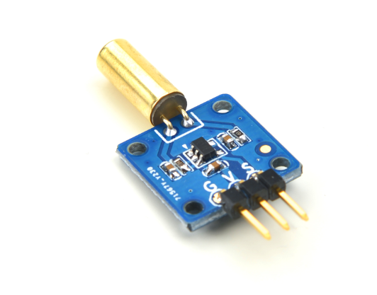
Matrix - Ball Rolling Switch
Contents
1 Introduction
- The Matrix-Ball_Rolling_Switch module is a ball switch. Its electrical characteristics are very similar to a mercury switch's however a mercury switch is easily broken, oxidized, leaking and not environment-friendly. This ball switch prevents all these issues.
- The switch is free to move any angle and if that angle is between 15 degrees and 45 degrees a signal will be generated and used as an input to a Schmitt trigger.
2 Features
- GPIO
- Small
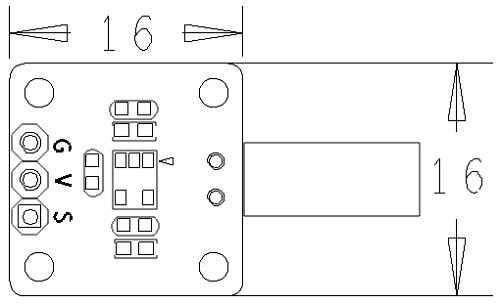
- 2.54 mm spacing pin header
- PCB Dimension(mm):16 x 16
- Pin Description:
| Pin | Description |
| S | Digital GPIO |
| V | Supply Voltage 5V |
| G | Ground |
3 Basic Device Operation
Please connect Pin V to a power supply, Pin G grounded and Pin S to a digital output. When you move the switch pushing the internal metal ball to connect the trigger point a high level signal will be generated and output to a Schmitt trigger which reverses this signal to output a low level signal. When you move the switch pushing the internal metal ball away from the trigger point a low level signal will be generated and output to a Schmitt trigger which reverses this signal to output a high level signal.
4 Applications
4.1 Connect to NanoPi M1
Please refer to the following connection diagram to connect the module to the NanoPi M1:
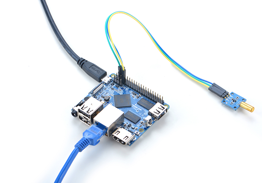
Connection Details:
| Matrix-Ball_Rolling_Switch | NanoPi M1 |
| S | Pin7 |
| V | Pin4 |
| G | Pin6 |
4.2 Connect to NanoPi 2
Please refer to the following connection diagram to connect the module to the NanoPi 2:
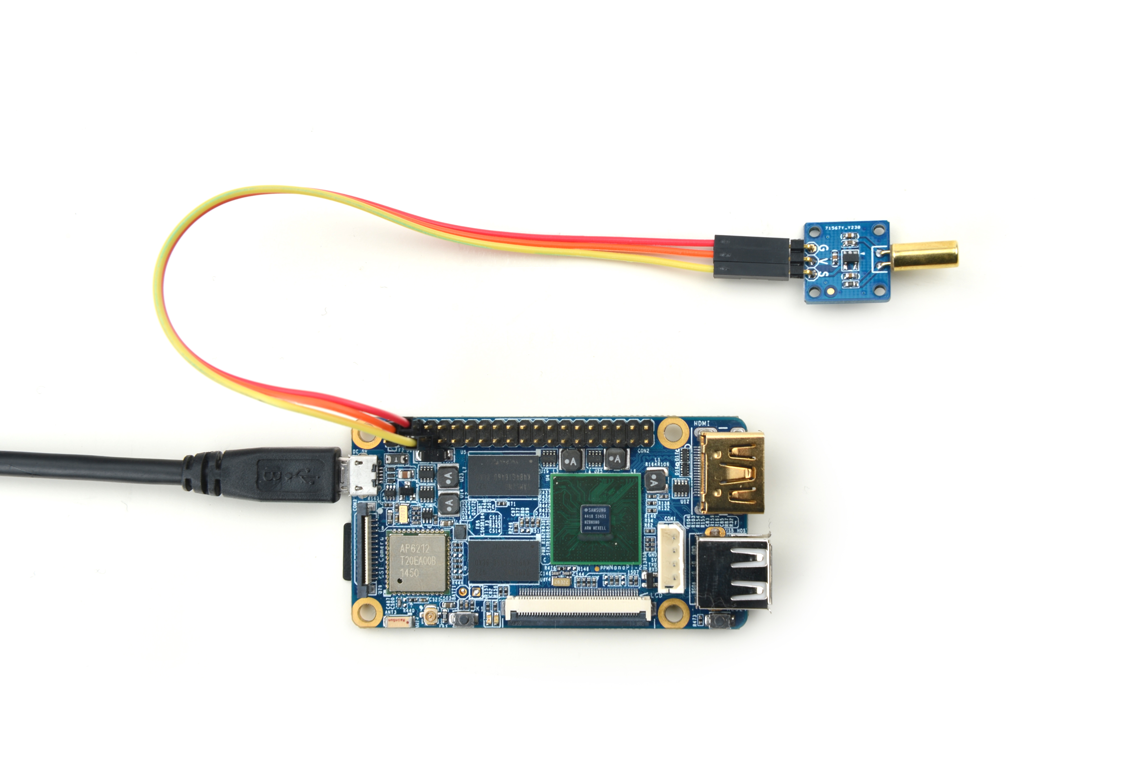
Connection Details:
| Matrix-Ball_Rolling_Switch | NanoPi 2 |
| S | Pin7 |
| V | Pin4 |
| G | Pin6 |
4.3 Connect to NanoPi M2 / NanoPi 2 Fire
Please refer to the following connection diagram to connect the module to the NanoPi M2/ NanoPi 2 Fire.
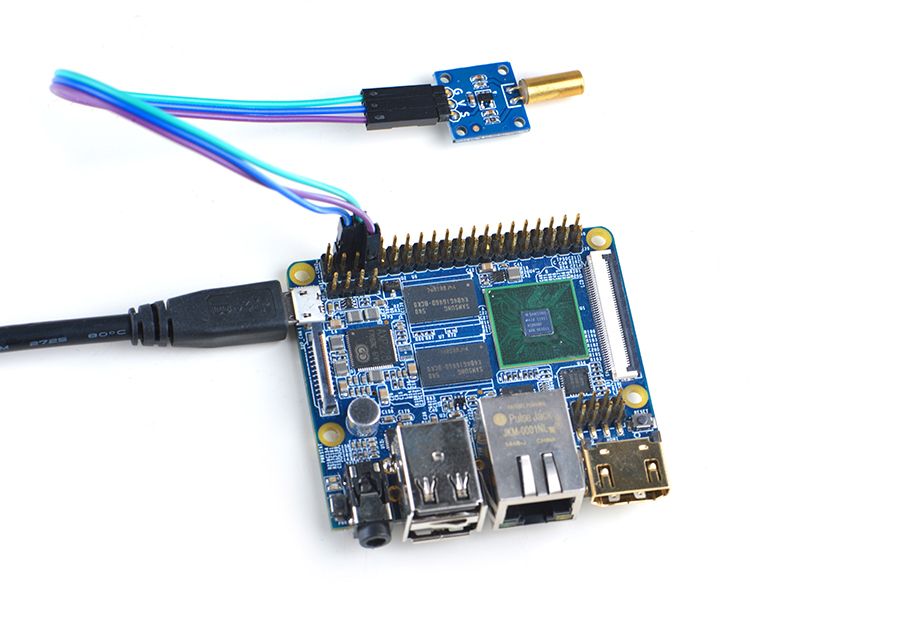
Connection Details:
| Matrix-Ball_Rolling_Switch | NanoPi M2 |
| S | Pin7 |
| V | Pin4 |
| G | Pin6 |
4.4 Connect to NanoPC-T2
Please refer to the following connection diagram to connect the module to the NanoPC-T2:
Matrix-Ball_Rolling_Switch_NanoPC-T2
Connection Details:
| Matrix-Ball_Rolling_Switch | NanoPC-T2 |
| S | Pin15 |
| V | Pin29 |
| G | Pin30 |
5 Compile & Run Test Program
Boot your ARM board with Debian and copy the matrix code:
$ apt-get update && apt-get install git
$ git clone https://github.com/friendlyarm/matrix.git
If your cloning is done successfully a "matrix" directory will be generated.
Compile and install Matrix:
$ cd matrix
$ make && make install
Run test program:
$ matrix-gpio_intNote: this module is not plug and play therefore before running the module please make sure it is connected to an ARM board.
Here is what you should observe:
Waiting event...
Device[0] value is 1
When you tilt the module, roll the ball and make it touch the trigger point you will see an event is detected.
6 Code Sample
所有的开发板都共用一套Matrix代码,本模块的测试示例代码为matrix-gpio_int,内容如下:
int main(int argc, char ** argv)
{
    int i, board;
    int retSize = -1;
    char value[ARRAY_SIZE(dev)];

    if ((board = boardInit()) < 0)
        printf("Fail to init board\n");

    if (argc == 2) {
        dev[0].pin = atoi(argv[1]);
    }
    printf("Using GPIO_PIN(%d)\n", dev[0].pin);
    system("modprobe "DRIVER_MODULE);
    signal(SIGINT, intHandler);
    if (board == BOARD_NANOPI_T2)
        dev[0].pin = GPIO_PIN(15);
    if ((devFD =sensorInit(dev, ARRAY_SIZE(dev))) == -1) {
        printf("Fail to init sensor\n");
        return -1;
    }
    printf("Waiting event...\n");
    if ((retSize = sensorRead(devFD, value, ARRAY_SIZE(dev))) == -1) {
        printf("Fail to read sensors\n");
    }
    if (retSize > 0) {
        i = 0;
        for (i=0; i<retSize; i++) {
            printf("dev[%d] value: %d\n", i, value[i]);
        }
    }
    sensorDeinit(devFD);
    system("rmmod "DRIVER_MODULE);
    return 0;
}
API说明参考维基:Matrix API reference manual
7 Resources
- [Schematic](Matrix - Ball Rolling Switch-Schematic.pdf)
8 Update Log
8.1 Feb-24-2016
- Added the driver's source code location in Section 5.2
