NanoPi 2
Contents
1 Introduction
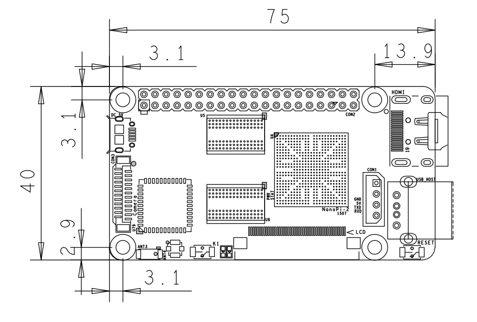
- The NanoPi2 is a high performance ARM Board developed by FriendlyARM for Hobbysts, Makers and Hackers for IOT projects. It features Samsung’s Cortex-A9 Quad Core S5P4418@1.4GHz SoC and 1G 32bit DDR3 RAM. It has built-in WiFi and Bluetooth which supports 802.11 b/g/n and Bluetooth 4.0. It boots Android and Debian from a TF card. It integrates an HDMI and LCD interface. Its adoption of the Raspberry Pi’s GPIO pin header makes it compatible with both Raspberry Pi’s external GPIO modules and Arduino’s shield boards. Its PCB dimension is 75 x 40 mm.
2 Features
- CPU: S5P4418, 1.4GHz
- RAM: 1GB DDR3
- Built in SDIO WiFi and Bluetooth module
- USB 2.0 Type A x 1
- Debug Serial Port/UART0 x 1
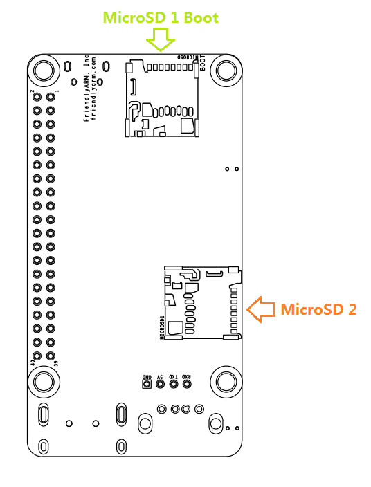
- microSD Slot x 2
- microUSB x 1: for data transmission and power input
- LCD Interface: 0.5mm spacing FPC socket, full color LCD (RGB:8-8-8)
- HDMI: HDMI 1.4A, Type-A, 1080P60
- DVP Camera Interface: 0.5mm spacing FPC socket. It includes ITU-R BT 601/656 8-bit, I2C and IO
- GPIO: 2.54mm spacing 40pin, compatible with Raspberry Pi's GPIO. It includes UART, SPI, I2C, IO etc
- Button: User Button x 1, Reset Button x 1
- LED: LED for Power Indication x 1, User LED x 1
- PCB 尺寸: 75 x 40mm
- Power: DC 5V/2A
- OS: Android, Debian
3 接口布局和尺寸
3.1 接口布局
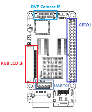
- GPIO1管脚定义
Pin# Name Pin# Name 1 VDD_SYS_3.3V 2 VDD_5V 3 I2C0_SDA 4 VDD_5V 5 I2C0_SCL 6 DGND 7 GPIOB28 8 UART3_TXD 9 DGND 10 UART3_RXD 11 GPIOB29 12 GPIOB26 13 GPIOB30 14 DGND 15 GPIOB31 16 PWM2 17 VDD_SYS_3.3V 18 GPIOB27 19 SPI0_MOSI 20 DGND 21 SPI0_MISO 22 PWM0 23 SPI0_CLK 24 SPI0_CS 25 DGND 26 PWM1 27 I2C1_SDA 28 I2C1_SCL 29 GPIOC8 30 DGND 31 SPI2_CLK 32 GPIOC28 33 SPI2_CS 34 DGND 35 SPI2_MOSI 36 GPIOC7 37 SPI2_MISO 38 ALIVEGPIO2 39 DGND 40 ALIVEGPIO3
- Debug Port CON1(UART0)
Pin# Name 1 DGND 2 VDD_5V 3 TXD0 4 RXD0
- DVP Camera IF 管脚定义
Pin# Name 1, 2 VDD_SYS_3.3V 7,9,13,15,24 DGND 3 SCL0 4 SDA0 5 GPIOB14 6 GPIOB16 8,10 NC 11 VSYNC 12 HREF 14 PCLK 16-23 Data bit7-0
- RGB LCD IF 管脚定义
Pin# Name 1, 2 VDD_5V 11,20,29, 37,38,39,40, 45 DGND 3-10 Blue LSB to MSB 12-19 Green LSB to MSB 21-28 Red LSB to MSB 30 GPIOB25 31 GPIOC15 32 XnRSTOUT Form CPU 33 VDEN 34 VSYNC 35 HSYNC 36 LCDCLK 41 SCL2 42 SDA2 43 GPIOC16 44 NC
- 说明
- VDD_SYS_3.3V: 3.3V电源输出
- VDD_5V: 5V电源输入/输出。当电压大于MicroUSB时,向板子供电,否则板子从MicroUSB取电。输入范围:4.7~5.6V。
- 更详细的信息请查看原理图:NanoPi-2-1507-Schematic.pdf
3.2 机械尺寸
4 快速入门
4.1 准备工作
要开启你的NanoPi新玩具,请先准备好以下硬件
- NanoPi 2 主板
- microSD卡/TF卡: Class10或以上的 8GB SDHC卡
- microUSB线
- 一台运行Linux的电脑,需要联网,建议使用Ubuntu 14.04 64位系统
4.2 制作一张带运行系统的microSD卡
- 1) 将microSD插入Ubuntu的电脑,用以下命令查看你的SD卡设备名
dmesg | tail
当dmesg输出类拟信息 sdc: sdc1 sdc2时,则表示SD卡对应的设备名为 /dev/sdc,也通过用命令cat /proc/partitions来查看。
- 2) 下载Linux下的制作包
git clone https://github.com/friendlyarm/sd-fuse_nanopi2.git
cd sd-fuse_nanopi2
- 3) 制作启动Android的SD卡
su
./fusing.sh /dev/sdx
(注:/dev/sdx请替换为实际的SD卡设备文件名)
制作包中未包含Android和Debian的烧写文件,第一次使用时会提示需要下载,输入Y下载,N或10秒未输入则取消。
- 4) 制作启动Debian的SD卡
./fusing.sh /dev/sdx debian
4.3 运行Android
将制作好包含Android的microSD卡插入NanoPi2,连接HDMI,最后连接电源(5V 2A),NanoPi2会上电自动开机,看到板上的蓝色LED亮,这说明系统已经开始启动了,同时电视上也将能看到Android启动的画面。
如果您连接了串口,则还可以通过PC的minicom看到系统启动的调试信息。
5 如何编译系统
5.1 抢建开发环境
5.2 安装交叉编译器
编译U-Boot和Linux可以直接使用Android源代码中的提供的交叉编译器,假设您的Android源代码已下载好,可以通过设置环境PATH来使用它:
export PATH=/opt/FriendlyARM/s5p4418/android/prebuilts/gcc/linux-x86/arm/arm-eabi-4.6/bin:$PATH
arm-eabi-gcc -v
其中“/opt/FriendlyARM/s5p4418/android”是Android源代码目录。
使用Android中的交叉编译器时,编译U-Boot和Linux应指定 CROSS_COMPILE=arm-eabi- 。
5.3 编译U-Boot
下载U-Boot源代码并编译,注意分支是s5p4418-nanopi2:
git clone https://github.com/friendlyarm/uboot_nanopi2.git
cd uboot_nanopi2
git checkout s5p4418-nanopi2
make s5p4418_nanopi2_config
make CROSS_COMPILE=arm-eabi-
编译成功结束后您将获得u-boot.bin,您可以通过fastboot来更新正在运行的NanoPi2板上SD的U-Boot。
注意:您不能直接使用dd来更新SD卡,否则有可能会导致无法正常启动。
5.4 准备mkimage
编译内核需要用到U-Boot中的工具mkimage,因此,在编译内核uImage前,您需要保证您的主机环境可以成功运行它。
你可以直接使用命令 sudo apt-get install u-boot-tools 来安装,也可以自己编译并安装:
cd uboot_nanopi2
make tools
mkdir -p /usr/local/sbin && cp -v tools/mkimage /usr/local/sbin
5.5 编译Linux kernel
5.5.1 编译内核
- 下载内核源代码
git clone https://github.com/friendlyarm/linux-3.4.y.git
cd linux-3.4.y
git checkout s5p4418-nanopi2
NanoPi2内核所属的分支是s5p4418-nanopi2,在开始编译前先切换分支。
- 编译Android内核
make nanopi2_android_defconfig
touch .scmversion
make CROSS_COMPILE=arm-eabi- uImage
- 编译Debian内核
make nanopi2_linux_defconfig
touch .scmversion
make CROSS_COMPILE=arm-eabi- uImage
编译成功结束后,新生成的内核烧写文件为 arch/arm/boot/uImage 。
5.5.2 编译内核模块
Android包含内核模块,位于system分区的 /lib/modules/ 下,如果您有新的内核模块或者内核配置有变化,则需要重新编译。
首先编译内核源代码中的模块:
cd linux-3.4.y
make CROSS_COMPILE=arm-eabi- modules
另外有2个内核模块的源代码位于Android源代码中,可使用以下命令来编译:
cd /opt/FriendlyARM/s5p4418/android
./vendor/friendly-arm/build/common/build-modules.sh
其中 “/opt/FriendlyARM/s5p4418/android” 是指Android源代码的TOP目录,使用参数“-h”可查看帮助。
编译成功结束后,会显示生成的内核模块。
5.6 编译Android
- 搭建编译环境
搭建编译Android的环境建议使用64位的Ubuntu 14.04,安装需要的包即可。
sudo apt-get install zlib1g-dev:i386
sudo apt-get install bison g++-multilib git gperf libxml2-utils make python-networkx zip
sudo apt-get install flex libncurses5-dev zlib1g-dev gawk minicom
更多说明可查看 https://source.android.com/source/initializing.html 。
- 下载源代码
Android源代码的下载需要使用repo,其安装和使用请查看 https://source.android.com/source/downloading.html 。
mkdir android && cd android
repo init -u git@github.com:friendlyarm/android_manifest.git -b nanopi2-kitkat
repo sync
其中“android”是指工作目录,另外,初始化repo时也可以使用HTTPS clone URL。
- 编译系统
source build/envsetup.sh
lunch aosp_nanopi2-userdebug
make -j8
编译成功完成后,目录 out/target/product/nanopi2/ 下包含可用于烧写的image文件。
6 Resources
- [Schematic]( NanoPi-2-1507-Schematic.pdf)
- [Dimensions]( NanoPi-2-1507-Dimesions(dxf).zip )
- For more details please refer to the document:NanoPi-2-1507-Dimesions(dxf).zip


