NanoPi NEO2 Black/zh
From FriendlyELEC WiKi
Revision as of 09:08, 16 October 2019 by Wuweidong (Talk | contribs) (Created page with "English ==Introduction== Overview File:NanoPi_NEO2_Black-2.jpg|thumb|frameless|250x250px|Fr...")
Contents
1 Introduction
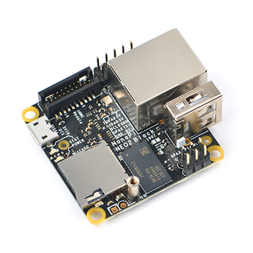
- The NanoPi NEO2 Black is another fun board developed by FriendlyELEC for makers, hobbyists and fans.
2 Hardware Spec
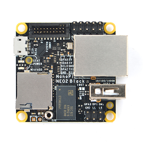
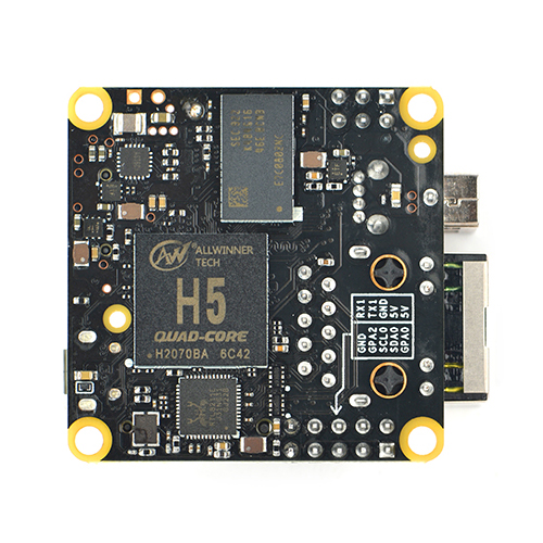
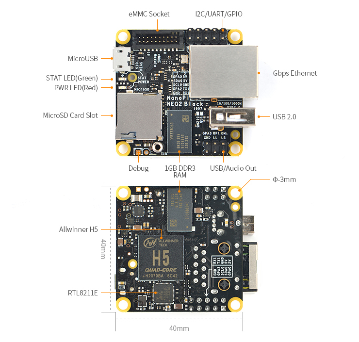
- CPU: Allwinner H5, Quad-core 64-bit high-performance Cortex A53
- DDR3 RAM: 512MB/1GB
- Flash: no onboard Flash, but one eMMC flash module socket
- Connectivity: 10/100/1000M Ethernet, RTL8211E-VB-CG chip
- USB Host: USB Type A x 1 and USB pin header x 1
- MicroSD Slot: MicroSD x 1 for system boot and storage
- LED: Power LED x 1, System LED x 1
- GPIO1: 2.54mm pitch 10 pin-header, includes UART, I2C, IO, 5VIN/(or OUT)etc
- GPIO2: 2.54mm pitch 6 pin-header, includes USB, line out, IO etc
- Serial Debug Port: 2.54mm pitch 2pin-pads, 115200bps
- Audio: line out on GPIO2
- MicroUSB: Power input(5V/2A) and OTG
- PCB Dimension: 40 x 40mm
- Working Temperature: -20℃ to 70℃
- Weight: 16.37g
- OS/Software: u-boot,Ubuntu Core
3 Software Features
4 Diagram, Layout and Dimension
4.1 Layout
- GPIO1(I2C/UART/GPIO)
Pin# Name Linux gpio Pin# Name Linux gpio 1 GPIOA0 0 2 5V in or out - 3 I2C_SDA0 - 4 5V in or out - 5 I2C_SCL0 - 6 GND - 7 GPIOA2 2 8 UART1_TX - 9 GND - 10 UART1_RX -
- GPIO2(USB/Audio OUT)
Pin# Name Linux gpio Pin# Name Linux gpio 1 Line out Right - 2 USB DM - 3 Line out Left - 4 USB DP - 5 GND - 6 GPIOA3 3
- eMMC Module Socket Pinout
Pin# Name Pin# Name 1 EMMC_D0 2 EMMC_D1 3 EMMC_D2 4 EMMC_D3 5 EMMC_D4 6 EMMC_D5 7 EMMC_D6 8 EMMC_D7 9 N/C 10 GND 11 EMMC_CMD 12 EMMC_CLK 13 N/C 14 GND 15 N/C 16 3.3V OUT 17 eMMC_RST 18 3.3V OUT 19 GND 20 GND
- Note:
- For more details refer to the document: NanoPi_NEO2_Black_1907_Schematic.pdf
4.2 Dimensional Diagram
- For more details refer to the document: pcb file in dxf format


