Template:FriendlyCoreAllwinnerH3
Contents
1 Connect to USB Camera(FA-CAM202)
The FA-CAM202 is a 200M USB camera. Connect your board to camera module. Then boot OS, connect your board to a network, log into the board as root and run "mjpg-streamer":
$ cd /root/mjpg-streamer
$ make
$ ./start.sh
You need to change the start.sh script and make sure it uses a correct /dev/videoX node. You can check your camera's node by running the following commands:
$ apt-get install v4l-utils
$ v4l2-ctl -d /dev/video0 -D
Driver Info (not using libv4l2):
        Driver name   : uvcvideo
        Card type     : HC 3358+2100: HC 3358+2100  / USB 2.0 Camera: USB 2.0 Camera
        Bus info      : usb-1c1b000.usb-1
	...
The above messages indicate that "/dev/video0" is camera's device node.The mjpg-streamer application is an open source video steam server. After it is successfully started the following messages will be popped up:
$ ./start.sh
 i: Using V4L2 device.: /dev/video0
 i: Desired Resolution: 1280 x 720
 i: Frames Per Second.: 30
 i: Format............: YUV
 i: JPEG Quality......: 90
 o: www-folder-path...: ./www/
 o: HTTP TCP port.....: 8080
 o: username:password.: disabled
 o: commands..........: enabled
start.sh runs the following two commands:
export LD_LIBRARY_PATH="$(pwd)"
./mjpg_streamer -i "./input_uvc.so -d /dev/video0 -y 1 -r 1280x720 -f 30 -q 90 -n -fb 0" -o "./output_http.so -w ./www"
Here are some details for mjpg_streamer's major options:
-i: input device. For example "input_uvc.so" means it takes input from a camera;
-o: output device. For example "output_http.so" means the it transmits data via http;
-d: input device's subparameter. It defines a camera's device node;
-y: input device's subparameter. It defines a camera's data format: 1:yuyv, 2:yvyu, 3:uyvy 4:vyuy. If this option isn't defined MJPEG will be set as the data format;
-r: input device's subparameter. It defines a camera's resolution;
-f: input device's subparameter. It defines a camera's fps. But whether this fps is supported depends on its driver;
-q: input device's subparameter. It defines the quality of an image generated by libjpeg soft-encoding;
-n: input device's subparameter. It disables the dynctrls function;
-fb: input device's subparameter. It specifies whether an input image is displayed at "/dev/fbX";
-w: output device's subparameter. It defines a directory to hold web pages;
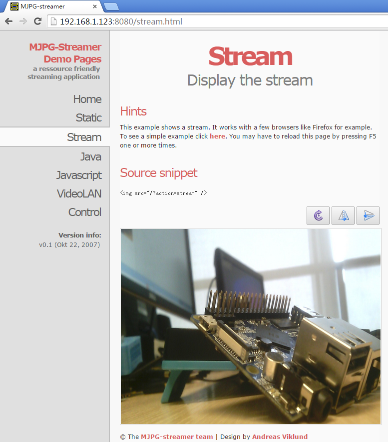
In our case the board's IP address was 192.168.1.230. We typed 192.168.1.230:8080 in a browser and were able to view the images taken from the camera's. Here is what you would expect to observe:

2 Check CPU's Working Temperature
You can get CPU's working temperature by running the following command:
$ cpu_freq
CPU0 online=1 temp=26581 governor=ondemand cur_freq=480000
CPU1 online=1 temp=26581 governor=ondemand cur_freq=480000
CPU2 online=1 temp=26581 governor=ondemand cur_freq=480000
CPU3 online=1 temp=26581 governor=ondemand cur_freq=480000
This message means there are currently four CPUs working. All of their working temperature is 26.5 degree in Celsius and each one's clock is 480MHz.
3 Test Infrared Receiver
Note: Please Check your board if IR receiver exist.
By default the infrared function is disabled you can enable it by using the npi-config utility:
$ npi-config
    6 Advanced Options     Configure advanced settings
        A8 IR              Enable/Disable IR
            ir Enable/Disable ir[enabled]
Reboot your system and test its infrared function by running the following commands:
$ apt-get install ir-keytable
$ echo "+rc-5 +nec +rc-6 +jvc +sony +rc-5-sz +sanyo +sharp +mce_kbd +xmp" > /sys/class/rc/rc0/protocols   # Enable infrared
$ ir-keytable -t
Testing events. Please, press CTRL-C to abort.
"ir-keytable -t" is used to check whether the receiver receives infrared signals. You can use a remote control to send infrared signals to the receiver. If it works you will see similar messages as follows:
1522404275.767215: event type EV_MSC(0x04): scancode = 0xe0e43
1522404275.767215: event type EV_SYN(0x00).
1522404278.911267: event type EV_MSC(0x04): scancode = 0xe0e42
1522404278.911267: event type EV_SYN(0x00).
4 Access GPIO Pins/Wirings with WiringNP
The wiringPi library was initially developed by Gordon Henderson in C. It contains libraries to access GPIO, I2C, SPI, UART, PWM and etc. The wiringPi library contains various libraries, header files and a commandline utility:gpio. The gpio utility can be used to read and write GPIO pins.
FriendlyElec integrated this utility in FriendlyCore system allowing users to easily access GPIO pins. For more details refer to WiringNP WiringNP
5 Run Qt Demo
Run the following command
$ sudo /opt/QtE-Demo/run.sh
Here is what you expect to observe. This is an open source Qt Demo:
