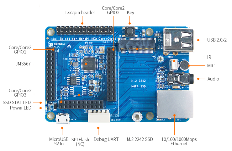
Mini Shield for NanoPi NEO Core/Core2
Contents
1 Introduction
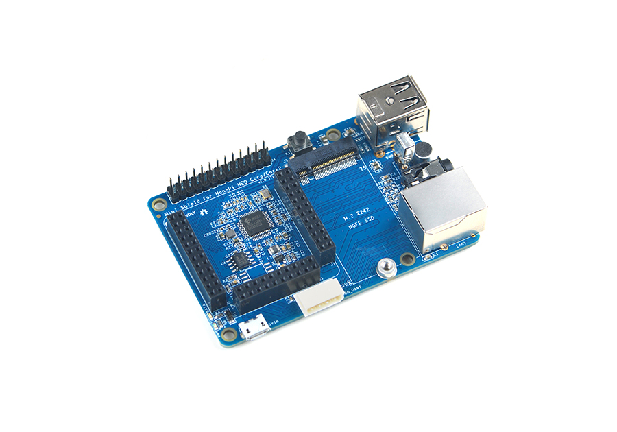
- The Mini Shield for NanoPi NEO Core/Core2 is a custom SDK carrier board developed for the NanoPi NEO Core and NanoPi NEO Core2. It has Ethernet port, serial debug port, audio, USB port and etc.
- 1 x Onboard JMS567 USB to SATA IC and 1 x M.2 SSD interface for connecting a 2242 SSD.
- 2 x USB Host ports.
- 1 x Serial debug port for connecting a serial communication board and 1 x Ethernet port.
- 1 x Onboard Microphone and 1 x 3.5mm audio jack for audio recording and playing.
- 2 x 13 Pin header which populate the NanoPi NEO Core/Core2's IO pins.
- 1 x button and 1 x IR interface for working with a remote control
- Room for an SPI Flash(SOP8-200mil) is reserved. Users can solder an SPI flash on the board.
- It has the same dimension and mounting holes as those of a Raspberry Pi. The whole board can be well fit into a RPi's case
2 Hardware Spec
- Same form factor as RPi, can be well fit into a RPi's case
- 2 x USB Host
- 1 x Serial debug port and 1 x Ethernet port
- 1 x audio input and 1 x audio output
- 2 x 13 Pin GPIO pin-header
- 1 x Button
- 1 x M.2 2242 SSD interface
- 1 x IR receiver interface
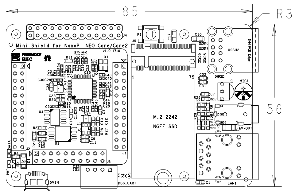
- PCB dimension(mm): 85 x 56
2.1 Layout
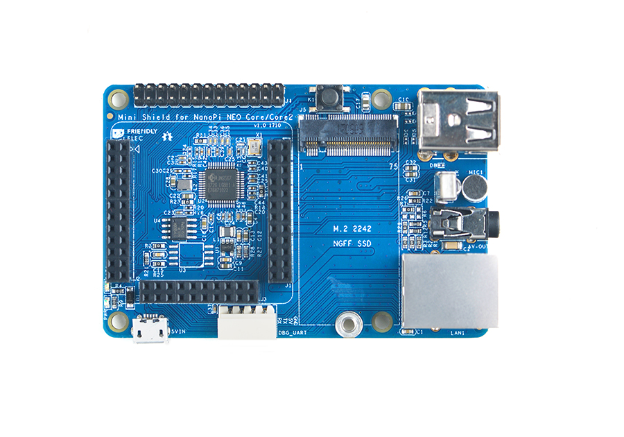
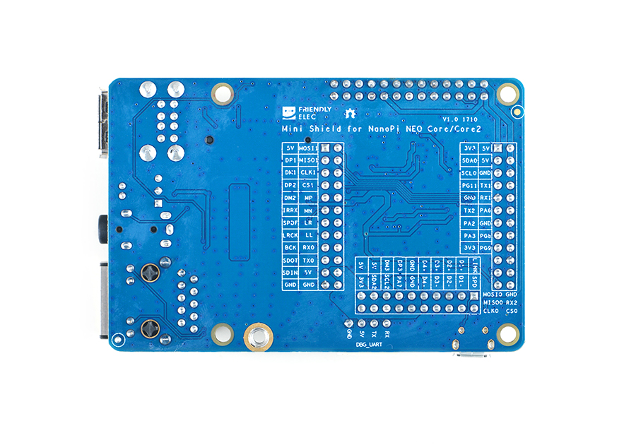
The Mini Shield for NanoPi NEO Core/Core2's layout of interface and connectors is shown on the right. On its back there are silkscreens of description for the connectors and pins.
When you mount a NanoPi NEO Core or NanoPi NEO Core2 to a Mini Shield be aware of the Core/Core2's mounting position. Each pin-header's first pin is marked as a triangle.
- 2x13 Pin header Pin Description
Number# Name Number# Name 1 SYS_3.3V 2 VDD_5V 3 I2C0_SDA / GPIOA12 4 VDD_5V 5 I2C0_SCL / GPIOA11 6 GND 7 GPIOG11 8 UART1_TX / GPIOG6 9 GND 10 UART1_RX / GPIOG7 11 UART2_TX / GPIOA0 12 GPIOA6 13 UART2_RTS / GPIOA2 14 GND 15 UART2_CTS / GPIOA3 16 UART1_RTS / GPIOG8 17 SYS_3.3V 18 UART1_CTS / GPIOG9 19 SPI1_MOSI/GPIOA15 20 GND 21 SPI1_MISO/GPIOA16 22 UART2_RX / GPIOA1 23 SPI1_CLK/GPIOA14 24 SPI1_CS / GPIOA13 25 GND 26 SPDIF-OUT/GPIOA17
3 Hardware Setup
A NanoPi NEO Core or NanoPi NEO Core2 can be mounted on a Mini Shield for NanoPi NEO Core/Core2. Here is a hardware setup:
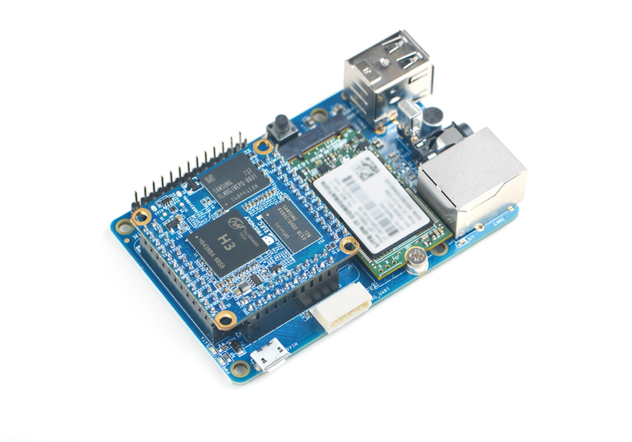
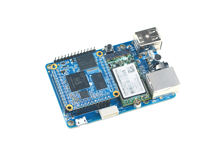
It is convenient to connect a USB device and network to a Mini Shield for NanoPi NEO Core/Core2
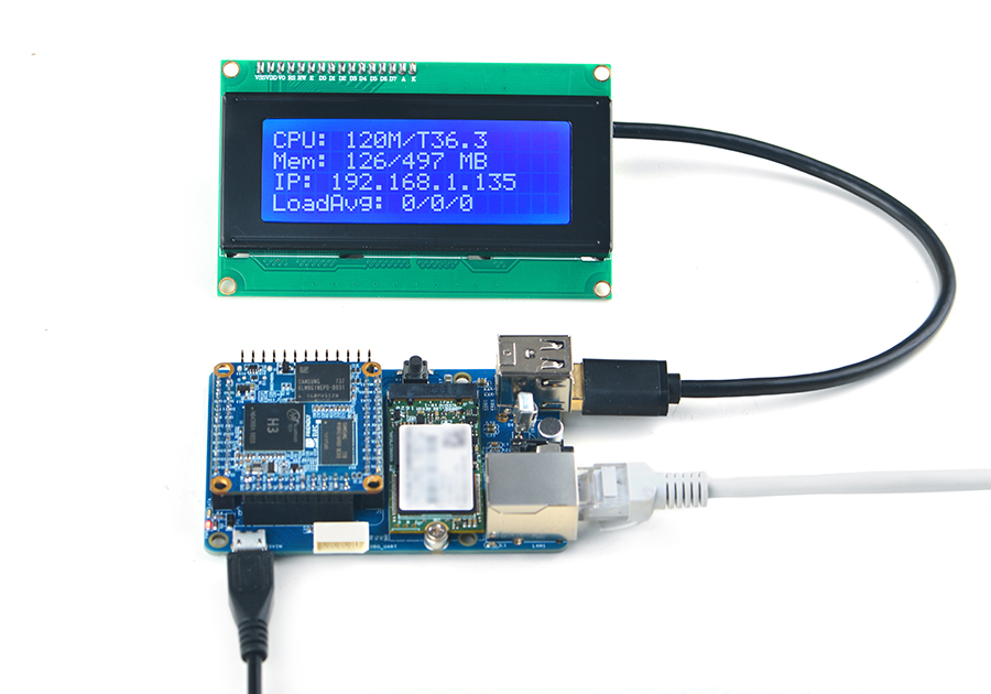
A Mini Shield for NanoPi NEO Core/Core2 can be well fit into a RPi's case:
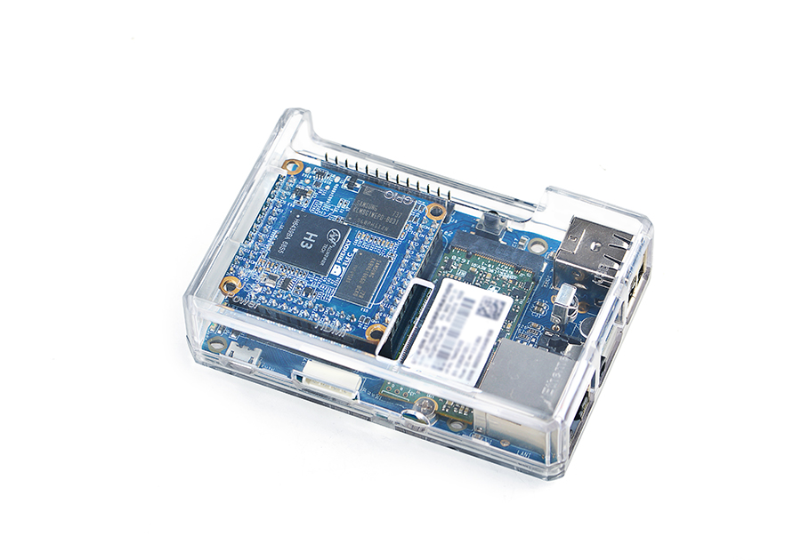
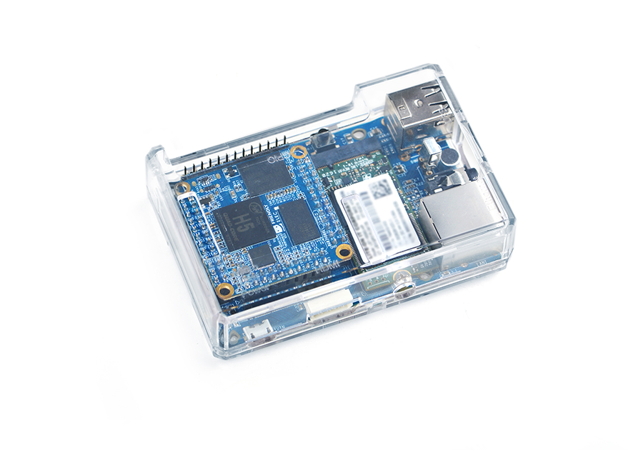
4 Application
4.1 1. M.2 2242 SSD Interface
Insert an SSD hard drive to the M.2 2242 interface. After system is booted you can check the SSD device by running the following command:
fdisk -l
Here is what you expect to see:

4.2 2. Boot OS from SSD
You can boot a NanoPi NEO Core or Core2 from an SSD hard driver inserted in a Mini Shield for NanoPi NEO Core/Core2. This way of booting an OS has the following advantages:
1) faster read/write;
2) an SSD has much longer life than a TF card;
3) more reliable than booting from a TF card;
You can install an OS to an SSD hard drive by using the npi-config utility. Here is a command to start the npi-config utility:
sudo npi-config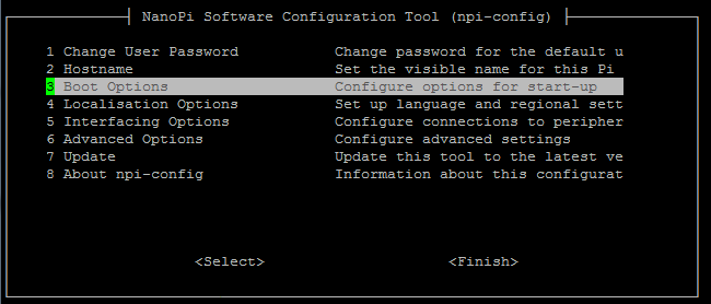
After the utility shows the "Boot Options" menu select "Boot device" and you will see the following two options:
1) D1 Hard drive
2) D2 TF card

Select "D1 Hard drive" to boot from an SSD hard drive.
If you want to boot an OS from a TF card you need to select "D2 TF card".
If your npi-config utility doesn't have "Boot device" on its menu you may need to update your npi-config utility by running the "Update" function on the menu.
4.3 3. Audio Input & Output
1. Audio Recording:
arecord -D hw:0,0 -f cd test.wav
Here is what you expect to see:
![]()
2. Audio Playing with the following command e.g. playing a "/root/Music/test.wav" file
aplay /root/Music/test.wav
Here is what you expect to see:

可以使用alsamixer工具调节播放音乐的音量
