Mini Shield for NanoPi NEO Core/Core2
Contents
[hide]1 Introduction
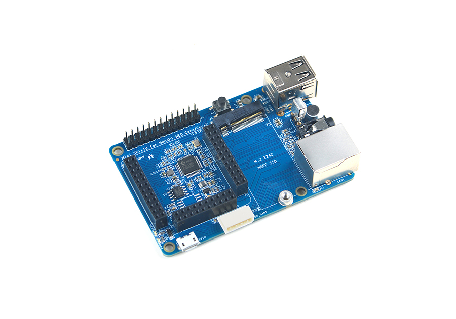
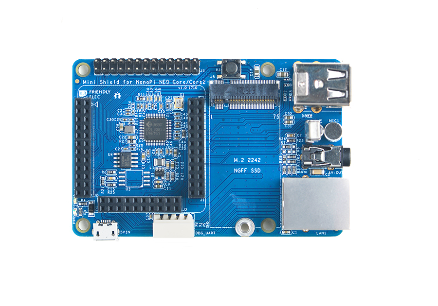
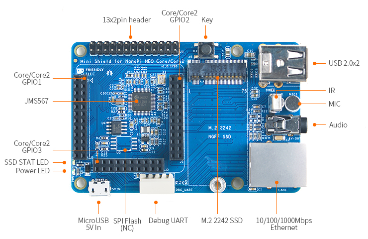
- The Mini Shield for NanoPi NEO Core/Core2 is a custom SDK carrier board developed for the NanoPi NEO Core and NanoPi NEO Core2. It has Ethernet port, serial debug port, audio, USB port and etc.
- 1 x Onboard JMS567 USB to SATA IC and 1 x M.2 SSD interface for connecting a 2242 SSD.
- 2 x USB Host ports.
- 1 x Serial debug port for connecting a serial communication board and 1 x Ethernet port.
- 1 x Onboard Microphone and 1 x 3.5mm audio jack for audio recording and playing.
- 2 x 13 Pin header which populate the NanoPi NEO Core/Core2's IO pins.
- 1 x button and 1 x IR interface for working with a remote control
- Room for an SPI Flash(SOP8-200mil) is reserved. Users can solder an SPI flash on the board.
- It has the same dimension and mounting holes as those of a Raspberry Pi. The whole board can be well fit into a RPi's case
2 Hardware Spec
- Same form factor as RPi, can be well fit into a RPi's case
- 2 x USB Host
- 1 x Serial debug port and 1 x Ethernet port
- 1 x audio input and 1 x audio output
- 2 x 13 Pin GPIO pin-header
- 1 x Button
- 1 x M.2 2242 SSD interface
- 1 x IR receiver interface
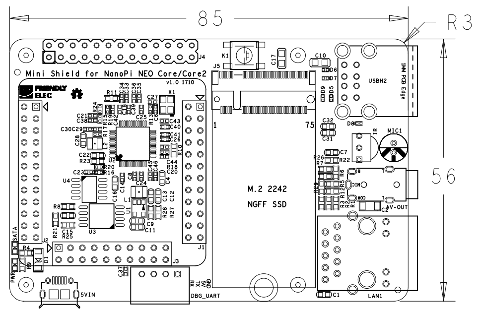
- PCB dimension(mm): 85 x 56
2.1 Layout
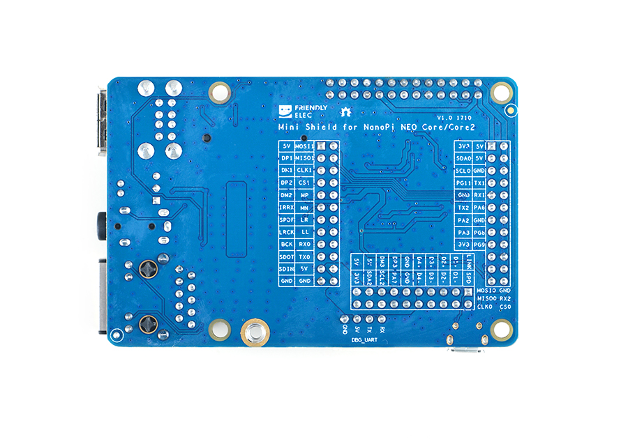
The Mini Shield for NanoPi NEO Core/Core2's layout of interface and connectors is shown on the right. On its back there are silkscreens of description for the connectors and pins.
When you mount a NanoPi NEO Core or NanoPi NEO Core2 to a Mini Shield be aware of the Core/Core2's mounting position. Each pin-header's first pin is marked as a triangle.
- 2x13 Pin header Pin Description
Number# Name Number# Name 1 SYS_3.3V 2 VDD_5V 3 I2C0_SDA / GPIOA12 4 VDD_5V 5 I2C0_SCL / GPIOA11 6 GND 7 GPIOG11 8 UART1_TX / GPIOG6 9 GND 10 UART1_RX / GPIOG7 11 UART2_TX / GPIOA0 12 GPIOA6 13 UART2_RTS / GPIOA2 14 GND 15 UART2_CTS / GPIOA3 16 UART1_RTS / GPIOG8 17 SYS_3.3V 18 UART1_CTS / GPIOG9 19 SPI1_MOSI/GPIOA15 20 GND 21 SPI1_MISO/GPIOA16 22 UART2_RX / GPIOA1 23 SPI1_CLK/GPIOA14 24 SPI1_CS / GPIOA13 25 GND 26 SPDIF-OUT/GPIOA17
3 硬件连接
NanoPi NEO Core或NanoPi NEO Core2可直接装配在Mini Shield for NanoPi NEO Core/Core2底板上,装配时注意NanoPi NEO Core或Core2的方向,参考下图连接模块:
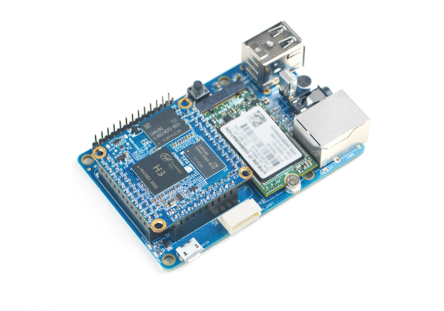
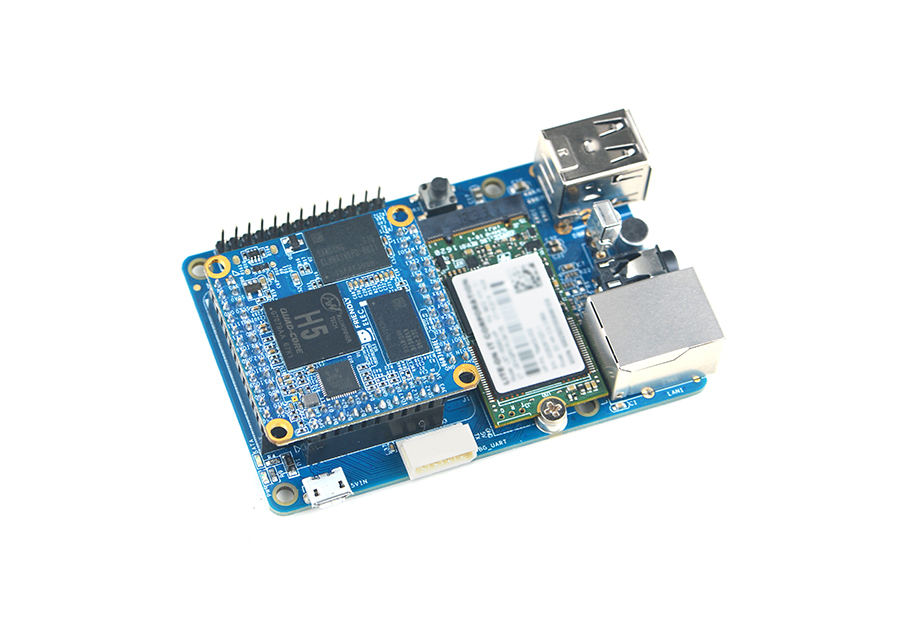
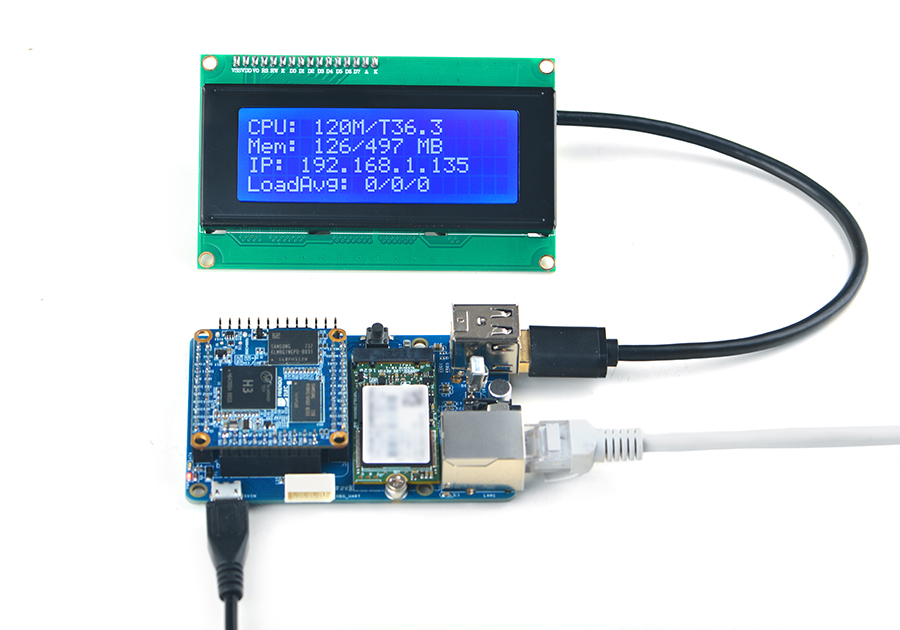
使用Mini Shield for NanoPi NEO Core/Core2底板,能方便的使用有线网络、USB等接口
Mini Shield for NanoPi NEO Core/Core2底板可装配在树莓派外壳中,参考下图装配:
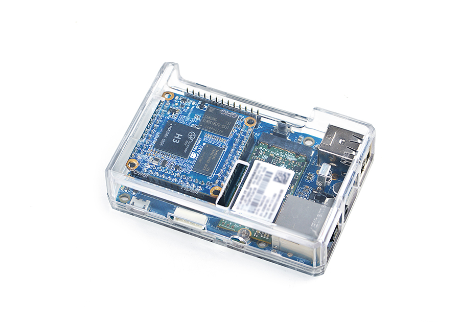
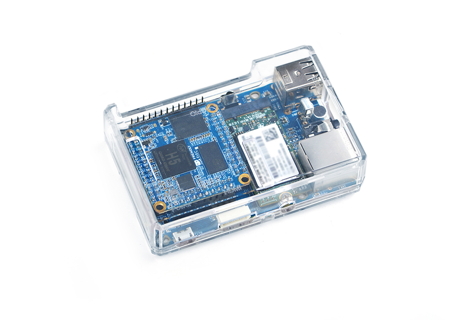
4 软件使用
4.1 1、M.2 2242接口使用
插入M.2 2242接口SSD,启动系统后,可使用如下命令查看SSD:
fdisk -l
4.2 2、从SSD运行系统
NanoPi NEO Core或Core2可以将系统运行在Mini Shield for NanoPi NEO Core/Core2的固态硬盘上,除了获得更大的存储空间外,还有如下优点:
1) 读写速度更快;
2) 使用寿命比TF卡更长;
3) 更可靠;
安装系统到固态硬盘上的方法比较简单,无需事先对SSD做准备工作,使用 npi-config 工具即可,输入以下命令启动npi-config:
sudo npi-config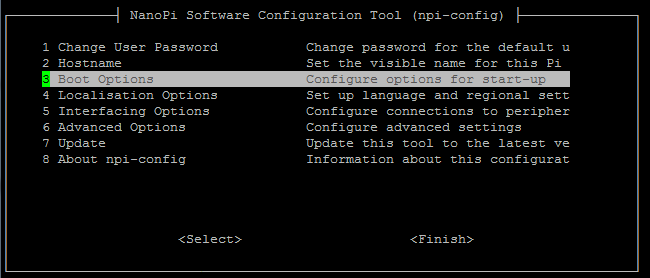
然后进入 Boot Options 菜单, 选择 Boot device,然后可以看到有两个选项可供选择:
1) D1 Hard drive
2) D2 TF card

选择 D1 Hard drive,然后按提示进行操作即可。
以后要恢复回 TF 卡启动,可在上述菜单中选择 D2 TF card。
如果你在 npi-config 中没有找到 Boot device 菜单,可能是因为你的 npi-config 版本太旧,利用菜单上的 Update 功能更新一下即可。
4.3 3、音频输入与输出
1、可使用以下命令录音:
arecord -D hw:0,0 -f cd test.wav
运行效果如下:
![]()
2、可使用以下命令播放音频文件,例如播放/root/Music/test.wav
aplay /root/Music/test.wav
运行效果如下:

可以使用alsamixer工具调节播放音乐的音量
