Mini Shield for NanoPi Duo
From FriendlyELEC WiKi
Contents
1 Introduction
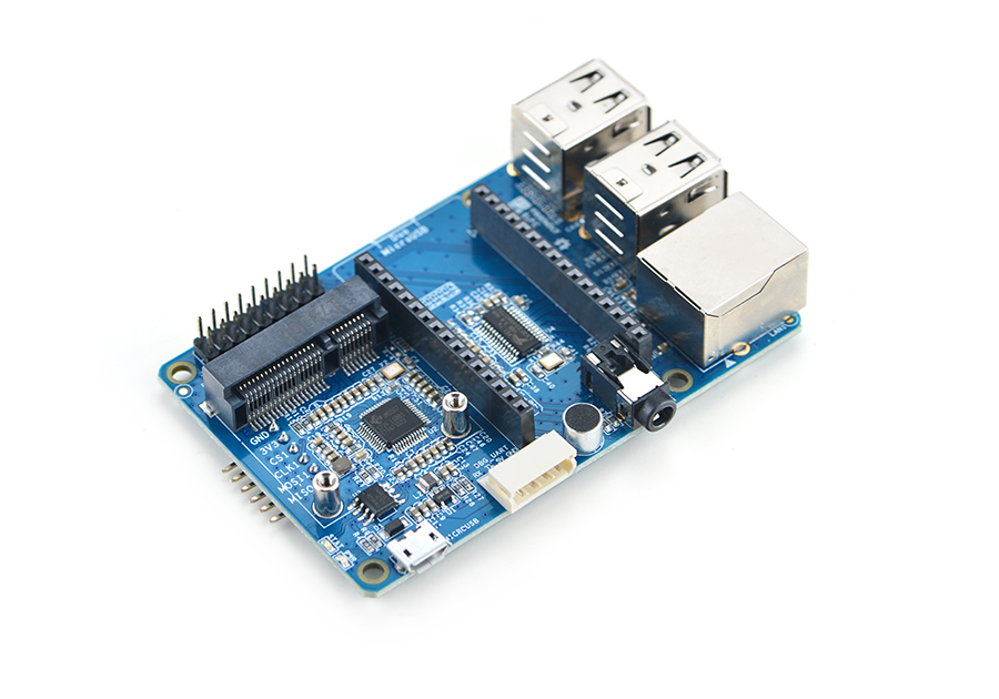
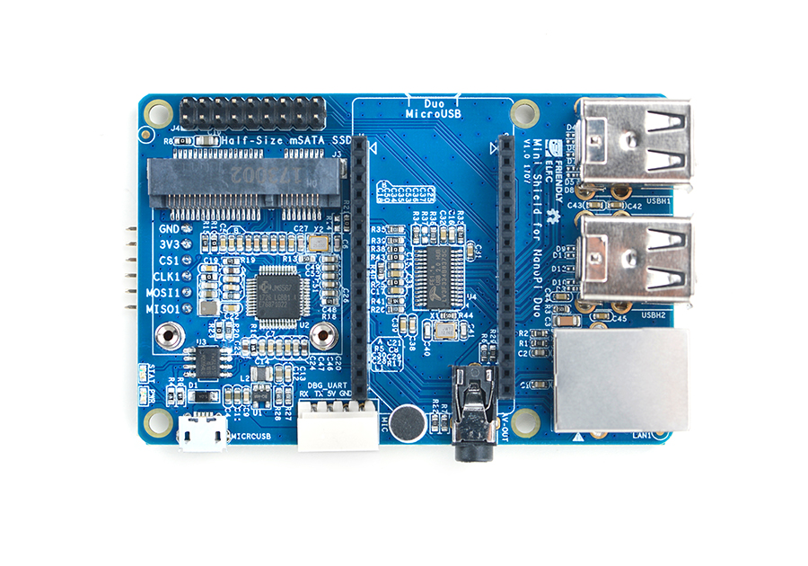
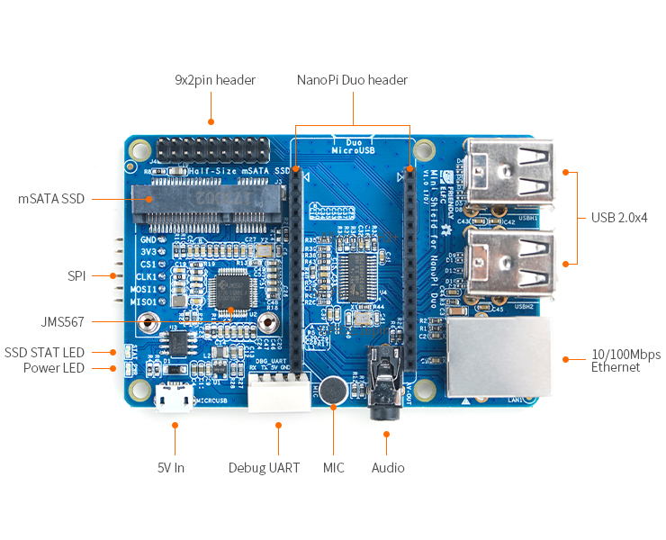
- The Mini Shield for NanoPi Duo is a dedicated carrier board for the NanoPi Duo. It extends Duo's Ethernet, serial port, audio, USB and etc.
- The mini shield has an onboard JMS567 USB to SATA IC and an mSATA interface.
- The mini shield has an onboard FE1.1s which extends four USB Host ports.
- It has a serial port and Ethernet port.
- It has an onboard microphone and a 3.5mm audio jack.
- The mini shield has a 2 x9 Pin header which extends NanoPi Duo's IO pins.
- There is a 6-pin SPI header on the reverse side.
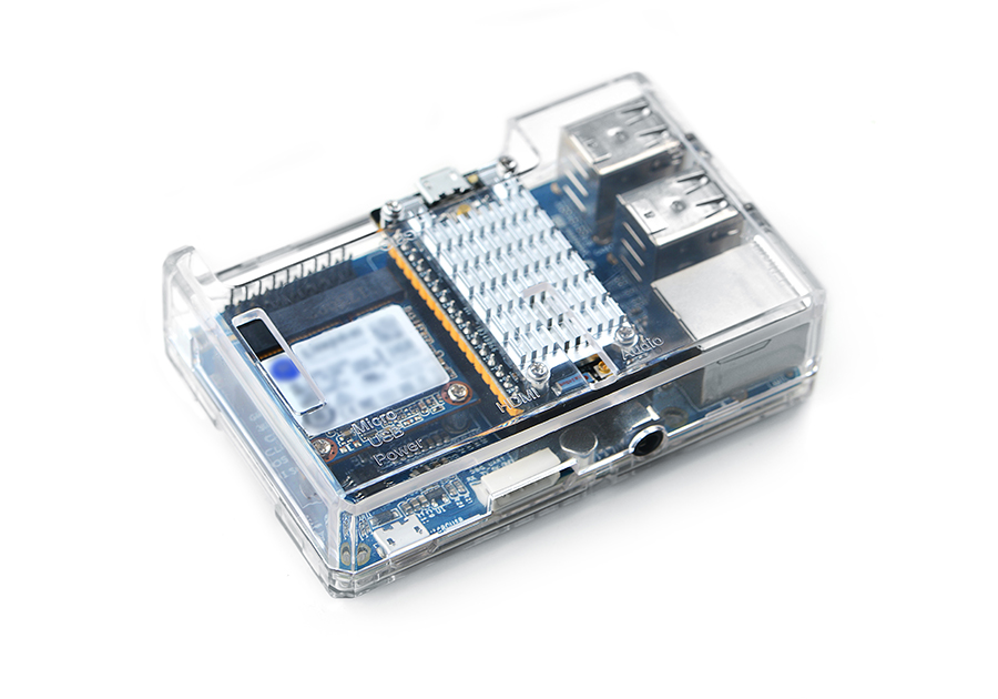
- This shield's dimension and mounting holes' positions are exactly the same as those of a Raspberry Pi therefore it can well fit into a Raspberry Pi's case.
2 Hardware Spec
- its dimension is the same as that of a Raspberry Pi and it can fit into a Pi's case
- 4 x USB Host port
- Serial port and Ethernet port
- Audio input and output
- 2 x 9 Pin GPIO header
- 6 x Pin SPI header
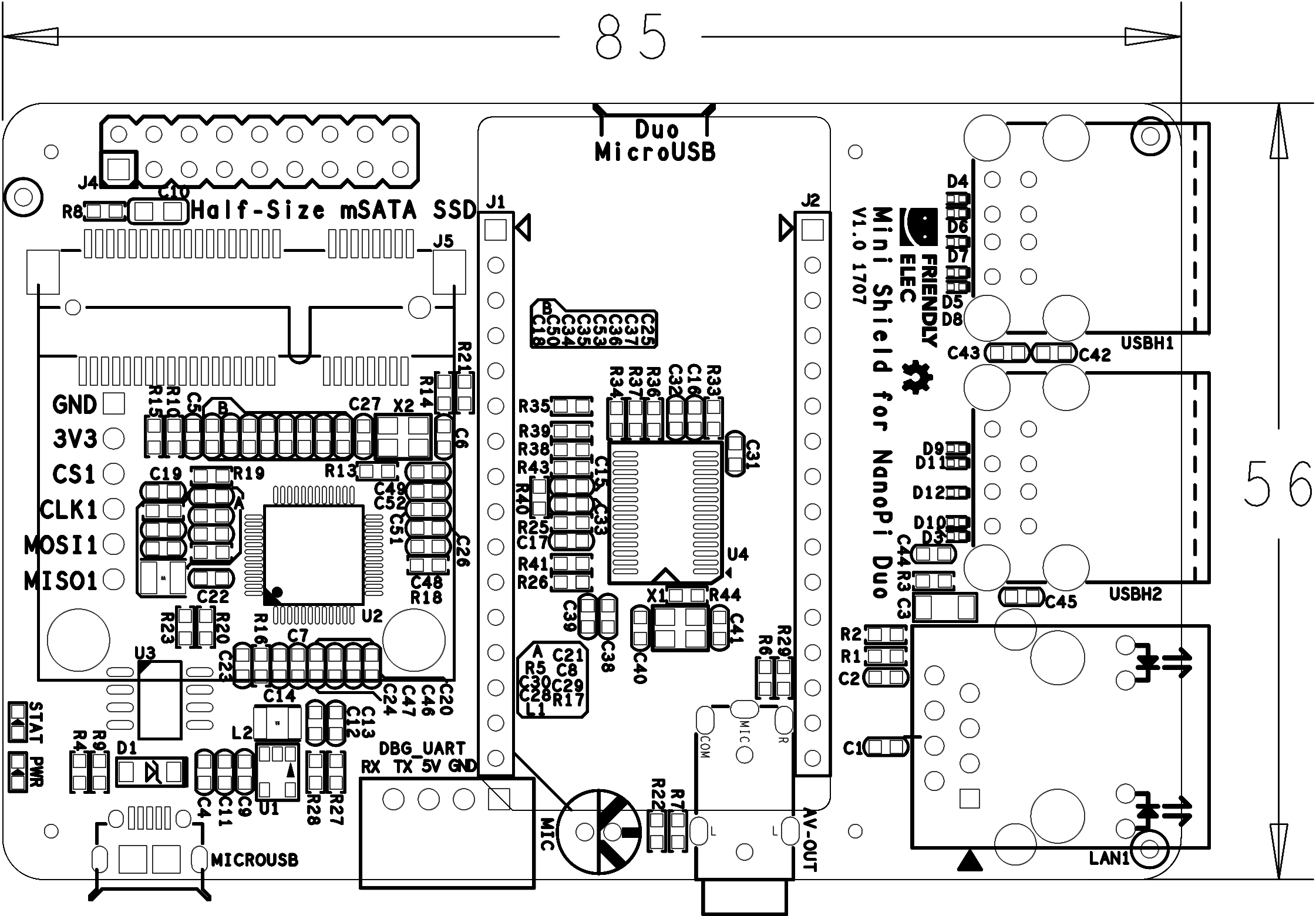
- PCB dimension(mm): 85 x 56
2.1 Diagram, Layout and Dimension
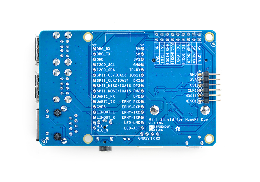
Here is a layout of ports and interfaces. There are detailed descriptions for ports and interfaces on the other side of the board.
- Mini Shield for NanoPi Duo接口引脚定义
Number# Name Number# Name 1 VDD_5V 1 DEBUG_RX(UART_RXD0)/GPIOA5/PWM0 2 VDD_5V 2 DEBUG_TX(UART_TXD0)/GPIOA4 3 SYS_3.3V 3 GND 4 GND 4 I2C0_SCL/GPIOA11 5 GPIOL11/IR-RX 5 I2C0_SDA/GPIOA12 6 GPIOG11 6 UART3_TX/SPI1_CS/GPIOA13 7 USB-DM3 7 UART3_RX/SPI1_CLK/GPIOA14 8 USB-DP3 8 UART3_CTS/SPI1_MISO/GPIOA16 9 USB-DM2 9 UART3_RTS/SPI1_MOSI/GPIOA15 10 USB-DP2 10 UART1_RX/GPIOG7 11 EPHY-RXN 11 UART1_TX/GPIOG6 12 EPHY-RXP 12 CVBS 13 EPHY-TXN 13 LINEOUT_L 14 EPHY-TXP 14 LINEOUT_R 15 EPHY-LED-LINK 15 MIC_P 16 EPHY-LED-SPD 16 MIC_N
- 2x9 Pin排针引脚定义
Number# Name Number# Name 1 SYS_3.3V 2 VDD_5V 3 I2C0_SDA / GPIOA12 4 VDD_5V 5 I2C0_SCL / GPIOA11 6 GND 7 GPIOG11 8 UART1_TX / GPIOG6 9 GND 10 UART1_RX / GPIOG7 11 SPI1_MOSI/GPIOA15 12 GPIOL11 13 SPI1_MISO/GPIOA16 14 GND 15 SPI1_CLK/GPIOA14 16 SPI1_CS/GPIOA13 17 SYS_3.3V 18 NC
- 6 Pin SPI排针引脚定义
Number# Name 1 GND 2 SYS_3.3V 3 SPI1_CS/GPIOA13 4 SPI1_CLK/GPIOA14 5 SPI1_MOSI/GPIOA15 6 SPI1_MISO/GPIOA16
3 硬件连接
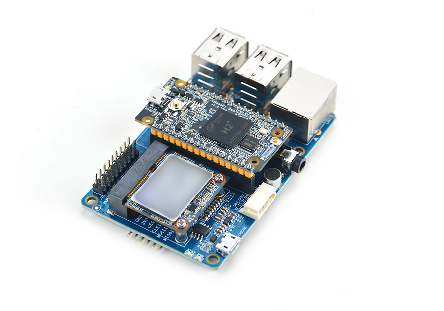
NanoPi Duo可直接装配在Mini Shield for NanoPi Duo底板上,装配时注意NanoPi Duo的方向,参考下图连接模块:
4 软件使用
4.1 1、mSATA接口使用
插入半高的mSATA接口SSD,启动系统后,可使用如下命令查看SSD:
fdisk -l
4.2 2、音频输入与输出
1、可使用以下命令录音:
xxxxx
xxxxx
5 相关资料
- [Schematic](Schematic - Mini Shield for NanoPi Duo.pdf)
- [Dimension](Dimension - Mini Shield for NanoPi Duo_PCB(dxf))
