Matrix - RGB LED
Contents
1 Introduction
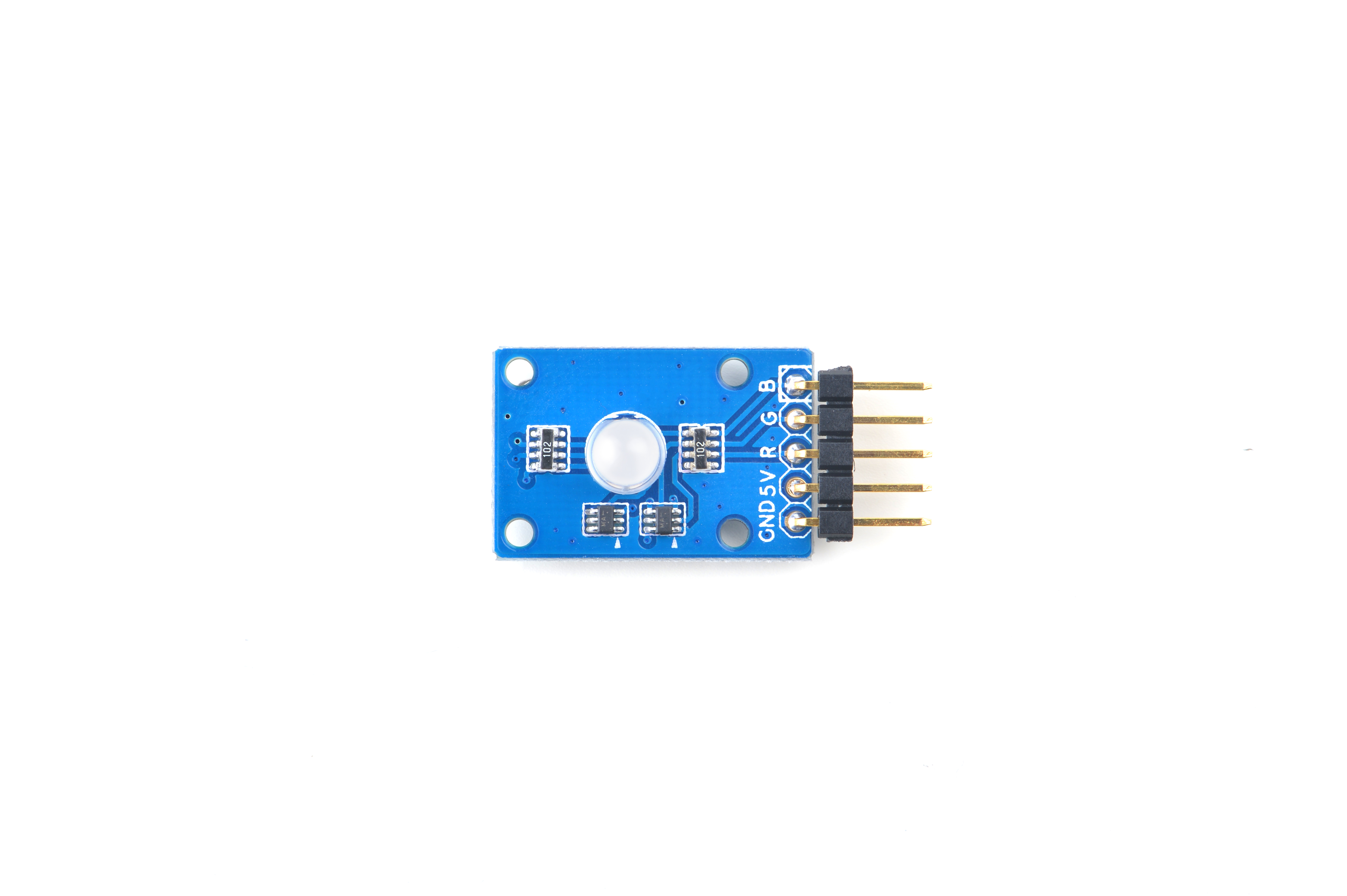
- The Matrix-RGB_LED is a RGB LED module. It has a 2.54mm pitch pin-header in which 5V is power supply, GND is ground, and R,G,B are connected to the LED’s red, green and blue pins.
- The inputs to Pin R, G and B can be either GPIO signals or PWM signals. The signal level can be either 3.3V or 5V. When the inputs to Pin R,G and B are high the LED will be the brightest.When the inputs to Pin R,G and B are low the LED will be completely off. When the inputs are PWM signals the LED's brightness can be controlled by controlling the PWM's duty cycle.
2 Features
- GPIO or PWM input, 3.3/5V, LED lightness controllable via PWM
- Small
- 2.54 mm pitch pin-header
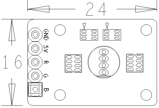
- PCB dimension(mm): 16 x 24
- Pin Description:
| Pin | Description |
| GND | Ground |
| 5V | Supply Voltage 5V |
| R | Red |
| G | Green |
| B | Blue |
3 工作原理
- RGB_LED的内部封装了三颗不同颜色的灯珠,三个灯珠的阳极或者阴极并联,当给另外三个引脚施加控制信号时,对应的LED就会亮起。当两种或三种LED亮起时,根据三原色原理,会组成其他颜色的光。You can produce different colors by adjusting PWM signals' duty cycle.
4 Applications
4.1 Connect to NanoPi M1
Refer to the following connection diagram to connect the module to the NanoPi M1:
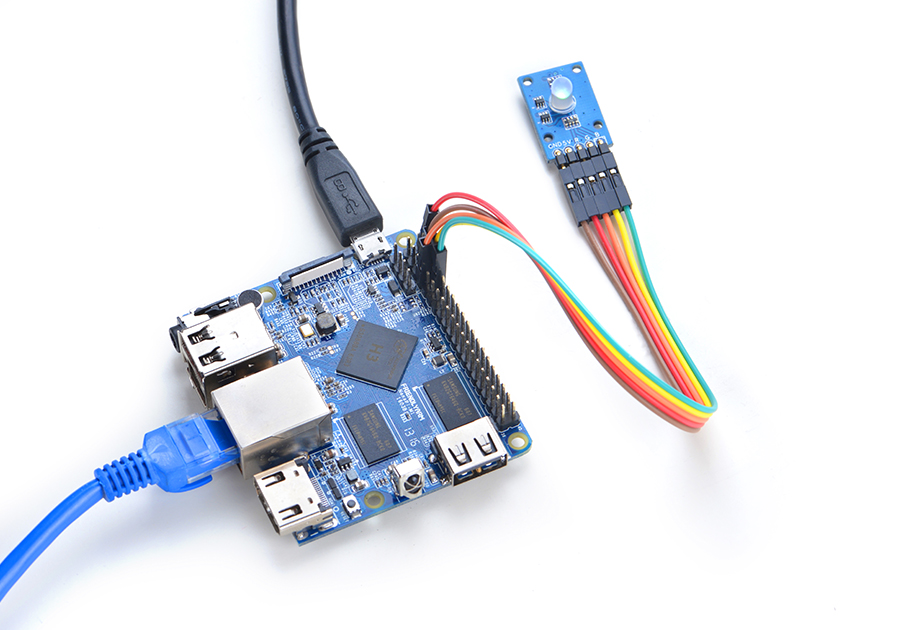
Connection Details:
| Matrix-RGBLED | NanoPi M1 |
| R | Pin7 |
| G | Pin8 |
| B | Pin10 |
| V | Pin4 |
| G | Pin6 |
4.2 Connect to NanoPi 2
Refer to the following connection diagram to connect the module to the NanoPi 2:
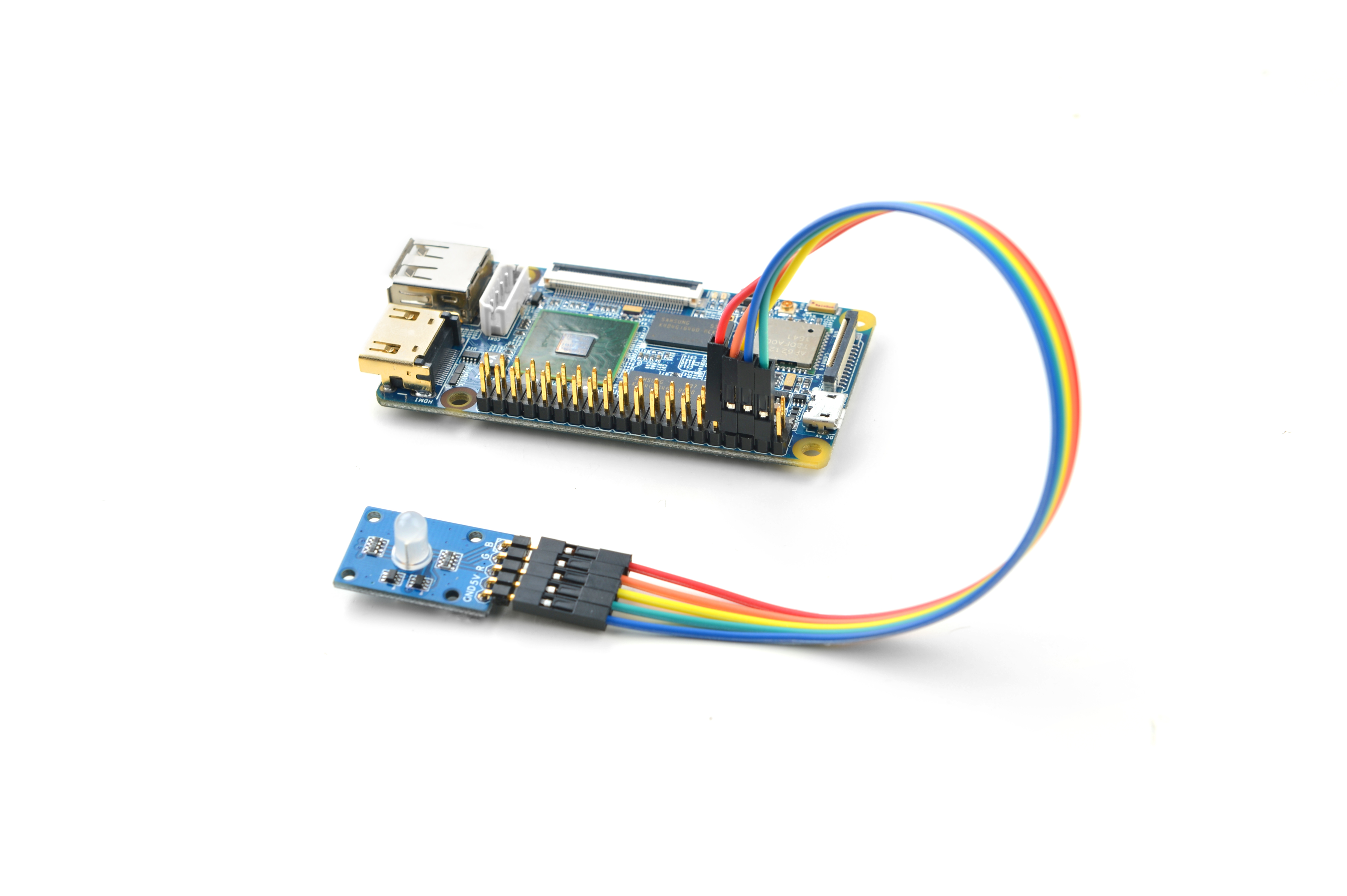
Connection Details:
| Matrix-RGBLED | NanoPi 2 |
| R | Pin7 |
| G | Pin8 |
| B | Pin10 |
| V | Pin4 |
| G | Pin6 |
4.3 Connect to NanoPi M2 / NanoPi 2 Fire
Refer to the following connection diagram to connect the module to the NanoPi M2/ NanoPi 2 Fire.
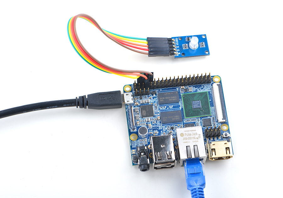
Connection Details:
| Matrix-RGBLED | NanoPi M2 |
| R | Pin7 |
| G | Pin8 |
| B | Pin10 |
| V | Pin4 |
| G | Pin6 |
4.4 Connect to NanoPC-T2
Refer to the following connection diagram to connect the module to the NanoPC-T2:
Matrix-RGBLED_NanoPC-T2
Connection Details:
| Matrix-RGBLED | NanoPC-T2 |
| R | Pin15 |
| G | Pin16 |
| B | Pin17 |
| V | Pin29 |
| G | Pin30 |
5 Compile & Run Test Program
Boot your ARM board with Debian and copy the matrix code:
$ apt-get update && apt-get install git
$ git clone https://github.com/friendlyarm/matrix.git
If your cloning is done successfully a "matrix" directory will be generated.
Compile and install Matrix:
$ cd matrix
$ make && make install
Run test program:
$ matrix-rgb_ledNote: this module is not plug and play therefore before running the module please make sure it is connected to an ARM board.
Here is what you should observe:
Set RGB LED: 0
Set RGB LED: 1
Set RGB LED: 2
Set RGB LED: 3
Set RGB LED: 4
Set RGB LED: 5
Set RGB LED: 6
Set RGB LED: 7
You will see the LED displaying different colors.
6 Code Sample
This Matrix code sample can work with all the ARM boards mentioned in this module's wiki. The name of this code sample is "matrix-rgb_led". Here is its source code:
int main(int argc, char ** argv)
{
    int ret = -1;
    int val, board;

    if ((board = boardInit()) < 0) {
        printf("Fail to init board\n");
        return -1;
    }
    if (board == BOARD_NANOPI_T2) {
        ledPin1 = GPIO_PIN(15);
        ledPin2 = GPIO_PIN(16);
        ledPin3 = GPIO_PIN(17);
    }
    if ((ret = exportGPIOPin(ledPin1)) == -1) {
        printf("exportGPIOPin(%d) failed\n", ledPin1);
    }
    if ((ret = setGPIODirection(ledPin1, GPIO_OUT)) == -1) {
        printf("setGPIODirection(%d) failed\n", ledPin1);
    }
    if ((ret = exportGPIOPin(ledPin2)) == -1) {
        printf("exportGPIOPin(%d) failed\n", ledPin2);
    }
    if ((ret = setGPIODirection(ledPin2, GPIO_OUT)) == -1) {
        printf("setGPIODirection(%d) failed\n", ledPin2);
    }
    if ((ret = exportGPIOPin(ledPin3)) == -1) {
        printf("exportGPIOPin(%d) failed\n", ledPin3);
    }
    if ((ret = setGPIODirection(ledPin3, GPIO_OUT)) == -1) {
        printf("setGPIODirection(%d) failed\n", ledPin3);
    }
    signal(SIGINT, intHandler);
    for (val = 0; val < 8; val++) {
        printf("Set RGB LED: %x\n", val);
        setRGBLED(val);
        usleep(1000 * 1000);
    }
    unexportGPIOPin(ledPin1);
    unexportGPIOPin(ledPin2);
    unexportGPIOPin(ledPin3);
    return 0;
}
For more details about this APIs called in this code sample refer to Matrix API reference manual
