NanoPi
Contents
1 Introduction
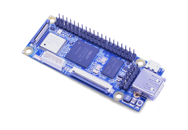
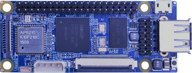
The NanoPi is a low power consumption, Samsung S3C2451 based ARM SOC that FriendlyARM developed for Linux hackers, Hobby makers and hobbyists. Its size is only half of the Raspberry Pi(RPi) and its GPIO pin is compatible with the RPi’s. The NanoPi integrates both the WiFi and Bluetooth 4.0,and has MiPi sockets for cameras and LCDs. It is easy to run and install Linux/Debian from a TF card. These features make it a good platform for applications in IOT, unmanned vehicles, drones and intelligent devices.
2 Hardware Features
- CPU: Samsung S3C2451, 400Mhz
- RAM: 64M DDR2
- Integrated SDIO WiFi and Bluetooth
- USB Type A x1
- Debugging Serial Port x1
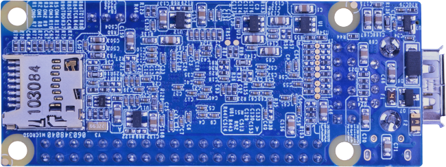
- microSD Slot x1
- microUSB x1: for power and data transmission. It can be configured as a serial port or Ethernet
- LCD Interface: 0.5mm spacing FPC socket, full color LCD (RGB:8-8-8)
- DVP Camera interface:0.5mm spacing FPC socket. It includes ITU-R BT 601/656 8-bit, I2C and IO
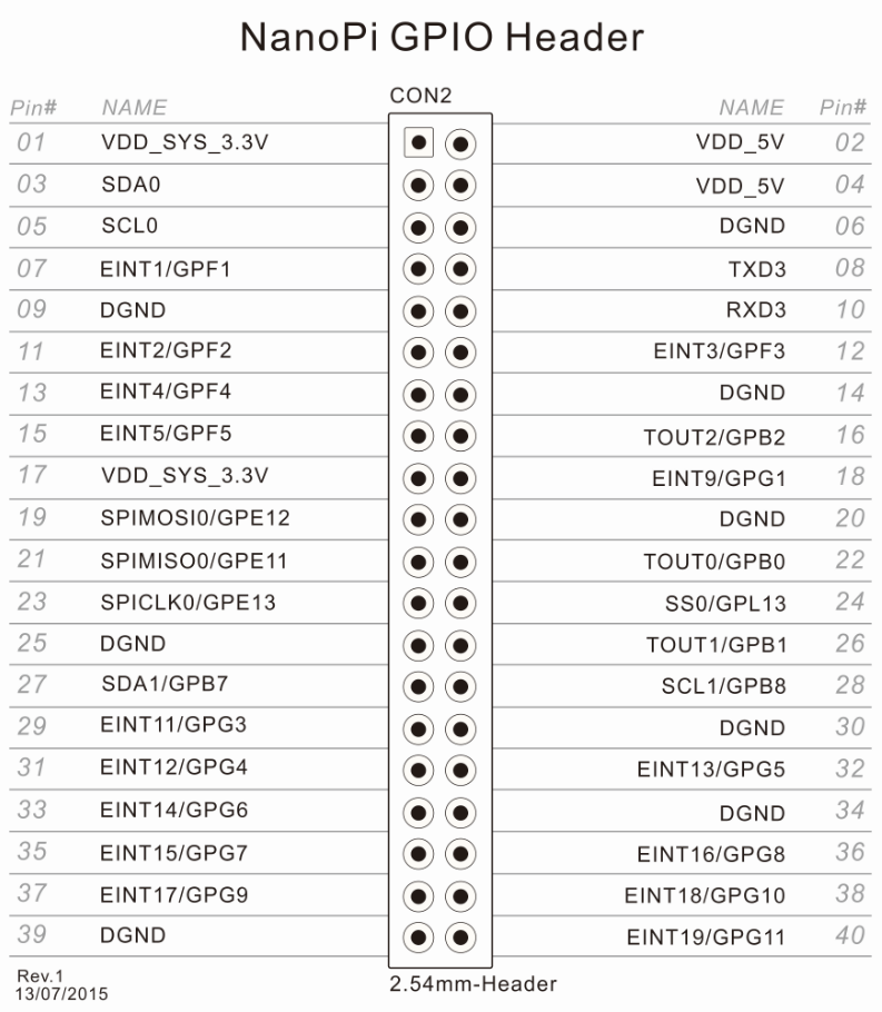
- GPIO1: 2.54mm spacing 40pin, compatible with Raspberry Pi's GPIO. It includes UART, SPI, I2C, IO etc
- GPIO2: 2.54mm spacing 12pin. It includes I2S, I2C, UART etc.
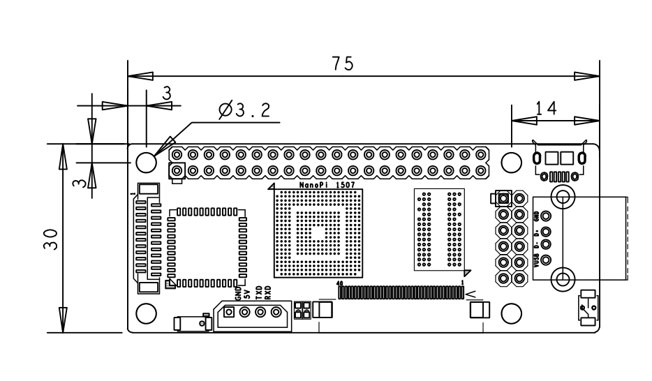
- PCB dimension: 75 x 30 mm
- Power: DC 5V
- Bootloader and OS: u-boot, Linux-4.1 and Debian
3 Diagram, Layout and Dimension
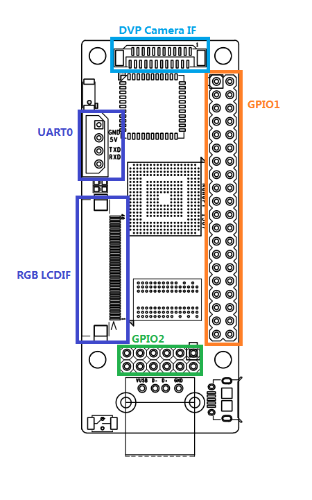
3.1 Layout
- GPIO1 Pin Spec
- GPIO2 Pin Spec
Pin# Name Pin# Name 1 VDD_5V 2 VDD_SYS_3.3V 3 TXD2 4 RXD2 5 SDA0 6 SCL0 7 IISSDO0 8 IISSDI0 9 IISSCLK0 10 IISLRCK0 11 IISCDCLK0 12 DGND
- Debug Port CON1(UART0)
Pin# Name 1 DGND 2 VDD_5V 3 TXD0 4 RXD0
- DVP Camera IF Pin Spec
Pin# Name 1, 2 VDD_SYS_3.3V 7,9,13,15,24 DGND 3 SCL0 4 SDA0 5 GPH13 6 GPJ12 8 XCLK 10 NC 11 VSYNC 12 HREF 14 PCLK 16-23 Data bit7-0
- RGB LCD IF Pin Spec
Pin# Name 1, 2 VDD_5V 11,20,29 DGND 3-10 Blue LSB to MSB 12-19 Green LSB to MSB 21-28 Red LSB to MSB 30 GPG12 31 GPG2 32 XnRSTOUT Form CPU 33 VDEN 34 VSYNC 35 HSYNC 36 LCDCLK 37,38,39,40 XM,XP,YM,YP
- Note:
- VDD_SYS_3.3V: 3.3V power output
- VDD_5V: 5V power input/output. When the external device’s power is greater than the MicroUSB’s the external device is charging the board otherwise the board powers the external device. The input range is 4.7V ~ 5.6V
- 3. For more details please refer to the document:NanoPi-1507-Schematic.pdf
3.2 Board Dimension
- 3. For more details please refer to the document:NanoPi-1507-Dimesions(dxf).zip
4 Get Started
4.1 Stuff You Need
Before play with your NanoPi please get the following items ready
- NanoPi
- microSD card/TF card: > 64M
- microUSB cable
- a Host running Ubuntu and connected to the internet
4.2 Make an Installation MicroSD Card
- 1) Insert your microSD card to your host running Ubuntu and check your SD card's device name
dmesg | tail
Search the messages output by "dmesg" for similar words like "sdc: sdc1 sdc2". If you can find them it means your SD card is recognized as "/dev/sdc". Or you can check that by commanding "cat /proc/partitions".
- 2) Flash Firmware to MicroSD Card
git clone https://github.com/friendlyarm/sd-fuse_nanopi.git
cd sd-fuse_nanopi
su
./fusing.sh /dev/sdx
(Note: you need to replace "/dev/sdx" with the device name in your system)
4.3 Run System
Insert this MicroSD card to your NanoPi, connect it to a PC via a MicroUSB cable the NanoPi will be automatically powered on. If you can see the blue LED flashing it means your board is running now
4.4 Log on NanoPi via MicroUSB
After connecting your NanoPi to you PC host (running Ubuntu) please type "dmesg" in your PC's command line. If you can find the following messages it means your NanoPi is correctly connected to your host and runs well:
[12601.100339] usb 2-1.7: Product: FriendlyARM Gadget v2.4
[12601.100343] usb 2-1.7: Manufacturer: Linux 4.1.2-FriendlyARM with s3c-hsudc
[12601.103192] cdc_acm 2-1.7:2.0: This device cannot do calls on its own. It is not a modem.
[12601.103368] cdc_acm 2-1.7:2.0: ttyACM0: USB ACM device
[12601.105300] cdc_ether 2-1.7:2.2 usb0: register 'cdc_ether' at usb-0000:00:1d.0-1.7, CDC Ethernet Device, 46:a1:e7:6d:5c:32
If you command "ifconfig" and find a "usb0" device you can SSH to 192.168.100.1 to log on your NanoPi:
ssh root@192.168.100.1
After it prompts you to input your password you can try "fa"
4.5 Setup Wi-Fi
SSH to your NanoPi and run the following commands to setup your WiFi:
wpa_passphrase YourWiFiESSID 'YourWiFiPassword' >> /etc/wpa.conf
wpa_cli -iwlan0 reconfigure
Please replace "YourWiFiESSID" and "YourWiFiPassword" with your WiFiESSID and password. After you power on your board it will automatically connect to your WiFi source. You can configure your AP settings by editing "/etc/wpa.conf". By default your IP is DHCP. If you want to configure it as a static IP you can edit "/usr/sbin/wpa_action" by replacing "udhcpc" with "ifconfig".
4.5.1 扫描无线AP
用以下命令搜索周边的无线AP:
wpa_cli -iwlan0 scan
wpa_cli -iwlan0 scan_result
5 如何编译系统
5.1 安装交叉编译器
首先下载并解压编译器:
git clone https://github.com/friendlyarm/prebuilts.git
tar xvzf prebuilts/gcc/arm-linux-gcc-4.4.3.tar.gz -C /
然后将编译器的路径加入到PATH中,用vi编辑vi ~/.bashrc,在末尾加入以下内容:
export PATH=/opt/FriendlyARM/toolschain/4.4.3/bin/:$PATH
执行一下~/.bashrc脚本让设置立即在当前shell窗口中生效,注意"."后面有个空格:
. ~/.bashrc5.2 编译U-Boot
下载U-Boot源代码并编译,注意分支是nanopi:
git clone https://github.com/friendlyarm/uboot_nanopi.git
cd uboot_nanopi
git checkout nanopi
make nanopi_config
make
编译成功结束后您将获得u-boot.bin, 如果想马上就测试u-boot,可使用脚本fusing.sh烧写新的u-boot 到SD 卡。
假设您的 SD 卡对应设备名是/dev/sdd,以root运行以下命令:
su
./fusing.sh /dev/sdd
注意:以上操作会破坏SD卡的数据,请先进行备份。
5.3 编译Linux kernel
5.3.1 编译内核
下载内核源代码并编译
git clone https://github.com/friendlyarm/linux-4.x.y.git
cd linux-4.x.y
git checkout nanopi-v4.1.y
make nanopi_defconfig
touch .scmversion
make
NanoPi内核所属的分支是nanopi-v4.1.y,在开始编译前先切换分支,编译成功结束后,新生成内核烧写文件为 arch/arm/boot/zImage 。
5.3.2 编译内核模块
目前的内核配置会编译生成内核模块,如ipv6、netfilter,通常在编译内核时,内核模块(.ko)已经编译,如果您有新的内核模块或者内核配置有变化,则需要编译安装内核模块并打包成 kernel-modules.tgz,然后替换Rootfs下的 basefs/kernel-modules.tgz。
以root用户运行以下命令安装.ko到/tmp/nanopi-modules 。
make INSTALL_MOD_PATH=/tmp/nanopi-modules modules_install
接下来可对内核模块进行strip,然后创建压缩包。
cd /tmp/nanopi-modules/lib/
find . -name \*.ko | xargs arm-linux-strip --strip-unneeded
tar czvf kernel-modules.tgz modules/
如果想测试新编译的内核模块,也可以解压压缩包或复制modules 到已制作好的能启动NanoPi的SD卡的rootfs下的/lib 目录。 假设SD卡的rootfs已经mount到 /media/fa/NANOPI,以root 运行以下命令:
rm -rf /media/fa/NANOPI/lib/modules/
tar xzvf kernel-modules.tgz -C /media/fa/NANOPI/lib/
5.4 编译制作文件系统
下面的命令将下载文件系统源码包并编译,注意需要在root用户下编译,可用su命令切换:
git clone https://github.com/friendlyarm/rootfs_nanopi.git
cd rootfs_nanopi
git checkout nanopi
su
make && make install && make strip
编译成功结束后,将看到以下信息:
RootFS (core) successfully installed to:
   /tmp/FriendlyARM/nanopi/rootfs

Copyright 2015 FriendlyARM (http://www.arm9.net/)
上面的信息提示我们编译生成的文件系统存放的位置为/tmp/FriendlyARM/nanopi/rootfs,我们把它压缩成一个压缩包:
cd /tmp/FriendlyARM/nanopi
tar czvf rootfs.tgz rootfs/
5.5 使用自已编译的文件生成制作SD卡
5.5.1 重新制作SD卡系统
先下载SD卡烧写的工具包,并切换到相应master分支:
git clone https://github.com/friendlyarm/sd-fuse_nanopi.git
cd sd-fuse_nanopi
git checkout master
在sd-fuse_nanopi下有个prebuilt,用于存放SD系统运行所需的二进制文件:
Bootloader: u-boot.bin
内核命令行参数: sdenv.raw
Linux内核:zImage
文件系统压缩包: rootfs.tgz
你只需要将上面章节中编译生成的文件替换它们,就可以测试运行你所编译的系统了,替换文件后,在sd-fuse_nanopi目录下执行以下命令制作SD卡:
su
./fusing.sh /dev/sdx
(注:/dev/sdx请替换为实际的SD卡设备文件名)
烧写成功完成后,把SD卡放入NanoPi运行试试吧。
5.5.2 更新U-Boot环境变量
制作好的SD启动NanoPi 后,如果通过串口在U-Boot命令模式下修改了环境变量,如bootargs,现在想要把这个修改后的环境用于制作其它新的SD卡,则需要把保存在卡的U-Boot环境变量数据读出来,替换掉prebuilt 下的 sdenv.raw,然后烧写新的SD卡即可。
./readenv.sh /dev/sdd
cp sdenv.raw prebuilt/
5.5.3 关于SD卡RAW文件
由于CPU S3C2451的iROM 是从SD卡的尾部来读取Bootloader,且普通SD卡和SDHC卡的位置不同,而不同品牌或是不同容量的SD卡的大小又是不同的,因此没办法创建适应不同卡的RAW文件。
如果您有一批大小完全一致的SD卡,可使用工具如linux下的dd 读取已经制作好的SD 卡的全部数据,保存为RAW文件,然后将此文件写入其它大小相同的SD卡。
另外,由于现在的SD卡容量通常都比较大,对于8 GB的SD卡,写一个RAW文件将需要较长时间,而目前的rootfs实际只有 ~23 MB,因此直接使用脚本制作SD卡将更快。
6 扩展连接
6.1 连接使用摄像头模块
6.2 连接使用TFT LCD
6.3 连接使用Matrix入门DIY套件
7 玩转NanoPi
7.1 制作一台4.3英寸小电脑
7.2 制作无线智能小车
8 资源链接
- [Schematic]( NanoPi-1507-Schematic.pdf)
- [Dimensions]( NanoPi-1507-Dimesions(dxf).zip )
- [S3C2451芯片手册](S3C2451_UM_REV1.1.pdf)
- [RT8059芯片手册]( RT8059.pdf)
- [XC6209芯片手册]( XC6209.pdf)
- [DDR2 RAM芯片手册]( K4T51163QI_rev1.1.pdf)
- [AP6210规格书]( AP6210_V1.2_12262012.pdf)
