Matrix - 2'8 SPI Key TFT
Contents
1 Introduction
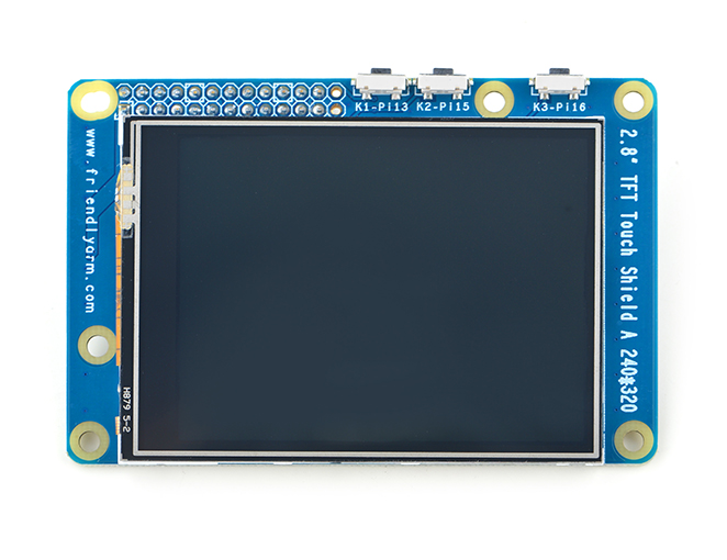
- The Matrix-2.8_SPI_Key_TFT LCD is a FriendlyARM developed LCD module with resistive touch panel. Its resolution is 320 x 240. It uses the ST7789S IC and XPT2046 resistive touch IC. It has SPI interface and three configurable user keys.
- Specification
| LCD Dimension | 2.8" |
| Display Area | 57.6mm*43.2mm |
| Driver IC | ST7789S |
| Resolution | 320 * 240(RGB) |
| MCU Interface | SPI |
| Power Supply | 5V |
| Backlight Voltage | 5V |
| Touch | Resistive Touch, tempered glass touch panel |
By default the module's backlight is turned on after the module is powered on. LED_EN can be set to turn off the backlight. If you don’t want the backlight to be turned on after the module is powered on you can take off R12 and in this case you can turn on the backlight by pulling up LED_EN.
2 Features
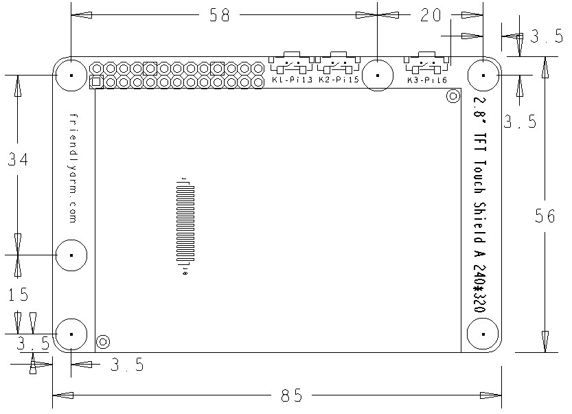
- PCB dimension(mm):
- Pin Description:
| Pin | Description | Pin | Description |
| 1 | VDD_3.3V | 2 | VDD_5V |
| 3 | NC | 4 | VDD_5V |
| 5 | NC | 6 | GND |
| 7 | LCD_RESET | 8 | NC |
| 9 | GND | 10 | NC |
| 11 | LED_EN | 12 | NC |
| 13 | KEY_1 | 14 | GND |
| 15 | KEY_2 | 16 | KEY_3 |
| 17 | VDD_3.3V | 18 | T_IRQ |
| 19 | SPI_MOSI | 20 | GND |
| 21 | SPI_MISO | 22 | LCD_D/C |
| 23 | SPI_CLK | 24 | LCD_CS |
| 25 | GND | 26 | T_CS |
3 Applications
3.1 Connect to NanoPi M1
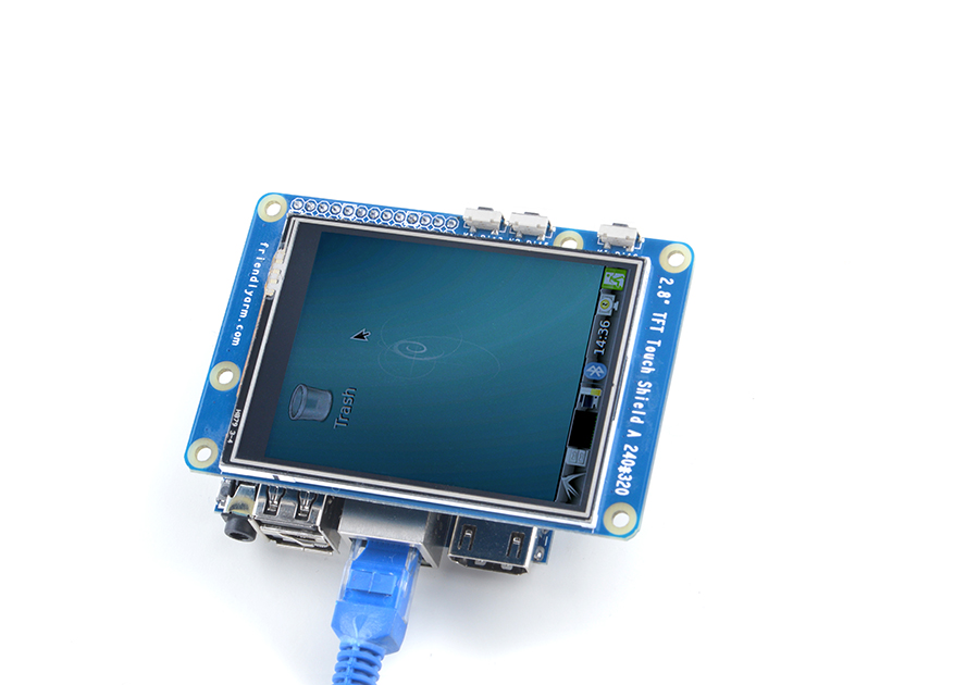
Please refer to the following connection diagram to connect the module to the NanoPi M1:
3.2 Connect to NanoPi 2
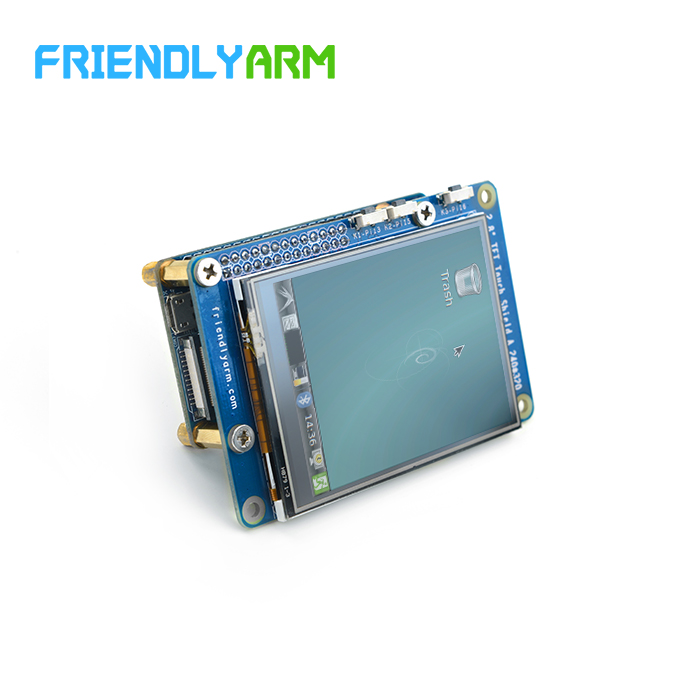
Please refer to the following connection diagram to connect the module to the NanoPi 2:
3.3 Connect to NanoPi M2 / NanoPi 2 Fire
Please refer to the following connection diagram to connect the module to the NanoPi M2 / NanoPi 2 Fire:
Matrix-2'8_SPI_Key_TFT_nanopi_m2
4 Compile & Run Test Program
Boot your ARM board with Debian and copy the matrix code:
$ apt-get update && apt-get install git
$ git clone https://github.com/friendlyarm/matrix.git
If your cloning is done successfully a "matrix" directory will be generated.
Compile and install Matrix:
cd matrix/demo/nanopi-status
./build.sh
./run.sh /dev/fb-st7789s
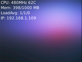
The nanopi-status is a small Qt utility which can be used to list system's basic information. Here is what you should expect to observe:
5 Display Debian GUI on 2.8"LCD
Boot your ARM board with Debian and and launch the Debian GUI by running the following commands:
$ cd matrix/demo/nanopi-status/
$ ./display-debian.sh /dev/fb-st7789s
Calibrate the screen by following the four points' movement:
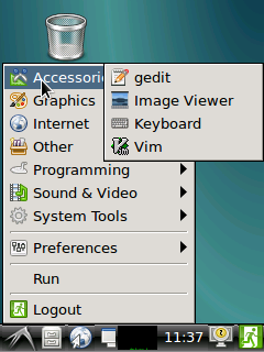
After calibration is done you will see the following system information:
Section "InputClass"
        Identifier      "calibration"
        MatchProduct    "ADS7846 Touchscreen"
        Option  "Calibration"   "196 3825 3887 358"
        Option  "SwapAxes"      "0"
EndSection
Copy and paste the information to the "/usr/share/X11/xorg.conf.d/99-calibration.conf" file, save it and this will be used as your calibration data when you reboot your board.
6 Resources
7 Update Log
7.1 Feb-24-2016
- Added the driver's source code location in Section 5.2
7.2 June-17-2016
- Re-organized and simplified wiki
