WiringNP: NanoPi NEO/NEO2/Air GPIO Programming with C
Contents
[hide]1 Introduction to WiringPi
The wiringPi library was initially developed by Gordon Henderson in C. It contains libraries to access GPIO, I2C, SPI, UART, PWM and etc.
The wiringPi library contains various libraries, header files and a commandline utility:gpio. The gpio utility can be used to read and write GPIO pins.
2 Introduction to WiringNP
The wiringPi library was initially developed for BCM2835, and later migrated to Allwinner H3 and renamed as WiringNP. Now the WiringNP works with FriendlyElec's NanoPi M1, NanoPi NEO and NanoPi NEO2. The first version was made by wertyzp. FriendlyElec developed a version for Allwinner H5 based NanoPi NEO2.
Here is WiringNP's project page: https://github.com/friendlyarm/WiringNP
3 Install WiringNP on NEO/NEO2
Log into your nano board via SSH, open a terminal and install the WiringNP library by running the following commands:
git clone https://github.com/friendlyarm/WiringNP
cd WiringNP/
chmod 755 build
./build
4 Install WiringNP on NanoPi M1
Log into your nano board via SSH, open a terminal and install the WiringNP library by running the following commands:
git clone https://github.com/friendlyarm/WiringNP
cd WiringNP/
git checkout nanopi-m1
chmod 755 build
./build
4.1 Verify WiringNP
The WiringNP library contains a set of gpio commands. Users can use them to access the GPIO pins on a nano board. You can verify your WiringNP by running the following command:
gpio readall
If your installation is successful the following messages will show up. Here is the message list for NEO2:
root@FriendlyARM:~# gpio readall
  +-----+-----+----------+------+---+-NanoPi NEO/NEO2--+------+----------+-----+-----+
 | BCM | wPi |   Name   | Mode | V | Physical | V | Mode | Name     | wPi | BCM |
 +-----+-----+----------+------+---+----++----+---+------+----------+-----+-----+
 |     |     |     3.3V |      |   |  1 || 2  |   |      | 5V       |     |     |
 |  12 |   8 |  GPIOA12 |  OFF | 0 |  3 || 4  |   |      | 5V       |     |     |
 |  11 |   9 |  GPIOA11 |  OFF | 0 |  5 || 6  |   |      | 0v       |     |     |
 | 203 |   7 |  GPIOG11 |  OUT | 1 |  7 || 8  | 0 | OFF  | GPIOG6   | 15  | 198 |
 |     |     |       0v |      |   |  9 || 10 | 0 | OFF  | GPIOG7   | 16  | 199 |
 |   0 |   0 |   GPIOA0 |  OFF | 0 | 11 || 12 | 0 | OFF  | GPIOA6   | 1   | 6   |
 |   2 |   2 |   GPIOA2 |  OFF | 0 | 13 || 14 |   |      | 0v       |     |     |
 |   3 |   3 |   GPIOA3 |  OFF | 0 | 15 || 16 | 0 | OFF  | GPIOG8   | 4   | 200 |
 |     |     |     3.3v |      |   | 17 || 18 | 0 | OFF  | GPIOG9   | 5   | 201 |
 |  64 |  12 |   GPIOC0 |  OFF | 0 | 19 || 20 |   |      | 0v       |     |     |
 |  65 |  13 |   GPIOC1 |  OFF | 0 | 21 || 22 | 0 | OFF  | GPIOA1   | 6   | 1   |
 |  66 |  14 |   GPIOC2 |  OFF | 0 | 23 || 24 | 0 | OFF  | GPIOC3   | 10  | 67  |
 +-----+-----+----------+------+---+----++----+---+------+----------+-----+-----+
 | BCM | wPi |   Name   | Mode | V | Physical | V | Mode | Name     | wPi | BCM |
 +-----+-----+----------+------+---+-NanoPi NEO/NEO2--+------+----------+-----+-----+

 +-----+----NanoPi NEO/NEO2 Debug UART-+----+
 | BCM | wPi |   Name   | Mode | V | Ph |
 +-----+-----+----------+------+---+----+
 |   4 |  17 |   GPIOA4 | ALT5 | 0 | 37 |
 |   5 |  18 |   GPIOA5 | ALT4 | 0 | 38 |
 +-----+-----+----------+------+---+----+
5 Code Sample with WiringNP
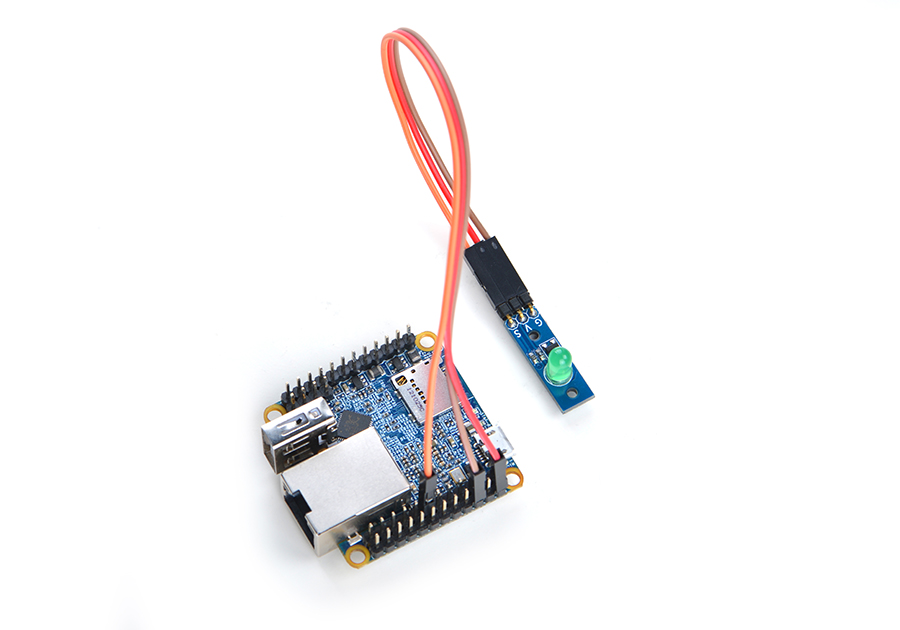
Here is a setup to connect a Matrix - LED module to a NanoPi NEO2:

Here is the connection:
| Matrix-LED | NanoPi M1 |
| S | Pin7 |
| V | Pin4 |
| G | Pin6 |
We will show how to use WiringNP to control a LED module.
In the following code samples index 7 stands for Pin7. We will use "7" to access this physical pin.
5.1 C Source Code
Make a C source file:
vi test.cType the following lines:
#include <wiringPi.h>
int main(void)
{
  wiringPiSetup() ;
  pinMode (7, OUTPUT) ;
  for(;;)
  {
    digitalWrite(7, HIGH) ;
    delay (500) ;
    digitalWrite(7,  LOW) ;
    delay (500) ;
  }
}
Compile and run "test.c":
gcc -Wall -o test test.c -lwiringPi -lpthread
sudo ./test
You can see the LED is blinking.
5.2 PWM Code Sample
The PWM pin in NanoPi NEO/NEO2 is multiplexing which can be set to either PWM or SerialPort0. To set this pin to PWM you need to run "sudo npi-config" and enter the "Advanced Options" menu to Enable/Disable PWM. Note: after PWM is enabled SerialPort0 will not be accessed and you need to login your board via SSH.
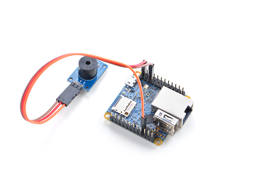
Here is a hardware setup to connect a Matrix - Buzzer to a NanoPi NEO2:

Create a source file in C:
vi pwmtest.cType the following code:
#include <wiringPi.h>
#include <stdio.h>
#include <stdlib.h>
#include <stdint.h>
int main (void)
{
  int l ;
  printf ("PWM test program\n") ;

  //using wiringPi Pin Number
  int pin = 18;
  if (wiringPiSetup () == -1)
    exit (1) ;

  /*
  //using Physical Pin Number
  int pin = 38;
  if (wiringPiSetupPhys() == -1)
    exit (1) ;
  */

  /*
  //using BCM Pin Number
  int pin = 5;
  if (wiringPiSetupGpio() == -1)
    exit (1);
  */

  pinMode (pin, PWM_OUTPUT);
  for (;;) {
    for (l = 0 ; l < 1024 ; ++l) {
      pwmWrite (pin, l) ;
      delay (1) ;
    }
    for (l = 1023 ; l >= 0 ; --l) {
      pwmWrite (pin, l) ;
      delay (1) ;
    }
  }
  return 0 ;
}
Compile the pwmtest.c file and run the generated executable:
gcc -Wall -o pwmtest pwmtest.c -lwiringPi -lpthread
./pwmtest
Connect a PWM beeper to a NEO/NEO2 and the beeper will sound.
5.3 Shell Script
Make a shell script:
vi test.shType the following lines:
LED=7
gpio mode $LED out
while true; do
  gpio write $LED 1
  sleep 0.5
  gpio write $LED 0
  sleep 0.5
done
Run the script:
sudo source test.sh
You can see the LED is blinking.
6 Popular WiringNP APIs
Note:most of the descriptions for the following functions are from http://wiringpi.com/. To get more details refer to http://wiringpi.com/.
6.1 Initialization
6.1.1 wiringPiSetup (void)
This initializes wiringPi and assumes that the calling program is going to use the wiringPi pin numbering scheme. The numbering scheme can be checked by running "gpio readall".
You must be root to call this function.
6.1.2 int wiringPiSetupGpio(void)
This function is the same as the above one, however it allows the calling program to use the SoC's GPIO pin numbers directly without re-mapping.
You must be root to call this function.
6.1.3 int wiringPiSetupPhys (void)
This function is the same as "wiringPiSetup", however it allows the calling program to use the physical pin numbers on the P1 connector only.
You must be root to call this function.
6.1.4 int wiringPiSetupSys (void)
This function initializes wiringPi but uses the /sys/class/gpio interface rather than accessing the hardware directly.
This can be called as a non-root user provided the GPIO pins have been exported before-hand using the gpio program.
In this mode you can only use the pins which have been exported via the /sys/class/gpio interface before you run your program.
You can do this in a separate shell script, or by using the system() function from inside your program to call the gpio program.
6.2 Core Functions
6.2.1 void pinMode (int pin, int mode)
This function sets the mode of a pin to either INPUT, OUTPUT, PWM_OUTPUT or GPIO_CLOCK.
This function has no effect when in Sys mode.
If you need to change the pin mode you can do it with the gpio program in a script before you start your program.
6.2.2 void pullUpDnControl (int pin, int pud)
This function sets the pull-up or pull-down resistor mode on the given pin, which should be set as an input.
Unlike the Arduino the NanoPi M1 has both the pull-up an pull-down resistor modes.
The parameter pud should be; PUD_OFF, (no pull up/down), PUD_DOWN (pull to ground) or PUD_UP (pull to 3.3v).
The internal pull up/down resistors have a value of approximately 100KΩ on the NanoPi M1.
This function has no effect on the M1's GPIO pins when in Sys mode.
If you need to activate a pull-up/pull-down you can do it with the gpio program in a script before you start your program.
6.2.3 void digitalWrite (int pin, int value)
This function is used to write the value HIGH or LOW (1 or 0) to the given pin which should have been previously set as an output.
WiringPi treats any non-zero number as HIGH, however 0 is the only representation of LOW.
6.2.4 void pwmWrite (int pin, int value)
This function is used to write a value to the PWM register for a given pin. The range is 0-1024. Other PWM devices may have other PWM ranges.
This function is not able to control the M1's on-board PWM when in Sys mode.
6.2.5 digitalRead(int pin);
This function returns the value read at a given pin. It will be HIGH or LOW (1 or 0) depending on the logic level at the pin.
6.2.6 analogRead (int pin) ;
This function returns the value read on a supplied analog input pin. You will need to register additional analog modules to enable this function for devices such as the Gertboard, quick2Wire analog board, etc.
6.2.7 analogWrite (int pin, int value) ;
This function writes a given value to a supplied analog pin. You will need to register additional analog modules to enable this function for devices such as the Gertboard.
7 Update Log
7.1 December-31-2016
- Released English Version
7.2 May-16-2017
- Updated section 2 by adding support for H5 based NEO2
- Added section 4 by adding support for H5 based NEO2
- Added section 5.2: code sample on how to access a PWM device
7.3 May-17-2017
- Updated section 4 by adding installation steps for M1
7.4 May-24-2017
- Updated section 5.2 by adding a PWM code sample for NEO2