NanoPi A64
Contents
[hide]1 Introduction
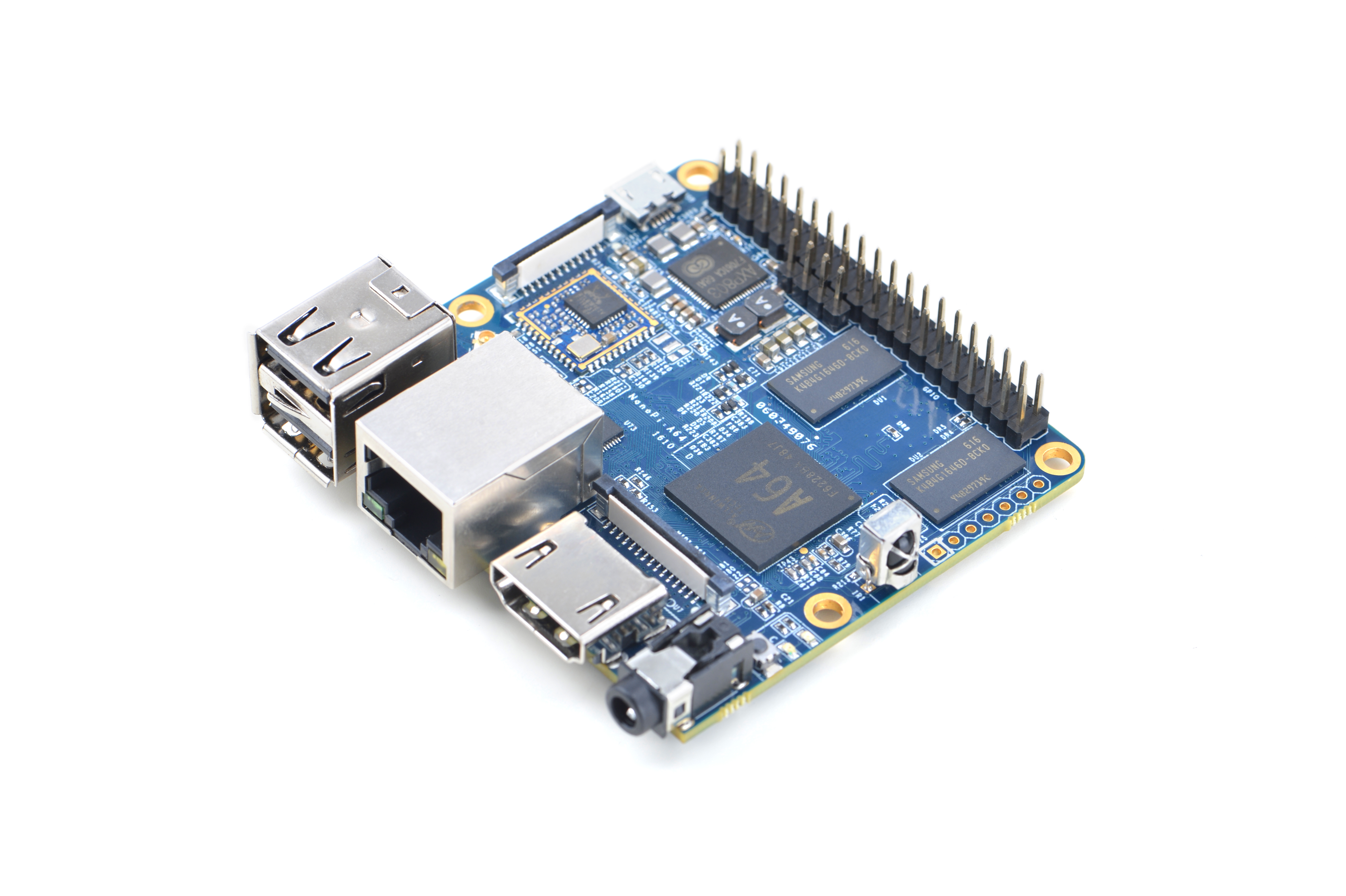
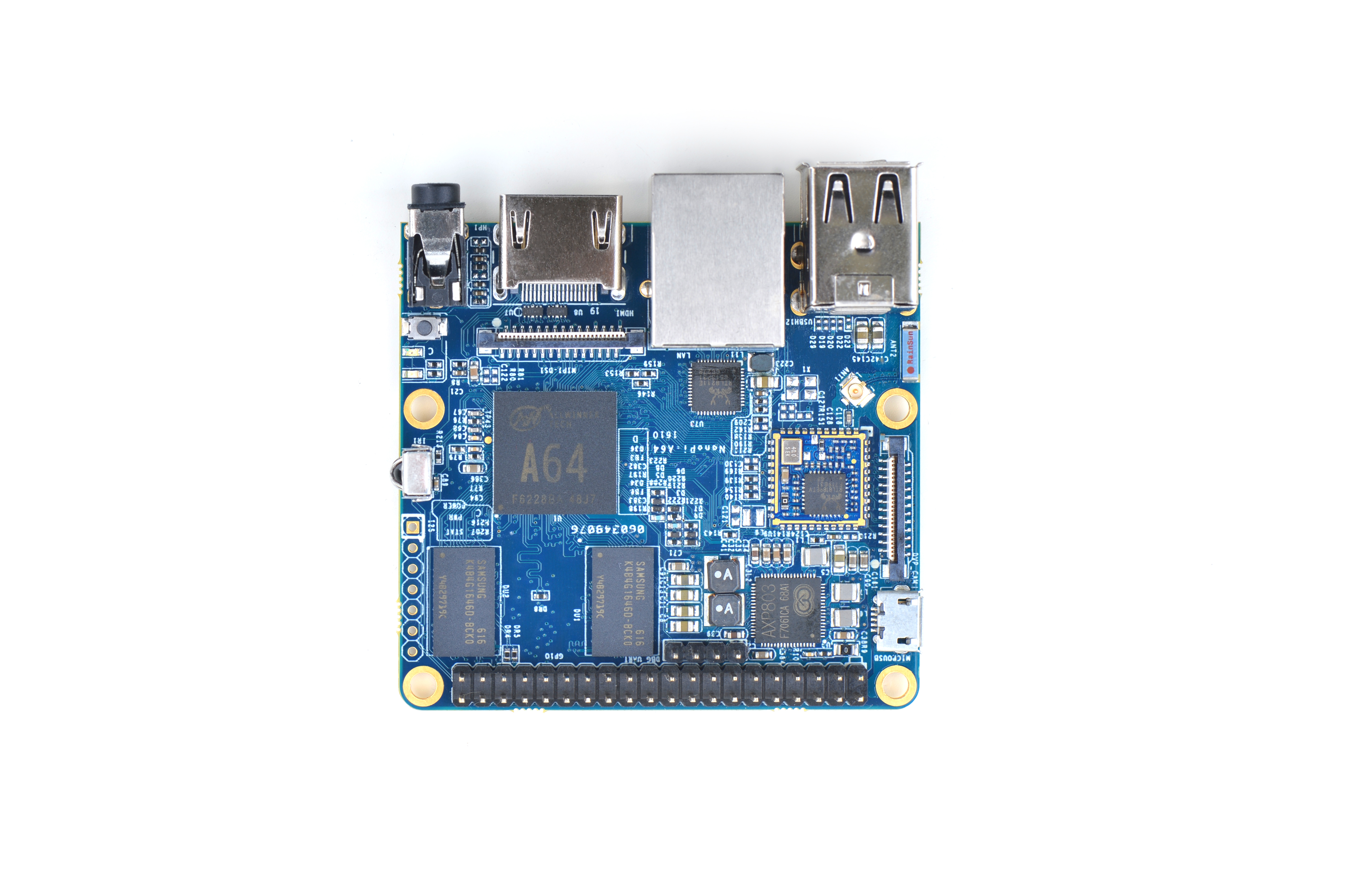
The NanoPi A64 is a new board of high performance with low cost designed by FriendlyElec. It uses Allwinner’s A64 quad-core SoC(ARM Cortex-A53). FriendlyElec has made a UbuntuCore and a UbuntuMATE image files for it.
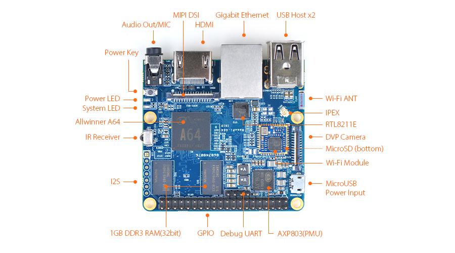
The NanoPi A64 is a small board with comprehensive interfaces, ports and features. It has Ethernet, IR receiver, Video/Audio input and output. It has onboard AXP803 PMU and WiFi. It takes power input from its MicroUSB port. It has MIPI-DSI and DVP interfaces, GPIO pin-header compatible with Raspberry Pi and a serial debug port.
2 Hardware Spec
- CPU: Allwinner A64, Quad-core Cortex-A53@648MHz to 1.152GHz, DVFS
- GPU: Mali400MP2, Supports OpenGL ES2.0, OpenVG1.1
- DDR3 RAM: 1GB
- Ethernet: One Gigabit Ethernet (RTL8211E)
- PMU Power Management: AXP803, support software power-off
- Wi-Fi: 802.11b/g/n
- Audio Out/MIC: 3.5mm audio jack
- IR Receiver: Onboard IR receiver
- USB 2.0 Type A x 2
- Serial Debug Port: 2.54mm pitch 4pin-header
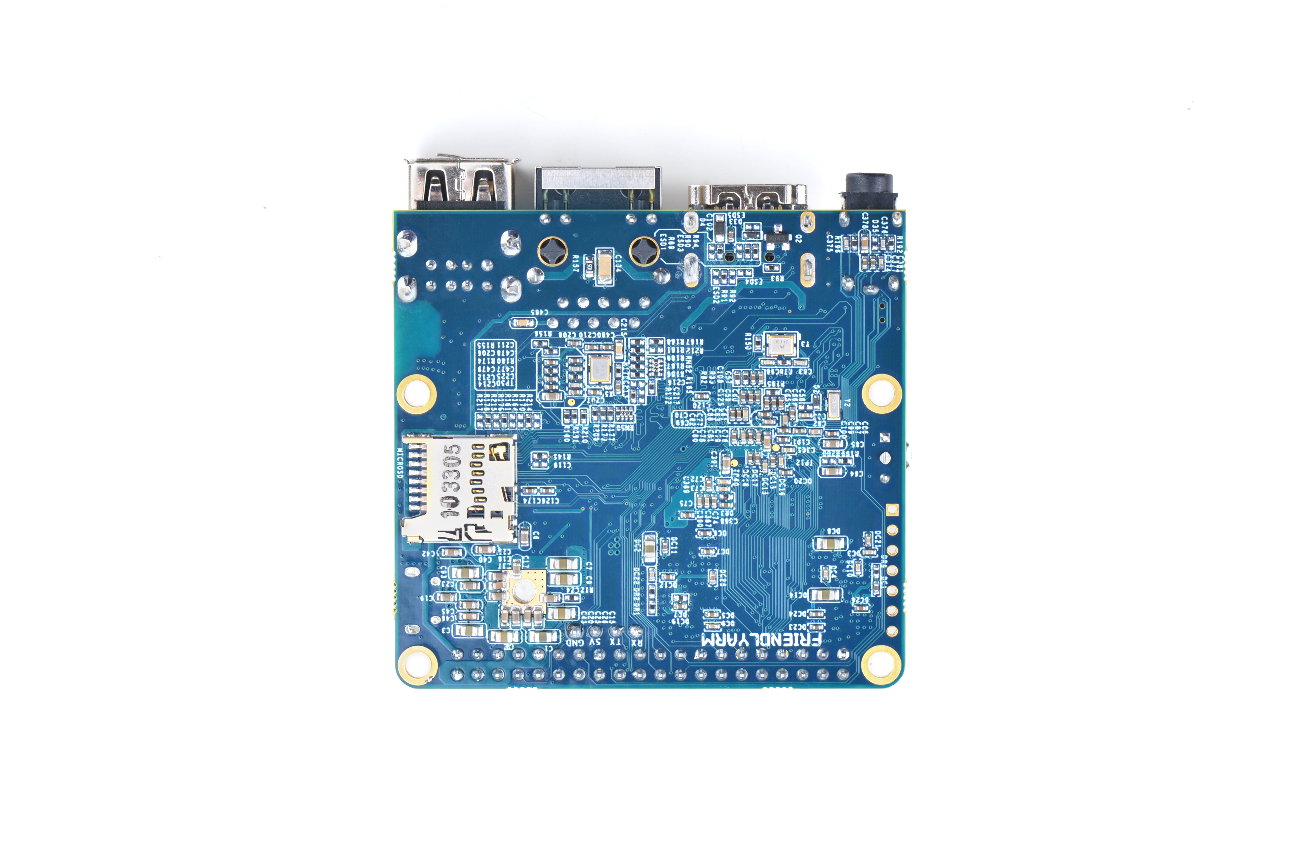
- microSD Slot x 1
- microUSB x 1: only for power input
- DVP Camera: 0.5mm pitch 24pin FPC seat
- Video Out: 1.4 HDMI Type-A
- MIPI DSI: 0.5mm pitch 30pin FPC seat
- GPIO: 2.54mm pitch 40pin-header, compatible with Raspberry Pi's GPIO. It includes UART, SPI, I2C, PWM, IO etc
- I2S: 7pin, 2.54mm pitch
- Power Button x 1
- LED: Power Indication x 1, System LED x 1
- PCB : Six layer, ENIG
- Dimension: 64 x 60mm
- Power: DC 5V/2A
- OS: Ubuntu-Core with QtE, Ubuntu-MATE
3 Diagram, Layout and Dimension
3.1 Layout
- GPIO Pin Description
Pin# Name Pin# Name 1 SYS_3.3V 2 VDD_5V 3 GPIOE15/I2C2_SDA 4 VDD_5V 5 GPIOE14/I2C2_SCL 6 GND 7 GPIOD7 8 GPIOH4/UART3-TX 9 GND 10 GPIOH5/UART3-RX 11 GPIOB0/UART2-TX 12 GPIOL10/PWM_S 13 GPIOL8/I2C_S_SCL 14 GND 15 GPIOL9/I2C_S_SDA 16 GPIOH6/UART3-RTS 17 SYS_3.3V 18 GPIOH7/UART3-CTS 19 GPIOC0/SPI0-MOSI 20 GND 21 GPIOC1/SPI0-MISO 22 GPIOB1/UART2-RX 23 GPIOC2/SPI0-CLK 24 GPIOC3/SPI0-CS 25 GND 26 GPIOH8/SPDIF-OUT 27 GPIOH3/I2C1_SDA 28 GPIOH2/I2C1_SCL 29 GOIOH10 30 GND 31 GOIOH11 32 GPIOD4 33 GPIOD5 34 GND 35 GPIOD3/SPI1-MISO 36 GPIOD0/SPI1-CS 37 GPIOD6 38 GPIOD2/SPI1-MOSI 39 GND 40 GPIOD1/SPI1-CLK
- Debug Port(UART0)
Pin# Name 1 GND 2 VDD_5V 3 UART0-TX 4 UART0-RX
- I2S/PCM Pin Description
Pin# Name 1 GND 2 SYS_3.3V 3 GPIOB5/PCM0-BCLK 4 GPIOB4/PCM0-SYNC 5 GPIOB6/PCM0-DOUT 6 GPIOB7/PCM0-DIN 7 GPIOB3/I2S0-MCLK
- DVP Camera IF Pin Description
Pin# Name Description 1, 2 SYS_3.3V 3.3V power output 7,9,13,15,24 GND Ground, 0V 3 CAM_SCL I2C Clock 4 CAM_SDA I2C Data 5 GPIOE17 Regular GPIO, control signals output to camera modules 6 GPIOE16 Regular GPIO, control signals output to camera modules 8 MCLK Clock signals output to camera modules 10 NC Not Connected 11 VSYNC Vertical synchronization to CPU from camera modules 12 HREF/HSYNC HREF/HSYNC signal to CPU from camera modules 14 PCLK PCLK signal to CPU from camera modules 16-23 Data bit7-0 data signals
- MIPI-DSI Pin Description
Pin# Name Description 1, 2, 3 VDD_5V 5V power output 4,7,9,11,14,15,18,21,24,27,30 GND Ground, 0V 5 I2C0_SDA I2C Clock 6 I2C0_SCL I2C Data 8 GPIOL7 Regular GPIO 10 GPIOB2 Regular GPIO 12 GPIOL12 Regular GPIO 13 AP-RESET# System Reset 16 MIPI-DSI-D3N MIPI DSI data, negative differential signal 17 MIPI-DSI-D3P MIPI DSI data, positive differential signal 19 MIPI-DSI-D2N MIPI DSI data, negative differential signal 20 MIPI-DSI-D2P MIPI DSI data, positive differential signal 22 MIPI-DSI-D1N MIPI DSI data, negative differential signal 23 MIPI-DSI-D1P MIPI DSI data, positive differential signal 25 MIPI-DSI-D0N MIPI DSI data, negative differential signal 26 MIPI-DSI-D0P MIPI DSI data, positive differential signal 28 MIPI-DSI-CKN MIPI DSI clock, negative differential signal 29 MIPI-DSI-CKP MIPI DSI clock, positive differential signal
- Note
- SYS_3.3V: 3.3V power output. In our test the real output was 3.1V
- VDD_5V: 5V power input/output. The input range is 4.7V ~ 5.6V. It can take power input from the MicroUSB or the VDD_5V pin from the Debug Port. The VDD_5V is connected to MicroUSB's VBUS
- All pins are 3.3V(In our test the real output was 3.1V), output current is 5mA
- For more details refer to the document schematics
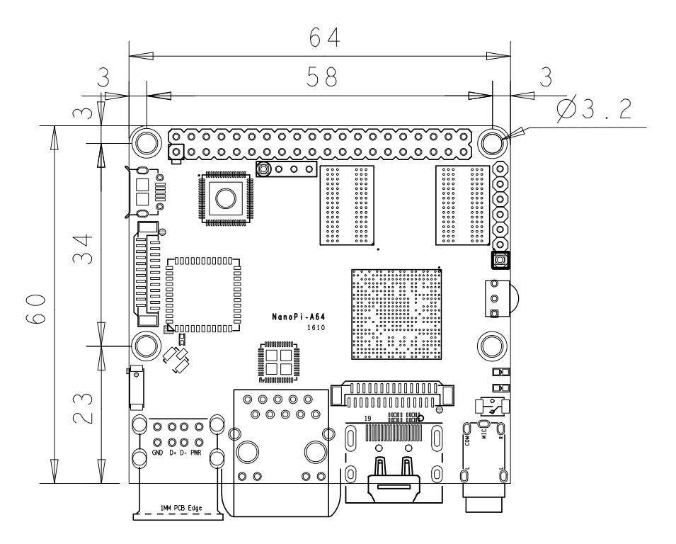
3.2 Dimensional Diagram
- For more details please refer to dimension file in dxf
4 Get Started
4.1 Essentials You Need
Before starting to use your NanoPi A64 get the following items ready
- NanoPi A64
- microSD Card/TFCard: Class 10 or Above, minimum 8GB SDHC
- microUSB power. A 5V/2A power is a must
- HDMI monitor
- USB keyboard and mouse, and a USB HUB would be better
- A Host computer running Ubuntu 14.04 64 bit system
4.2 TF Cards We Tested
To make your NanoPi A64 boot and run fast we highly recommend you use a Class10 8GB SDHC TF card or a better one. The following cards are what we used in all our test cases presented here:
- SanDisk TF 8G Class10 Micro/SD TF card:
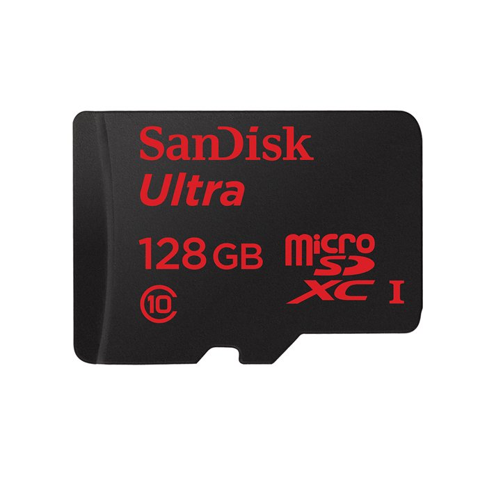
- SanDisk TF128G MicroSDXC TF 128G Class10 48MB/S:
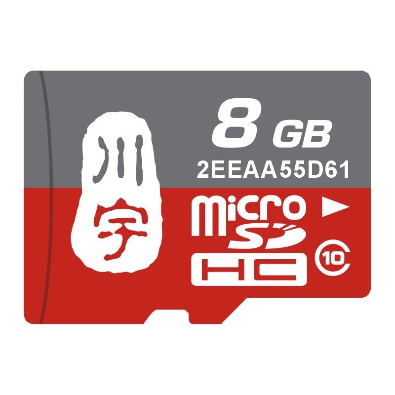
- 川宇 8G C10 High Speed class10 micro SD card:
4.3 Make an Installation TF Card
4.3.1 Get Image File
Get the following files from download link to download image files (under the officail-ROMs directory) and the flashing utility(under the tools directory):
Image Files nanopi-a64-core-qte-sd4g.img.zip a Light Ubuntu-core system with a Qt Embedded GUI library nanopi-a64-ubuntu-mate-sd4g.img.zip Ubuntu with a MATE-desktop Flash Utility: win32diskimager.rar Windows utility. Under Linux users can use "dd" PhoenixCard_V310.rar Windows utility for flashing Android image. Attention: the "dd" command under Linux doesn't work for flashing Android image HDDLLF.4.40.exe Windows utility for formatting a TF card
4.3.2 Make Ubuntu-Core Image Card
- Extract the nanopi-a64-core-qte-sd4g.img.zip and win32diskimager.rar files. Insert a TF card(at least 4G) into a Windows PC and run the win32diskimager utility as administrator. On the utility's main window select your TF card's drive, the wanted image file and click on "write" to start flashing the TF card.
- After this writing process is done insert this card into your NanoPi A64's TF card slot and power on (with a 5V/2A power source). If the green LED is on and the blue LED is blinking this indicates your NanoPi A64 has successfully booted.
5 Work with Ubuntu-Core
5.1 Run Ubuntu-Core
- Insert a TF card with UbuntuCore image files into your NanoPi A64, connect the board to a 5V/2A power source the board will be automatically powered on. If you can see the blue LED flashing it means your board is working and UbuntuCore is being loaded.
1) To make it easy you can connect an HDMI monitor, a USB mouse and keyboard to your A64 board.
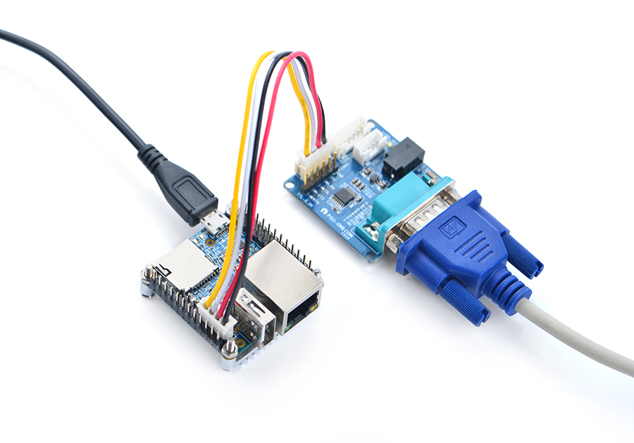
2) If you want to do kernel development you need to use a serial communication board, ie a PSU-ONECOM board, which will allow you to operate the board via a serial terminal.
- Here is a setup where we connect a NanoPi A64 to a PC via the PSU-ONECOM and you can power on your A64 from either the PSU-ONECOM or the board's MicroUSB:
- It has two user names: root and fa and the password for both is "fa".
- Update packages
sudo apt-get update
5.2 Extend TF Card's Section
We strongly recommend you to do this right after you have made an installation TF card since this will greatly enhance your A64's experience
- Extend your card's rootfs section under a host PC:
sudo umount /dev/sdx?
sudo parted /dev/sdx unit % resizepart 2 100 unit MB print
sudo resize2fs -f /dev/sdx2
Note: you need to replace "/dev/sdx" with the device name in your system.
5.3 Login via SSH
If your NanoPi A64 is connected to a network via Ethernet before it is powered on it will automatically obtain an IP after it is powered up. If it is not connected via Ethernet or its DHCP is not activated obtaining an IP will fail and system will hang on for about 15 to 60 seconds. You can log into the board via SSH. In our test the IP address detected by our router was 192.168.1.230 and we ran the following command to log into the NanoPi NEO:
ssh root@192.168.1.230
The password is fa。
5.4 HDMI输出声音
Ubuntu-core系统默认从3.5mm耳机座输出声音,想从HDMI输出需要修改文件系统上的配置文件/etc/asound.conf如下:
pcm.!default {
    type hw
    card 1
    device 0
}

ctl.!default {
    type hw
    card 1
}
card 0代表3.5mm耳机孔,card 1代表HDMI音频。设置完成后需要重启系统才能生效。
5.5 连接WiFi
用vi或在图形界面下用gedit编辑文件 /etc/wpa_supplicant/wpa_supplicant.conf, 在文件末尾填入路由器信息如下所示:
network={
        ssid="YourWiFiESSID"
        psk="YourWiFiPassword"
}
其中,YourWiFiESSID和YourWiFiPassword请替换成你要连接的无线AP名称和密码。
保存退出后,执行以下命令即可连接WiFi:
ifdown wlan0
ifup wlan0
如果你的WiFi密码中有特殊字符,或者你不希望明文存放密码,你可以使用wpa_passphrase命令为WiFi密码生成一个密钥(psk),用密钥来代替密码 ,在命令行下,可输入以下命令生成密钥:
wpa_passphrase YourWiFiESSID
在提示输入密码时,输入你的WiFi密码,再打开 /etc/wpa_supplicant/wpa_supplicant.conf 文件你会发现密钥已经被更新,你可以删除明文的密码了。
5.6 查看CPU工作温度
获取CPU核心的当前温度值、运行频率等信息:
cpu_freq
