Matrix - Sound Sensor
From FriendlyELEC WiKi
Contents
1 Introduction
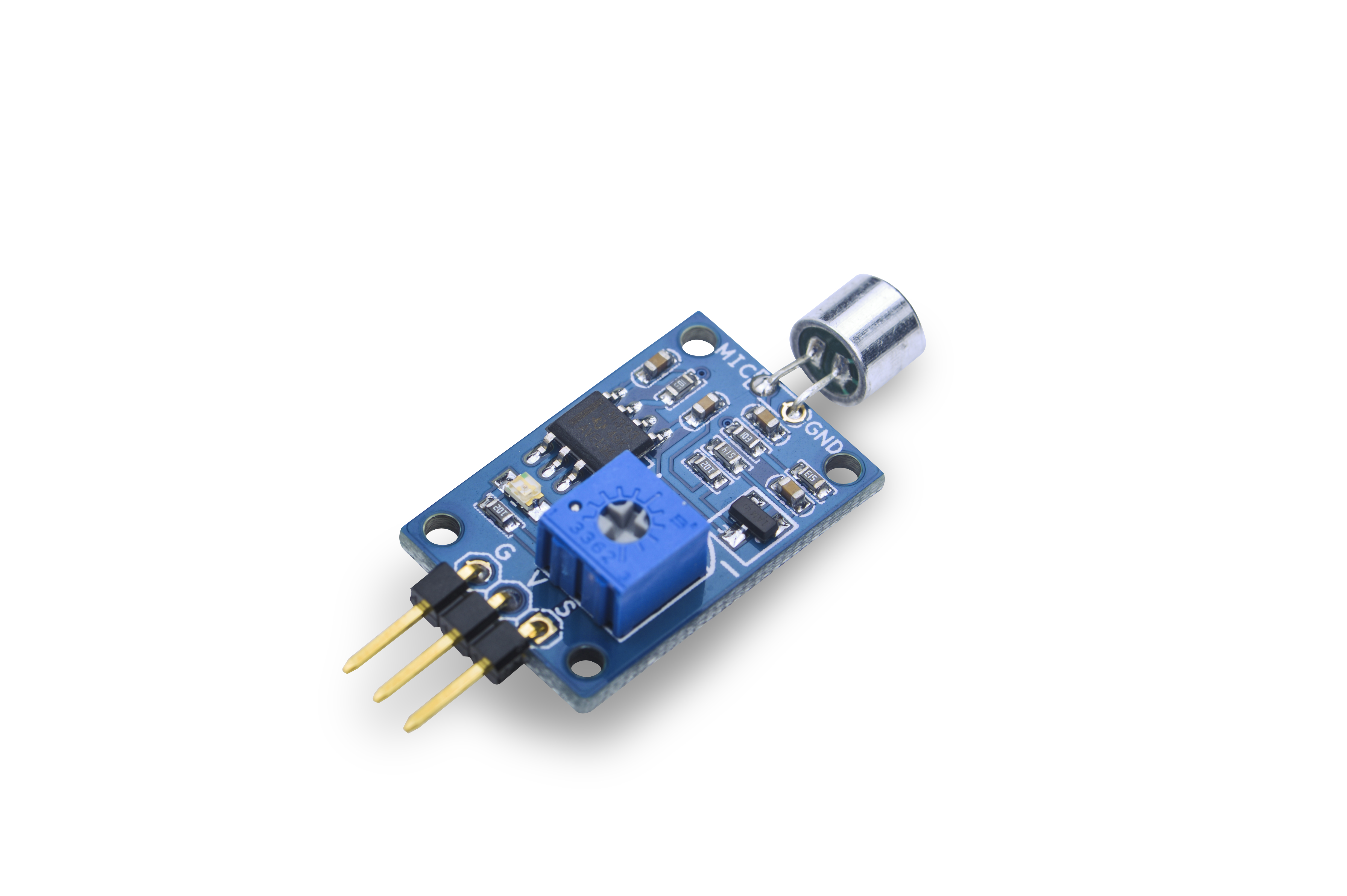
- The Matrix-Sound_Sensor module is used to detect sound.
- The module has a variable resistor which can be used to control the threshold value of a sound level. Only when a sound level's value is greater than this threshold the module can detect it. Turning clockwise increases this threshold value. Turning anticlockwise decreases this value.
- By default this module's output level is high. When it detects sound signals its output level will turn low. When sound signals are not detected its output will turn high again without time delay.
2 Features
- Variable threshold value
- 2.54mm spacing pin interface
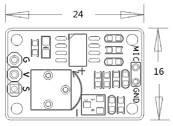
- PCB dimension (mm): 16 x 24
- Pin Description:
| Pin | Description |
| S | GPIO |
| V | Supply Voltage 5V |
| G | Ground |
3 Basic Device Operation
- The module contains an electret condenser microphone. Sound waves impinging on the diaphragm cause the capacitance between it and the back plate to change synchronously, this in turn induces an AC voltage on the back plate.
- This sound sensor functions like a microphone which receives sound waves and convert them to images which show the sound waves' vibration. When it receives a sound wave it will output 1 but cannot measure its strength.
4 Applications
4.1 Connect to NanoPi M1
Refer to the following connection diagram to connect the module to the NanoPi M1:
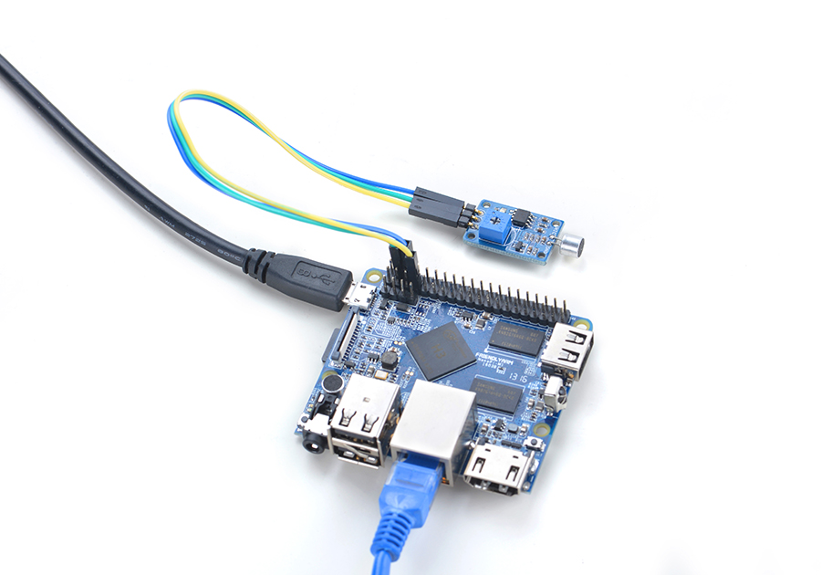
Connection Details:
| Matrix-Sound_Sensor | NanoPi M1 |
| S | Pin7 |
| V | Pin4 |
| G | Pin6 |
4.2 Connect to NanoPi 2
Refer to the following connection diagram to connect the module to the NanoPi 2:
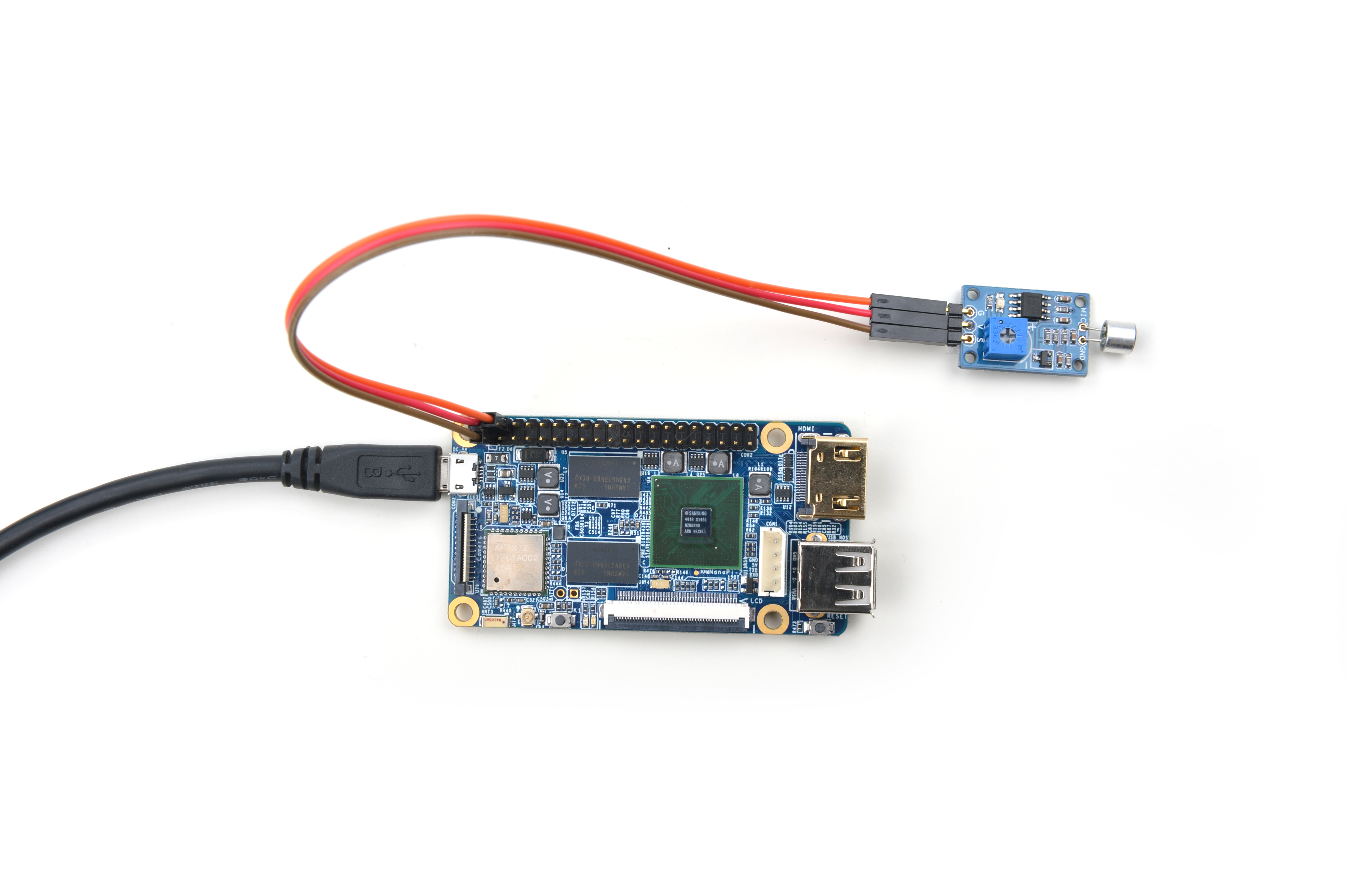
Connection Details:
| Matrix-Sound_Sensor | NanoPi 2 |
| S | Pin7 |
| V | Pin4 |
| G | Pin6 |
4.3 Connect to NanoPi M2 / NanoPi 2 Fire
Refer to the following connection diagram to connect the module to the NanoPi M2/ NanoPi 2 Fire:
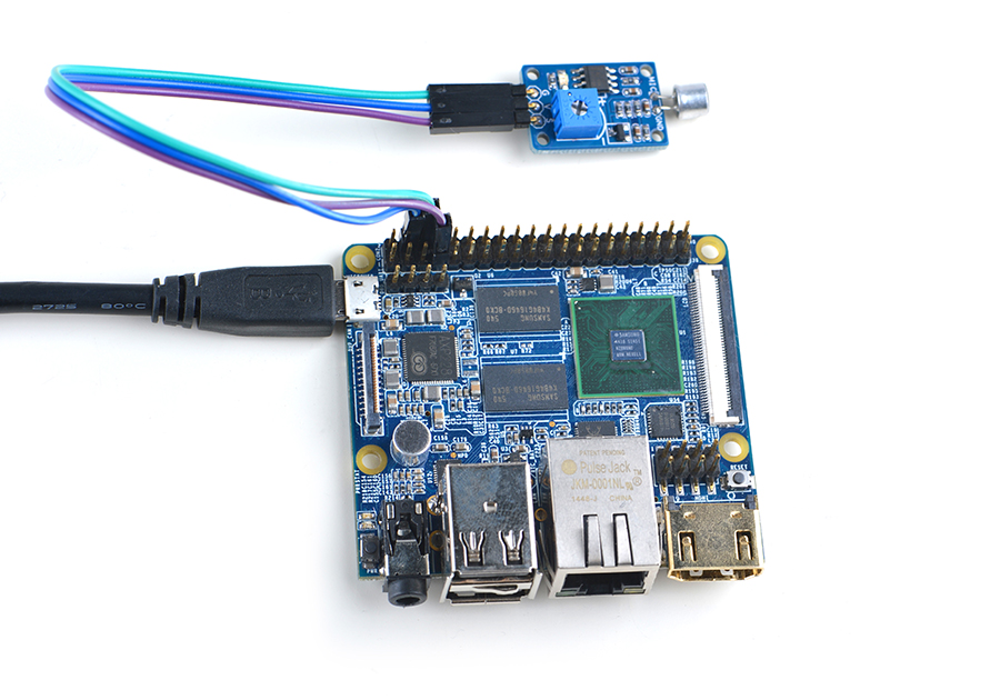
Connection Details:
| Matrix-Sound_Sensor | NanoPi M2 |
| S | Pin7 |
| V | Pin4 |
| G | Pin6 |
4.4 Connect to NanoPC-T2
Refer to the following connection diagram to connect the module to the NanoPC-T2:
Matrix-Sound_Sensor_NanoPC-T2
Connection Details:
| Matrix-Sound_Sensor | NanoPC-T2 |
| S | Pin15 |
| V | Pin29 |
| G | Pin30 |
5 编译运行测试程序
启动开发板并运行Debian系统,进入系统后克隆Matrix代码仓库:
$ apt-get update && apt-get install git
$ git clone https://github.com/friendlyarm/matrix.git
克隆完成后会得到一个名为matrix的目录。
编译并安装Matrix:
$ cd matrix
$ make && make install
运行测试程序:
$ matrix-gpio_int注意:此模块并不支持热插拔,启动系统前需要确保硬件连接正确。
运行效果如下:
Waiting event...
Device[0] value is 1
当周围环境有声音时会检测到事件。
6 代码说明
所有的开发板都共用一套Matrix代码,本模块的测试示例代码为matrix-gpio_int,内容如下:
int main(int argc, char ** argv)
{
    int i, board;
    int retSize = -1;
    char value[ARRAY_SIZE(dev)];

    if ((board = boardInit()) < 0) {
        printf("Fail to init board\n");
        return -1;
    }

    if (argc == 2)
        dev[0].pin = atoi(argv[1]);
    system("modprobe "DRIVER_MODULE);
    signal(SIGINT, intHandler);
    if (board == BOARD_NANOPI_T2)
        dev[0].pin = GPIO_PIN(15);
    printf("Use GPIO_PIN(%d)\n", dev[0].pin);
    if ((devFD =sensorInit(dev, ARRAY_SIZE(dev))) == -1) {
        printf("Fail to init sensor\n");
        goto err;
    }
    printf("Waiting event...\n");
    if ((retSize = sensorRead(devFD, value, ARRAY_SIZE(dev))) == -1) {
        printf("Fail to read sensors\n");
    }
    if (retSize > 0) {
        i = 0;
        for (i=0; i<retSize; i++) {
            printf("Device[%d] value is %d\n", i, value[i]);
        }
    }
    sensorDeinit(devFD);
err:
    system("rmmod "DRIVER_MODULE);
    return 0;
}
API说明参考维基:Matrix API reference manual
7 Resources
8 Update Log
8.1 Feb-23-2016
- Added the description for "NanoPi 2 branch" in Section 4
- Added Section 5: Connect to NanoPi 2
