NanoPi R4S/zh
Contents
- 1 Introduction
- 2 Hardware Spec
- 3 Diagram, Layout and Dimension
- 4 Get Started
- 5 Work with FriendlyWrt
- 5.1 Introduction to FriendlyWrt
- 5.2 First boot
- 5.3 Account & Password
- 5.4 Network Connection
- 5.5 Login FriendlyWrt
- 5.6 Recommended security settings
- 5.7 Safe shutdown operation
- 5.8 Install Software Packages
- 5.9 Disable IPv6
- 5.10 Configure the function of the user button
- 5.11 Some common issues of FriendlyWrt
- 5.12 Let FriendlyWrt regenerate network settings
- 5.13 Use USB2LCD to view IP and temperature
- 5.14 How to Control Fan Speed for Cooling
- 5.15 Work with USB WiFi Device
- 5.16 Work with Docker Applications
- 5.17 Mount smbfs
- 5.18 Use sdk to compile the package
- 5.19 Serial port debug
- 6 Compile FriendlyWrt
- 7 Work with FriendlyCore
- 8 Make Your Own OS Image
- 9 Link to Rockchip Resources
- 10 Schematic, PCB CAD File
1 Introduction
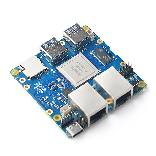
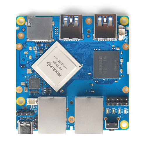
- The NanoPi R4S is a RK3399 SoC based ARM board.
2 Hardware Spec
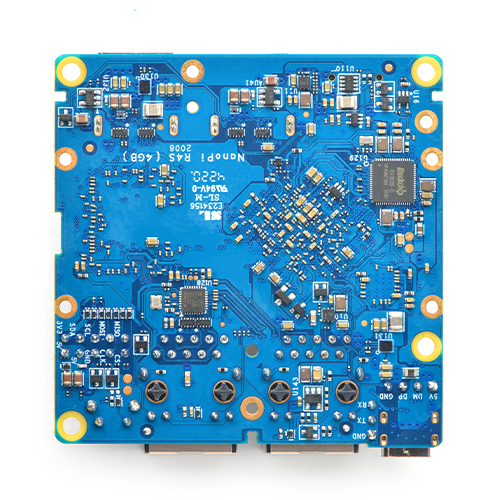
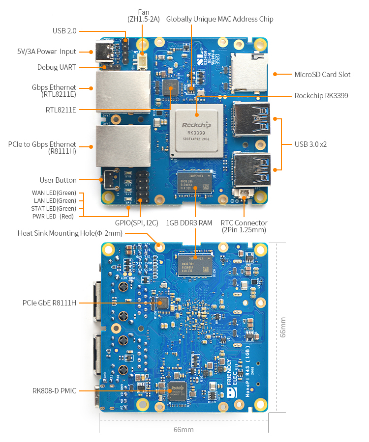
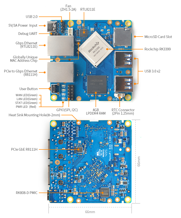
- SoC: Rockchip RK3399
- CPU: big.LITTLE,Dual-Core Cortex-A72(up to 2.0GHz) + Quad-Core Cortex-A53(up to 1.5GHz)
- GPU: Mali-T864 GPU,supports OpenGL ES1.1/2.0/3.0/3.1, OpenCL, DX11, and AFBC
- VPU: 4K VP9 and 4K 10bits H265/H264 60fps decoding, Dual VOP, etc
- PMU: RK808-D PMIC, cooperated with independent DC/DC, enabling DVFS, software power-down, RTC wake-up, system sleep mode
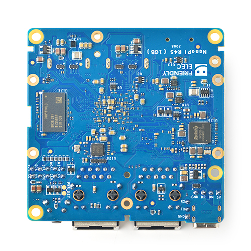
- RAM: 1GB DDR3/4GB LPDDR4
- Flash: no Onboard eMMC
- Ethernet: one Native Gigabit Ethernet, and one PCIe Gigabit Ethernet
- USB: two USB 3.0 Type-A ports
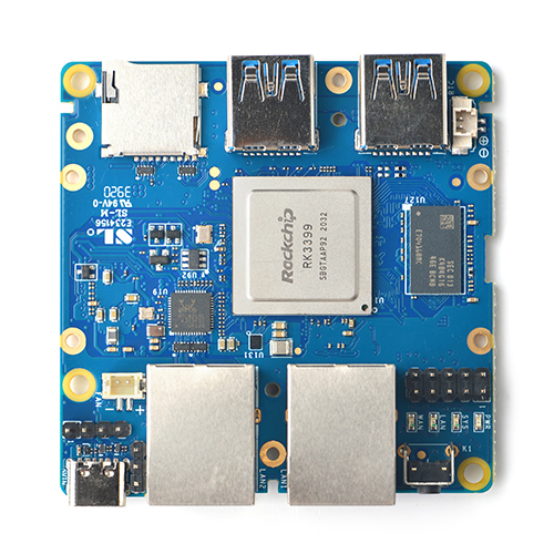
- Pin header extension interface
- 2x5-pin header: SPI x 1, I2C x 1
- 4-pin header: USB 2.0
- microSD Slot x 1
- Debug: one Debug UART, 3 Pin 2.54mm header, 3V level, 1500000bps
- LEDs: 1 x power LED and 3 x GPIO Controlled LED (SYS, LAN, WAN)
- others:
- 2 Pin 1.27/1.25mm RTC battery input connector
- one User Button
- one 5V Fan connector
- Power supply: DC 5V/3A, via USB-C connector or Pin header
- PCB: 8 Layer, 66 mm x 66 mm
- Ambient Operating Temperature: -20℃ to 70℃
3 Diagram, Layout and Dimension
3.1 Layout
- 2x5-pin header
Pin# Assignment Pin# Assignment 1 VDD_5V 2 VDD_3.3V 3 VDD_5V 4 I2C3_SDA 5 GND 6 I2C3_SCL 7 SPI1_CLK 8 SPI1_MOSI 9 SPI1_CS 10 SPI1_MISO
- 4-pin header
1 2 3 4 VDD_5V USB_DM USB_DP GND
- Debug UART Pin Spec
- 3V level signals, 1500000bps
Pin# Assignment Description 1 GND 0V 2 UART2DBG_TX output 3 UART2DBG_RX intput
- USB Port
- Each USB 3.0 port has 2A overcurrent protection.
- RTC
- RTC backup current is 27uA.
- Connector P/N: Molex 53398-0271
- Notes
- Power Input : 5V/3A, via USB Type-C(USB PD Specification is not supported) or Pin1&Pin2 of the 2x5-pin header
4 Get Started
4.1 Essentials You Need
Before starting to use your NanoPi R4S get the following items ready
- NanoPi R4S
- MicroSD Card/TF Card: Class 10 or Above, minimum 8GB SDHC
- MicroUSB 5V/2A power adapter
- A host computer running Ubuntu 18.04 64-bit system
4.2 Install OS
4.2.1 Download Image Files
Go to download link to download the image files under the officail-ROMs directory and the flashing utility under the tools directory:
Image Files: rk3399-sd-friendlycore-focal-4.19-arm64-YYYYMMDD.img.zip Based on UbuntuCore 20.04 and Linux-4.19 Kernel rk3399-sd-friendlywrt-5.4-YYYYMMDD.img.zip Based on OpenWrt and Linux-5.4 Kernel Flashing Utility: win32diskimager.rar Windows utility. Under Linux users can use "dd"
4.2.2 Linux
4.2.2.1 Flash to TF
- FriendlyCore / Debian / Ubuntu / OpenWrt / DietPi are all based on a same Linux distribution and their installation methods are the same.
- Extract the Linux image and win32diskimager.rar files. Insert a TF card(at least 8G) into a Windows PC and run the win32diskimager utility as administrator. On the utility's main window select your TF card's drive, the wanted image file and click on "write" to start flashing the TF card.
After it is installed you will see the following window:

- Insert this card into your board's BOOT slot and power on (with a 5V/2A power source). If the PWR LED is on and the STAT LED is blinking this indicates your board has successfully booted.
;
5 Work with FriendlyWrt
5.1 Introduction to FriendlyWrt
FriendlyWrt is a customized system made by FriendlyElec based on an OpenWrt distribution. It is open source and well suitable for developing IoT applications, NAS applications etc.
5.2 First boot
For the first boot, the system needs to do the following initialization work:
1)Extended root file system
2)Initial setup(will execute /root/setup.sh)
So you need to wait for a while (about 2~3 minutes) to boot up for the first time, and then set FriendlyWrt, you can enter the ttyd terminal on the openwrt webpage, when the prompt is displayed as root@FriendlyWrt, it means the system has been initialized.
root@FriendlyWrt
5.3 Account & Password
The default password is password (empty password in some versions). Please set or change a safer password for web login and ssh login. It is recommended to complete this setting before connecting NanoPi-R4S to the Internet.
5.4 Network Connection
Use a network cable to connect NanoPi-R4S's WAN to a master router and the board will get an IP address via DHCP. Login into the router and check NanoPi-R4S's IP address.
5.5 Login FriendlyWrt
Connect the PC to the LAN port of NanoPi-R4S. If your PC without a built-in ethernet port, connect the LAN port of the wireless AP to the LAN port of NanoPi-R4S, and then connect your PC to the wireless AP via WiFi , Enter the following URL on your PC's browser to access the admin page:
- http://friendlywrt/
- http://192.168.2.1/
- http://[fd00:ab:cd::1]
The above is the LAN port address of NanoPi-R4S. The IP address of the WAN port will be dynamically obtained from your main router through DHCP.
5.6 Recommended security settings
The following settings are highly recommended to complete before connecting NanoPi-R4S to the Internet。
- Set a secure password
- Only allow access to ssh from lan, change the port
5.7 Safe shutdown operation
Enter the ttyd terminal, enter the poweroff command and hit enter, wait until the led light is off, and then unplug the power supply.
5.8 Install Software Packages
5.8.1 Update Package List
Before install software packages update the package list:
$ opkg update
5.8.2 List Available Packages
$ opkg list
5.8.3 List Installed Packages
$ opkg list-installed
5.8.4 Install Packages
$ opkg install <package names>
5.8.5 Remove Packages
$ opkg remove <package names>
5.9 Disable IPv6
sed -i -e "s/DISABLE_IPV6=0/DISABLE_IPV6=1/g" /root/setup.sh
rm -rf /etc/board.json /etc/config/system /etc/config/network /etc/config/wireless /etc/firstboot_* /root/.friendlyelec
reboot
5.10 Configure the function of the user button
By default, the user button is configured to reboot the device, as shown below:
echo 'BTN_1 1 /sbin/reboot' >> /etc/triggerhappy/triggers.d/example.conf
You can change its behavior by changing the configuration file above.
5.11 Some common issues of FriendlyWrt
- Unable to dial up
- Go to "Network" -> "Firewall" and set "Inbound Data", "Outbound Data" and "Forwarding" in "WAN Zone" to "Accept";
- If you still cannot access the Internet, you can try to turn off IPV6;
- Unable to power on
- Try to replace the power adapter and cable. It is recommended to use a power supply with specifications above 5V/2A;
- Note that some fast chargers with Type-C interface will have a delay, it may take a few seconds to start providing power;
- When doing secondary routing, the computer cannot connect to the Internet
- If your main network is IPv4, and NanoPi-R4S works in IPv6, the computer may not be able to connect to the Internet. It is recommended to turn off IPv6 (the method is described later in this WiKi), or switch the main route to IPv6;
- If you have questions or have better suggestions, please send an email to techsupport@friendlyarm.com;
5.12 Let FriendlyWrt regenerate network settings
This method will trigger FriendlyWrt to re-identify the hardware model and generate the network configuration under /etc/config, which is similar but not completely equivalent to restoring factory settings:
rm -rf /etc/board.json /etc/config/system /etc/config/network /etc/config/wireless /etc/firstboot_* /root/.friendlyelec
reboot
The /root/setup.sh initialization script will be executed again at the next boot, so you can debug the /root/setup.sh script through this method.
5.13 Use USB2LCD to view IP and temperature
Plug the USB2LCD module to the USB interface ofNanoPi-R4S and power on, the IP address and CPU temperature will be displayed on the LCD:
5.14 How to Control Fan Speed for Cooling
(Note: The contents of this section are based on firmware released after 2021/08/31, kernel version kernel 5.10.xyz)
- The default behavior of the current PWM fan is: after a short wait (about 20 seconds) for power on, the fan will first work automatically for about 5 seconds, after which the behavior is driven by the kernel, which decides the fan on/off and the speed according to the CPU temperature.
- The behavior of the fan can be changed by modifying the following script: /usr/bin/fa-fancontrol.sh. For example, to change the CPU temperature when the fan starts working, you can change the following two lines:
echo 50000 > trip_point_3_temp  # Indicates that the fan starts working at the lowest speed when the CPU temperature reaches 50 degrees
echo 55000 > trip_point_4_temp  # Indicates that when the CPU temperature reaches 55 degrees, the fan rises to the second gear and above and automatically adjusts to the highest gear (4th gear) or reduces the speed according to the CPU cooling situation
- If you need to adjust the speed of each gear, you can modify the kernel dts file and recompile the kernel to achieve the purpose, the specific dts and modified location can be referred to the following commit: https://github.com/friendlyarm/kernel-rockchip/commit/f74ac319f02e2d22cdd33227e7f167e4232809f9
As shown below, the cooling-levels define 4 levels, with 0 being off and the highest level being 255:
	fan: pwm-fan {
 		compatible = "pwm-fan";
-		/* FIXME: adjust leveles for the connected fan */
-		cooling-levels = <0 12 18 255>;
+ cooling-levels = <0 18 102 170 255>;- If you are using kernel version 4.19.xyz, the fan is operated by PWM at the application level to achieve temperature control, the above content is not applicable, you need to modify this script:
/usr/bin/fa-fancontrol-direct.sh
5.15 Work with USB WiFi Device
5.15.1 Check USB WiFi Device with Command Line Utility
(1) Click on "services>ttyd" to start the command line utility
(2) Make sure no USB devices are connected to your board and run the following command to check if any USB devices are connected or not
lsusb
(3) Connect a USB WiFi device to the board and run the command again
lsusb
You will see a new device is detected. In our test the device's ID was 0BDA:C811
(4) Type your device's ID (in our case it was "0BDA:C811" or "VID_0BDA&PID_C811") in a search engine and you may find a device that matches the ID. In our case the device we got was Realtek 8811CU.
5.15.2 Configure a USB WiFi Device as AP
(1) Connect a USB WiFi device to the NanoPi-R4S. We recommend you to use the following devices:
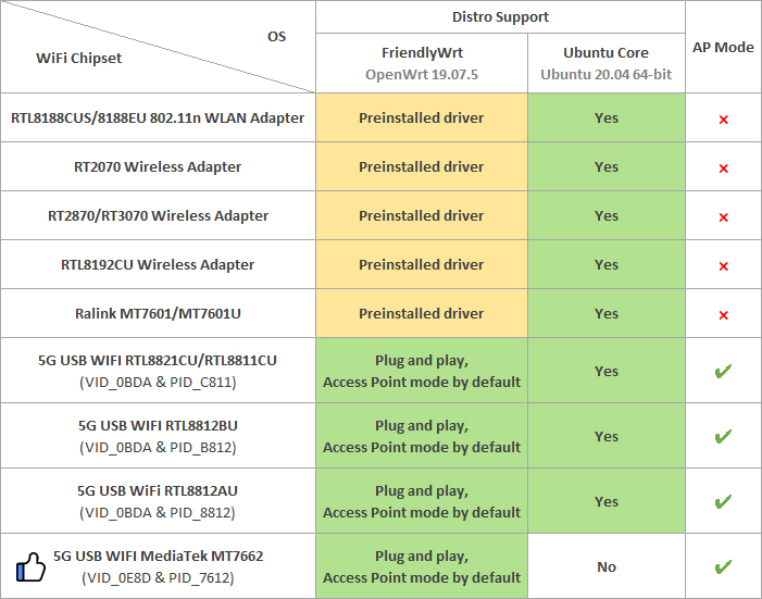
Note: devices that match these VID&PIDs would most likely work.
(2) Click on "System>Reboot" and reboot your NanoPi-R4S
(3) Click on "Network>Wireless" to enter the WiFi configuration page
(4) Click on "Edit" to edit the configuration
(5) On the "Interface Configuration" page you can set the WiFi mode and SSID, and then go to "Wireless Security" to change the password. By default the password is "password". After you make your changes click on "Save" to save
(6) After you change the settings you can use a smartphone or PC to search for WiFi
5.15.3 Common USB WiFi issues
1) It is recommended to plug in the usb wifi in the off state, then power it on, FriendlyWrt will automatically generate the configuration file /etc/config/wireless, if not, see if there is wlan0 by ifconfig -a, if there is no wlan0, usually there is no driver.
2) If ifconfig -a sees wlan0, but the hotspot is not working properly, try changing the channel and country code, an inappropriate country code can also cause the WiFi to not work.
3) Some USB WiFis (e.g. MTK MT7662) work in CD-ROM mode by default and need to be switched by usb_modeswitch, you can try to add usb_modeswitch configuration to the following directory: /etc/usb_modeswitch.d.
5.16 Work with Docker Applications
5.16.1 Work with Docker: Install JellyFin
mkdir -p /jellyfin/config
mkdir -p /jellyfin/videos
docker run --restart=always -d -p 8096:8096 -v /jellyfin/config:/config -v /jellyfin/videos:/videos jellyfin/jellyfin:10.1.0-arm64 -name myjellyfin
After installation, visit port 8096 and here is what you would find:

5.16.2 Work with Docker: Install Personal Nextcloud
mkdir /nextcloud -p
docker run -d -p 8888:80  --name nextcloud  -v /nextcloud/:/var/www/html/ --restart=always --privileged=true  arm64v8/nextcloud
After installtion, visit port 8888.
5.17 Mount smbfs
mount -t cifs //192.168.1.10/shared /movie -o username=xxx,password=yyy,file_mode=0644
5.18 Use sdk to compile the package
5.18.1 Install the compilation environment
Download and run the following script on 64-bit Ubuntu (version 18.04+): How to setup the Compiling Environment on Ubuntu bionic
5.18.2 Download and decompress sdk from the network disk
The sdk is located in the toolchain directory of the network disk:
tar xvf ~/dvd/FriendlyELEC-NanoPiR4S/toolchain/friendlywrt/openwrt-sdk-19.07.5-rockchip-rk3399_gcc-7.5.0_musl.Linux-x86_64.tar.xz
# If the path is too long, it will cause some package compilation errors, so change the directory name here
mv openwrt-sdk-19.07.5-rockchip-rk3399_gcc-7.5.0_musl.Linux-x86_64 sdk
cd sdk
./scripts/feeds update -a
./scripts/feeds install -a
5.18.3 Compile the package
download the source code of the example (a total of 3 examples are example1, example2, example3), and copy to the package directory:
git clone https://github.com/mwarning/openwrt-examples.git
cp -rf openwrt-examples/example* package/
rm -rf openwrt-examples/
Then enter the configuration menu through the following command:
make menuconfigIn the menu, select the following packages we want to compile (actually selected by default):
"Utilities" => "example1"
"Utilities" => "example3"
"Network" => "VPN" => "example2"
execute the following commands to compile the three software packages:
make package/example1/compile V=99
make package/example2/compile V=99
make package/example3/compile V=99
After the compilation is successful, you can find the ipk file in the bin directory, as shown below:
$ find ./bin -name example*.ipk
./bin/packages/aarch64_cortex-a53/base/example2_0.1-1_aarch64_cortex-a53.ipk
./bin/packages/aarch64_cortex-a53/base/example3_0.1-1_aarch64_cortex-a53.ipk
./bin/packages/aarch64_cortex-a53/base/example1_0.1-1_aarch64_cortex-a53.ipk
5.18.4 Install the ipk to NanoPi
You can use the scp command to upload the ipk file to NanoPi:
cd ./bin/packages/aarch64_cortex-a53/base/
scp example*.ipk root@192.168.2.1:/root/
Then use the opkg command to install them:
cd /root/
opkg install example2_0.1-1_aarch64_cortex-a53.ipk
opkg install example3_0.1-1_aarch64_cortex-a53.ipk
opkg install example1_0.1-1_aarch64_cortex-a53.ipk
5.19 Serial port debug
Connect to NanoPi R4S with screen :
screen /dev/ttyUSB0 1500000 8N1
6 Compile FriendlyWrt
6.1 Download Code
mkdir friendlywrt-rk3399
cd friendlywrt-rk3399
repo init -u https://github.com/friendlyarm/friendlywrt_manifests -b master-v19.07.4 -m rk3399.xml --repo-url=https://github.com/friendlyarm/repo  --no-clone-bundle
repo sync -c  --no-clone-bundle
6.2 1-key Compile
./build.sh nanopi_r4s.mkAll the components (including u-boot, kernel, and friendlywrt) are compiled and the sd card image will be generated.
7 Work with FriendlyCore
7.1 FriendlyCore User Account
- Non-root User:
   User Name: pi
   Password: pi
- Root:
   User Name: root
   Password: fa
7.2 Update Software Packages
$ sudo apt-get update
7.3 Setup Network Configurations
7.3.1 Set static IP address
By default "eth0" is assigned an IP address obtained via dhcp. If you want to change the setting you need to change the following file:
vi /etc/network/interfaces.d/eth0
For example if you want to assign a static IP to it you can run the following commands:
auto eth0
iface eth0 inet static
    address 192.168.1.231
    netmask 255.255.255.0
    gateway 192.168.1.1
7.3.2 Set a DNS
You also need to modify the following file to add the DNS configuration:
vi /etc/systemd/resolved.conf
For example, set to 192.168.1.1:
[Resolve]
DNS=192.168.1.1
Restart the systemd-resolved service with the following command:
sudo systemctl restart systemd-resolved.service
sudo systemctl enable systemd-resolved.service
7.3.3 Set up to use another network interface
To change the setting of "eth1" you can add a new file similar to eth0's configuration file under the /etc/network/interfaces.d/ directory.
7.4 Setup Wi-Fi
First, use the following command to check if Network-Manager is installed on your system:
which nmcliIf you have installed it, refer to this link to connect to WiFi: Use NetworkManager to configure network settings, If you do not have Network-Manager installed on your system, please refer to the following method to configure WiFi,
By default the WiFi device is "wlan0". You need to create a configuration file under "/etc/network/interfaces.d/" for WiFi:
vi /etc/network/interfaces.d/wlan0
Here is a sample wlan0 file:
auto lo
iface lo inet loopback
auto wlan0
iface wlan0 inet dhcp
wpa-driver wext
wpa-ssid YourWiFiESSID
wpa-ap-scan 1
wpa-proto RSN
wpa-pairwise CCMP
wpa-group CCMP
wpa-key-mgmt WPA-PSK
wpa-psk YourWiFiPassword
Please replace "YourWiFiESSID" and "YourWiFiPassword" with your WiFiESSID and password. After save and close the file you can connect to your WiFi source by running the following command:
sudo systemctl daemon-reload
sudo systemctl restart networking
After you power on your board it will automatically connect to your WiFi source.
Please note that if you use one TF card to boot multiple boards the WiFi device name will likely be named to "wlan1", "wlan2" and etc. You can reset it to "wlan0" by deleting the contents of the following file and reboot your board:
/etc/udev/rules.d/70-persistent-net.rules
7.4.1 WiFi models supported
7.4.1.1 M.2 WiFi Module
- RTL8822CE
7.4.1.2 Usb Dongle
- RTL8821CU (Vid: 0BDA, Pid: C811) (Test sample:TP-Link TL-WDN5200H)
- RTL8812AU (Vid: 0BDA, Pid: 8812)
- MediaTek MT7662 (Vid: 0E8D, Pid: 7612) (Test sample:COMFAST CF-WU782AC V2)
7.5 Install the kernel-header package
sudo dpkg -i /opt/linux-headers-*.deb
7.6 Build kernel-header deb package
Please refre to: https://github.com/friendlyarm/sd-fuse_rk3399/blob/kernel-5.15.y/test/test-build-kernel-header-deb.sh
7.7 Config status LEDs
First determine whether the system already exists the leds initialization service:
sudo systemctl status ledsIf the leds service already exists, change the default behavior of the LEDs by editing the following file:
/etc/init.d/leds.sh
Since there is no leds service in the early firmware, you need to refer to the following guide to manually configure the LEDs. First, set the following kernel modules to be automatically loaded at boot:
modprobe ledtrig-netdev
echo ledtrig-netdev > /etc/modules-load.d/ledtrig-netdev.conf
Put the following into the autorun script to associate the status leds with the ethernet interface, and you can configure it to behave in other ways by referring to these content:
echo netdev > /sys/class/leds/wan_led/trigger
echo eth0 > /sys/class/leds/wan_led/device_name
echo 1 > /sys/class/leds/wan_led/link

echo netdev > /sys/class/leds/lan_led/trigger
echo eth1 > /sys/class/leds/lan_led/device_name
echo 1 > /sys/class/leds/lan_led/link
8 Make Your Own OS Image
- Please refre this link:
