Difference between revisions of "Matrix - RGB LED"
From FriendlyELEC WiKi
(→特性) |
(→硬件连接) |
||
| Line 32: | Line 32: | ||
*RGB_LED的内部封装了三颗不同颜色的灯珠,三个灯珠的阳极或者阴极并联,当给另外三个引脚施加控制信号时,对应的LED就会亮起。当两种或三种LED亮起时,根据三原色原理,会组成其他颜色的光。施加PWM信号时,不同占空比的PWM信号可以调节R、G、B颜色光发光的亮度,从而组合成多种颜色。 | *RGB_LED的内部封装了三颗不同颜色的灯珠,三个灯珠的阳极或者阴极并联,当给另外三个引脚施加控制信号时,对应的LED就会亮起。当两种或三种LED亮起时,根据三原色原理,会组成其他颜色的光。施加PWM信号时,不同占空比的PWM信号可以调节R、G、B颜色光发光的亮度,从而组合成多种颜色。 | ||
| − | == | + | ==Applications== |
| − | === | + | ===Connect to NanoPi M1=== |
| − | + | Refer to the following connection diagram to connect the module to the NanoPi M1:<br> | |
[[File:Matrix-RGBLED_nanopi_m1.jpg|frameless|600px|Matrix-RGBLED_nanopi_m1]] | [[File:Matrix-RGBLED_nanopi_m1.jpg|frameless|600px|Matrix-RGBLED_nanopi_m1]] | ||
| − | + | Connection Details: | |
{| class="wikitable" | {| class="wikitable" | ||
|- | |- | ||
| Line 53: | Line 53: | ||
|} | |} | ||
| − | === | + | ===Connect to NanoPi 2=== |
| − | + | Refer to the following connection diagram to connect the module to the NanoPi 2:<br> | |
[[File:Matrix-RGB_LED_nanopi2.jpg|frameless|600px|Matrix-RGB_LED_nanopi2]] | [[File:Matrix-RGB_LED_nanopi2.jpg|frameless|600px|Matrix-RGB_LED_nanopi2]] | ||
| − | + | Connection Details: | |
{| class="wikitable" | {| class="wikitable" | ||
|- | |- | ||
| Line 73: | Line 73: | ||
|} | |} | ||
| − | === | + | ===Connect to NanoPi M2 / NanoPi 2 Fire=== |
| − | NanoPi | + | Refer to the following connection diagram to connect the module to the NanoPi M2/ NanoPi 2 Fire.<br> |
| − | + | ||
[[File:Matrix-RGBLED_nanopi_m2.jpg|frameless|600px|Matrix-RGBLED_nanopi_m2]] | [[File:Matrix-RGBLED_nanopi_m2.jpg|frameless|600px|Matrix-RGBLED_nanopi_m2]] | ||
| − | + | Connection Details: | |
{| class="wikitable" | {| class="wikitable" | ||
|- | |- | ||
| Line 94: | Line 93: | ||
|} | |} | ||
| − | === | + | ===Connect to NanoPC-T2=== |
| − | + | Refer to the following connection diagram to connect the module to the NanoPC-T2:<br> | |
[[File:Matrix-RGBLED_NanoPC-T2.jpg|frameless|600px|Matrix-RGBLED_NanoPC-T2]] | [[File:Matrix-RGBLED_NanoPC-T2.jpg|frameless|600px|Matrix-RGBLED_NanoPC-T2]] | ||
| − | + | Connection Details: | |
{| class="wikitable" | {| class="wikitable" | ||
|- | |- | ||
Revision as of 15:19, 23 June 2016
Contents
1 Introduction
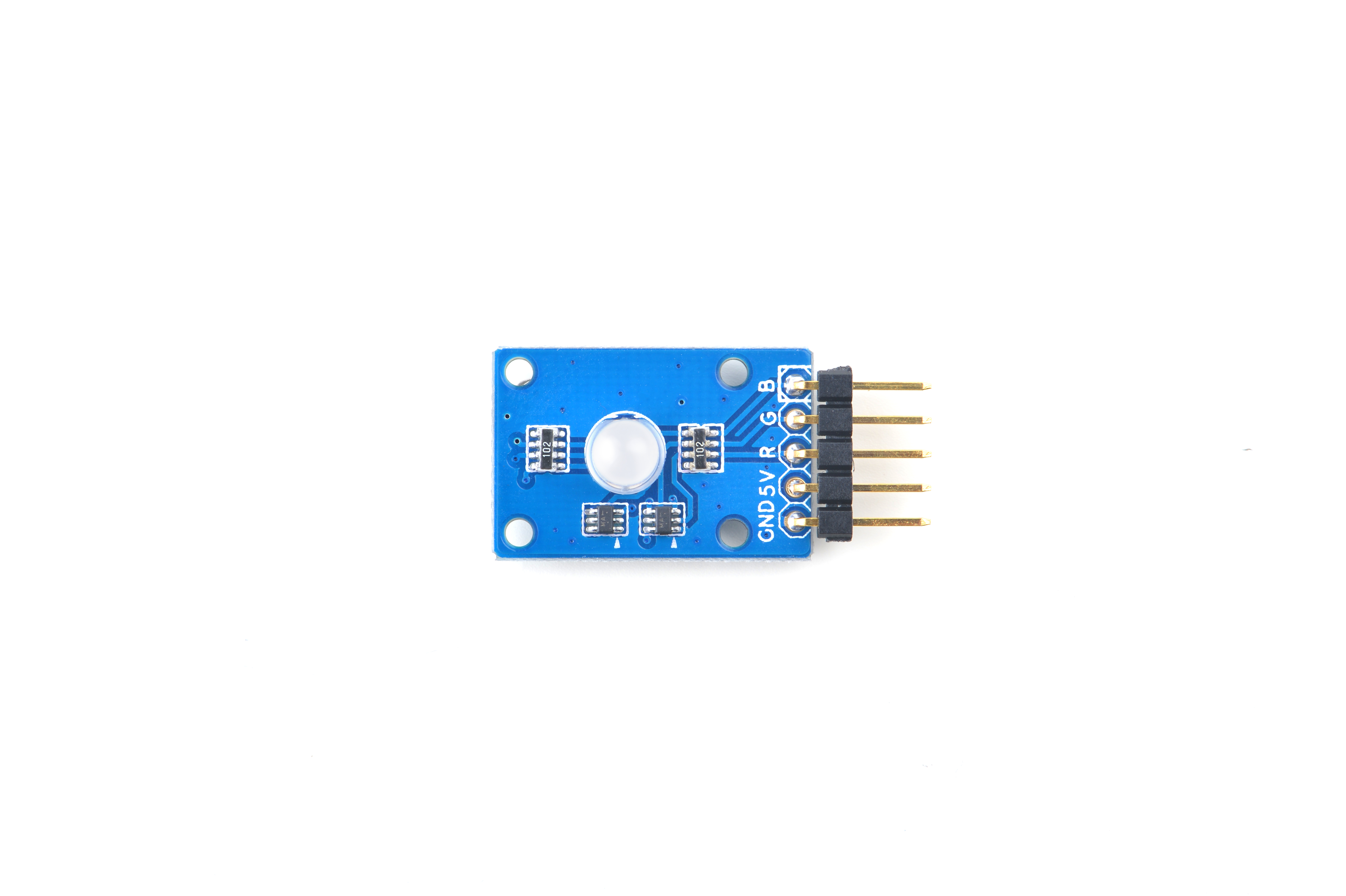
- Matrix-RGB_LED是一个RGB发光二极管模块。5-Pin 2.54mm排针,V接电源,G接地,R、G、B引脚分别控制二极管发出红、绿、蓝三种颜色的光,或者组合发出混色光。
- 您可以向R、G、B引脚输出静态的高低电平信号,也可以输出变化的PWM信号,信号电平可以是3.3V或5V。当您向R、G、B引脚输出高电平时LED以最大亮度发光,低电平就完全熄灭;向R、G、B引脚输出可变占空比的PWM信号可以调节R、G、B颜色光发光的亮度,从而形成多种颜色的混色光。
2 Features
- GPIO或PWM控制,3.3/5V电平,亮度通过PWM可调
- Small
- 2.54 mm pitch pin-header
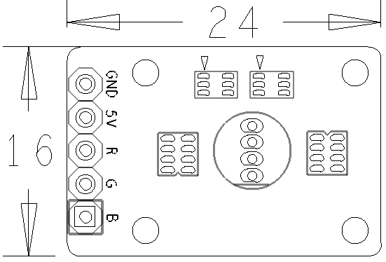
- PCB dimension(mm): 16 x 24
- Pin Description:
| Pin | Description |
| GND | Ground |
| 5V | Supply Voltage 5V |
| R | Red |
| G | Green |
| B | Blue |
3 工作原理
- RGB_LED的内部封装了三颗不同颜色的灯珠,三个灯珠的阳极或者阴极并联,当给另外三个引脚施加控制信号时,对应的LED就会亮起。当两种或三种LED亮起时,根据三原色原理,会组成其他颜色的光。施加PWM信号时,不同占空比的PWM信号可以调节R、G、B颜色光发光的亮度,从而组合成多种颜色。
4 Applications
4.1 Connect to NanoPi M1
Refer to the following connection diagram to connect the module to the NanoPi M1:
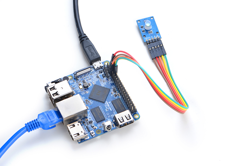
Connection Details:
| Matrix-RGBLED | NanoPi M1 |
| R | Pin7 |
| G | Pin8 |
| B | Pin10 |
| V | Pin4 |
| G | Pin6 |
4.2 Connect to NanoPi 2
Refer to the following connection diagram to connect the module to the NanoPi 2:
Connection Details:
| Matrix-RGBLED | NanoPi 2 |
| R | Pin7 |
| G | Pin8 |
| B | Pin10 |
| V | Pin4 |
| G | Pin6 |
4.3 Connect to NanoPi M2 / NanoPi 2 Fire
Refer to the following connection diagram to connect the module to the NanoPi M2/ NanoPi 2 Fire.
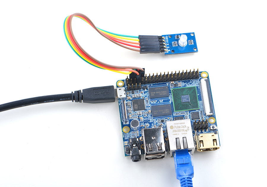
Connection Details:
| Matrix-RGBLED | NanoPi M2 |
| R | Pin7 |
| G | Pin8 |
| B | Pin10 |
| V | Pin4 |
| G | Pin6 |
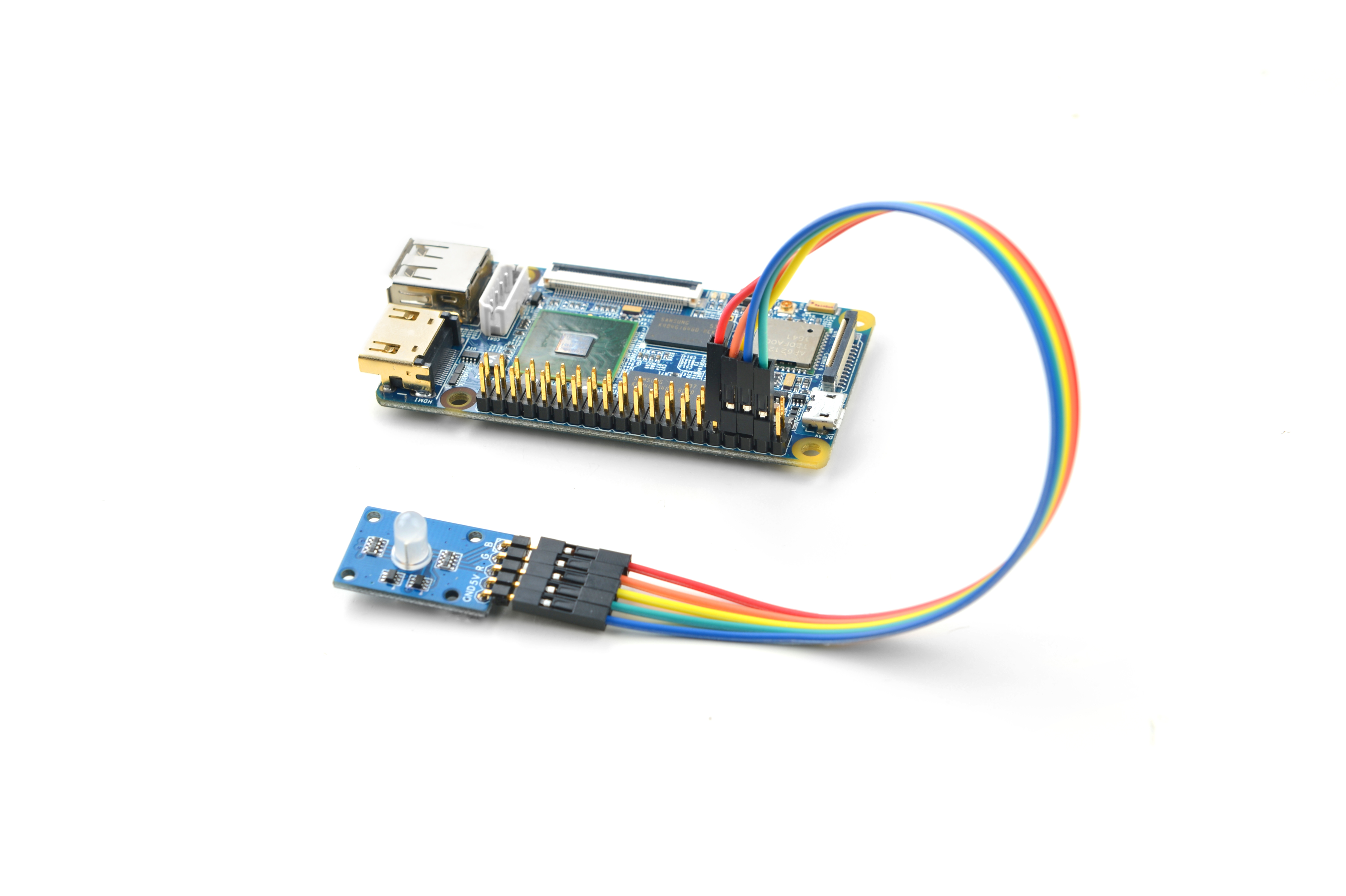
4.4 Connect to NanoPC-T2
Refer to the following connection diagram to connect the module to the NanoPC-T2:
Matrix-RGBLED_NanoPC-T2
Connection Details:
| Matrix-RGBLED | NanoPC-T2 |
| R | Pin15 |
| G | Pin16 |
| B | Pin17 |
| V | Pin29 |
| G | Pin30 |
5 编译运行测试程序
启动开发板并运行Debian系统,进入系统后克隆Matrix代码仓库:
$ apt-get update && apt-get install git
$ git clone https://github.com/friendlyarm/matrix.git
克隆完成后会得到一个名为matrix的目录。
编译并安装Matrix:
$ cd matrix
$ make && make install
运行测试程序:
$ matrix-rgb_led注意:此模块并不支持热插拔,启动系统前需要确保硬件连接正确。
运行效果如下:
Set RGB LED: 0
Set RGB LED: 1
Set RGB LED: 2
Set RGB LED: 3
Set RGB LED: 4
Set RGB LED: 5
Set RGB LED: 6
Set RGB LED: 7
可以看到RGBLED在不停地变换颜色。
6 代码说明
所有的开发板都共用一套Matrix代码,本模块的测试示例代码为matrix-rgb_led,内容如下:
int main(int argc, char ** argv)
{
    int ret = -1;
    int val, board;

    if ((board = boardInit()) < 0) {
        printf("Fail to init board\n");
        return -1;
    }
    if (board == BOARD_NANOPI_T2) {
        ledPin1 = GPIO_PIN(15);
        ledPin2 = GPIO_PIN(16);
        ledPin3 = GPIO_PIN(17);
    }
    if ((ret = exportGPIOPin(ledPin1)) == -1) {
        printf("exportGPIOPin(%d) failed\n", ledPin1);
    }
    if ((ret = setGPIODirection(ledPin1, GPIO_OUT)) == -1) {
        printf("setGPIODirection(%d) failed\n", ledPin1);
    }
    if ((ret = exportGPIOPin(ledPin2)) == -1) {
        printf("exportGPIOPin(%d) failed\n", ledPin2);
    }
    if ((ret = setGPIODirection(ledPin2, GPIO_OUT)) == -1) {
        printf("setGPIODirection(%d) failed\n", ledPin2);
    }
    if ((ret = exportGPIOPin(ledPin3)) == -1) {
        printf("exportGPIOPin(%d) failed\n", ledPin3);
    }
    if ((ret = setGPIODirection(ledPin3, GPIO_OUT)) == -1) {
        printf("setGPIODirection(%d) failed\n", ledPin3);
    }
    signal(SIGINT, intHandler);
    for (val = 0; val < 8; val++) {
        printf("Set RGB LED: %x\n", val);
        setRGBLED(val);
        usleep(1000 * 1000);
    }
    unexportGPIOPin(ledPin1);
    unexportGPIOPin(ledPin2);
    unexportGPIOPin(ledPin3);
    return 0;
}
API说明参考维基:Matrix API reference manual
