Difference between revisions of "NanoPi M1"
From FriendlyELEC WiKi
(→Layout) |
(→Layout) |
||
| Line 118: | Line 118: | ||
|11 || VSYNC || vertical synchronization to CPU from camera modules | |11 || VSYNC || vertical synchronization to CPU from camera modules | ||
|- | |- | ||
| − | |12 || HREF/HSYNC || | + | |12 || HREF/HSYNC || HREF/HSYNC signal to CPU from camera modules |
|- | |- | ||
| − | |14 || PCLK || | + | |14 || PCLK || PCLK signal to CPU from camera modules |
|- | |- | ||
| − | |16-23 || Data bit7-0 || | + | |16-23 || Data bit7-0 || data signals |
|} | |} | ||
| − | :''' | + | :'''Note:''' |
| − | ::#SYS_3.3V: 3. | + | ::#SYS_3.3V: 3.3V power output |
| − | ::#VDD_5V: | + | ::#VDD_5V: 5V power input/output. When the external device’s power is greater than the MicroUSB’s the external device is charging the board otherwise the board powers the external device. The input range is 4.7V ~ 5.6V |
| − | ::# | + | ::#All pins are 3.3V and output current is 5mA. It can drive small loads.可以带动小负荷模块,io都不能带负载 |
| − | ::# | + | ::#For more details please refer to the document: [http://wiki.friendlyarm.com/wiki/images/d/d8/NanoPi-M1-1603-Schematic.pdf NanoPi-M1-1603-Schematic.pdf] |
===Board Dimension=== | ===Board Dimension=== | ||
Revision as of 10:54, 14 March 2016
Contents
1 介绍
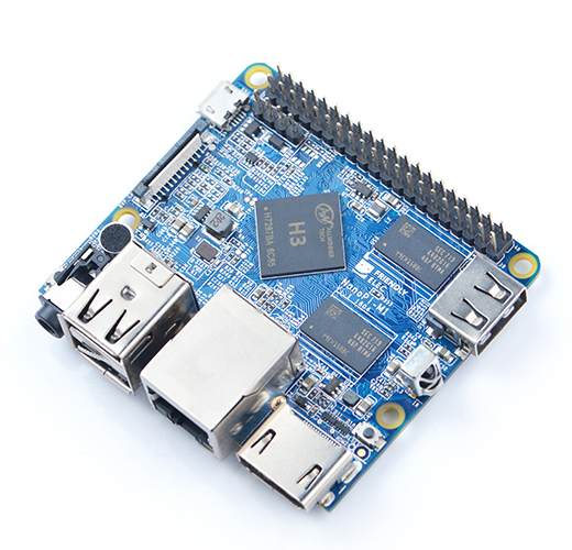
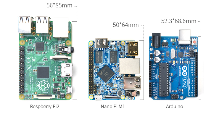
- NanoPi M1(以下简称M1)是友善之臂团队面向创客、嵌入式爱好者,电子艺术家、发烧友等群体推出的又一款完全开源的掌上创客神器,它的大小只有树莓派的大约2/3,可运行Ubuntu MATE、Debian、Android等操作系统。
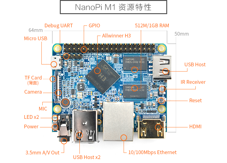
- NanoPi M1采用了全志高性能处理器Allwinner H3,集成以太网、红外接收、视频/音频输出等接口,支持HDMI、AVOUT视频输出等功能。
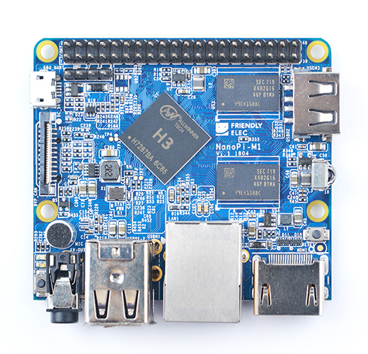
- 尽管体积很小,设计却紧凑美观。NanoPi M1引出了相当丰富的接口,包括HDMI、以太网、USB-Host、USB-OTG、DVP camera和AVOUT(音频+视频)等。而且集成了板载麦克风,红外接收器,并且兼容树莓派GPIO口,并且拥有独立的调试串口等。
2 Features
- CPU: Allwinner H3, Quad-core Cortex-A7@1.2GHz
- GPU: Mali400MP2@600MHz,Supports OpenGL ES2.0
- DDR3 RAM: 512MB
- Connectivity: 10/100M Ethernet
- Audio: 3.5mm audio jack/Via HDMI
- Microphone: Onboard microphone
- IR Receiver: Onboard IR receiver
- USB Host:Type A, USB 2.0 x 3
- MicroSD Slot x 1
- MicroUSB: for data transmission and power input, OTG
- Video Output: HDMI 1.4 1080P, CVBS
- DVP Camera Interface: 24pin, 0.5mm pitch FPC seat
- Debug Serial Port: 4Pin, 2.54mm pitch pin header
- GPIO: 2.54mm spacing 40pin, compatible with Raspberry Pi's GPIO. It includes UART, SPI, I2C, IO etc
- User Key: Power LED x 1, Reset x 1
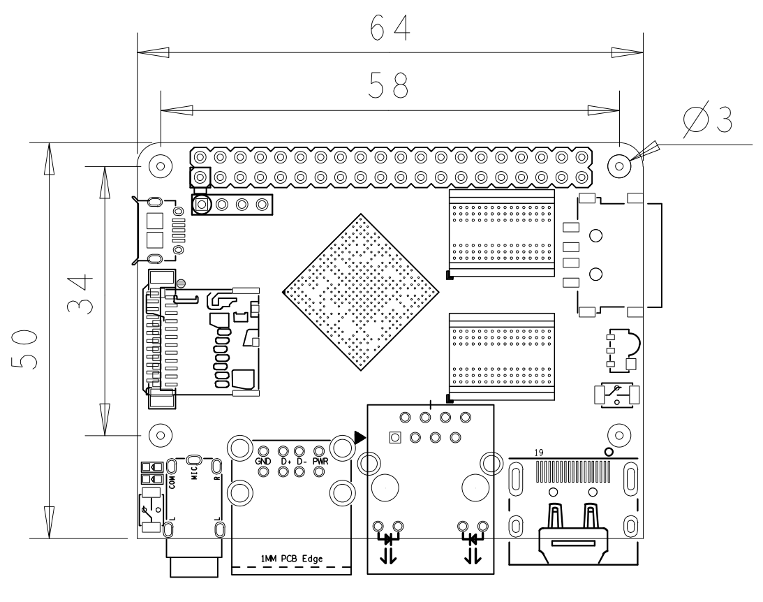
- PC Size: 64 x 50mm
- Power Supply: DC 5V/2A
- OS/Software: u-boot,Ubuntu MATE,Debian
3 Diagram, Layout and Dimension
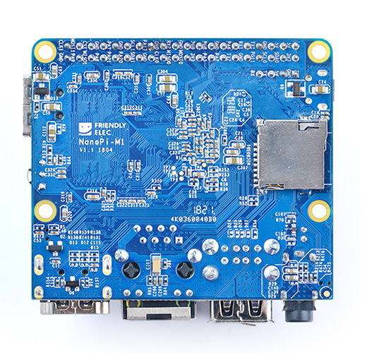
3.1 Layout
- GPIO Pin Spec
Pin# Name Pin# Name 1 SYS_3.3V 2 VDD_5V 3 I2C0_SDA 4 VDD_5V 5 I2C0_SCL 6 GND 7 GPIOG11 8 UART1_TX/GPIOG6 9 GND 10 UART1_RX/GPIOG7 11 UART2_TX/GPIOA0 12 PWM1/GPIOA6 13 UART2_RTS/GPIOA2 14 GND 15 UART2_CTS/GPIOA3 16 UART1_RTS/GPIOG8 17 SYS_3.3V 18 UART1_CTS/GPIOG9 19 SPI0_MOSI/GPIOC0 20 GND 21 SIP0_MISO/GPIOC1 22 UART2_RX/GPIOA1 23 SPI0_CLK/GPIOC29 24 SPI0_CS/GPIOC3 25 GND 26 SPDIF-OUT/GPIOA17 27 I2C1_SDA/GPIOA19 28 I2C1_SCL/GPIOA18 29 GPIOA20 30 GND 31 GGPIOA21 32 GPIOA7 33 GPIOA8 34 GND 35 UART3_CTS/SPI1_MISO/GPIOA16 36 UART3_TX/SPI1_CS/GPIOA13 37 GPIOA9 38 UART3_RTS/SPI1_MOSI/GPIOA15 39 GND 40 UART3_RX/SPI1_CLK/GPIOA14
- Debug Port(UART0)
Pin# Name 1 GND 2 VDD_5V 3 UART_TXD0 4 UART_RXD0
- DVP Camera IF Pin Spec
Pin# Name Description 1, 2 SYS_3.3V 3.3V power output, to camera modules 7,9,13,15,24 GND Gound, 0V 3 I2C2_SCL I2C Clock Signal 4 I2C2_SDA I2C Data Signal 5 GPIOE15 Regular GPIO, control signals output to camera modules 6 GPIOE14 Regular GPIO, control signals output to camera modules 8 MCLK Clock signals output to camera modules 10 NC Not Connected 11 VSYNC vertical synchronization to CPU from camera modules 12 HREF/HSYNC HREF/HSYNC signal to CPU from camera modules 14 PCLK PCLK signal to CPU from camera modules 16-23 Data bit7-0 data signals
- Note:
- SYS_3.3V: 3.3V power output
- VDD_5V: 5V power input/output. When the external device’s power is greater than the MicroUSB’s the external device is charging the board otherwise the board powers the external device. The input range is 4.7V ~ 5.6V
- All pins are 3.3V and output current is 5mA. It can drive small loads.可以带动小负荷模块,io都不能带负载
- For more details please refer to the document: NanoPi-M1-1603-Schematic.pdf
3.2 Board Dimension
- For more details please refer to: pcb file in dxf
4 快速入门
4.1 准备工作
5 Resources
- Schematic NanoPi-M1-1603-Schematic.pdf
- Dimensional Diagram pcb file in dxf
