Difference between revisions of "All-in-One Android Touch Screen/zh"
From FriendlyELEC WiKi
(→支持的开发板) |
(→支持的开发板) |
||
| Line 147: | Line 147: | ||
==支持的开发板== | ==支持的开发板== | ||
| − | + | [http://wiki.friendlyarm.com/wiki/index.php/Smart4418/zh Smart4418] | |
| − | + | [http://wiki.friendlyarm.com/wiki/index.php/Smart6818/zh Smart6818] | |
| − | + | ||
| − | + | ||
| − | + | ||
Revision as of 08:12, 15 March 2019
1 介绍
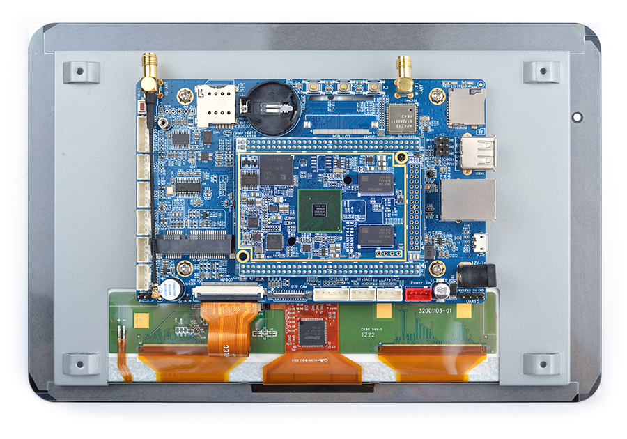
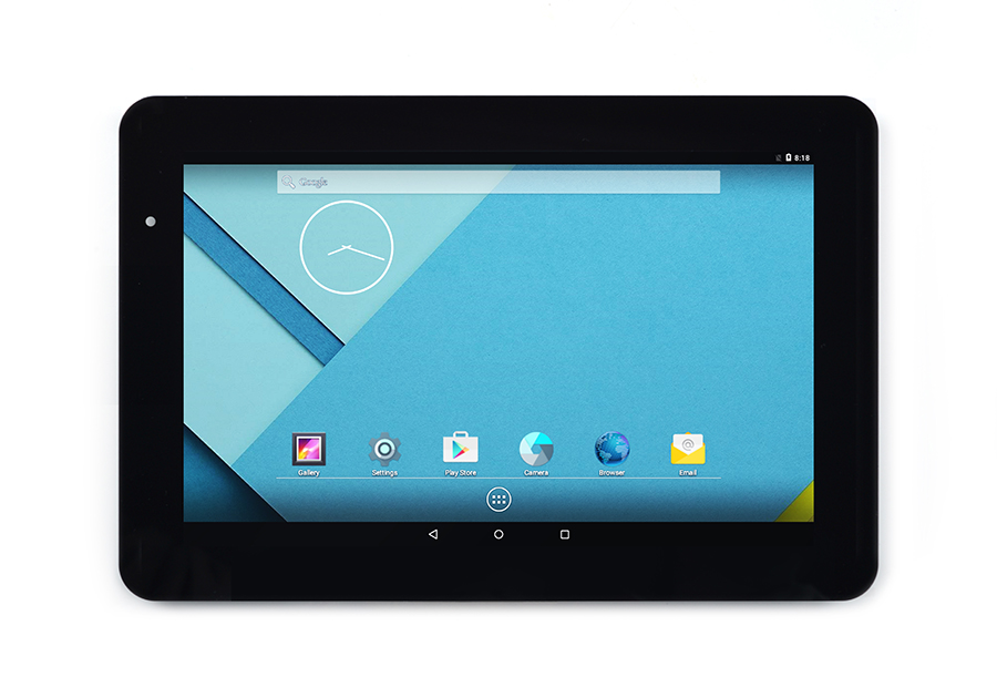
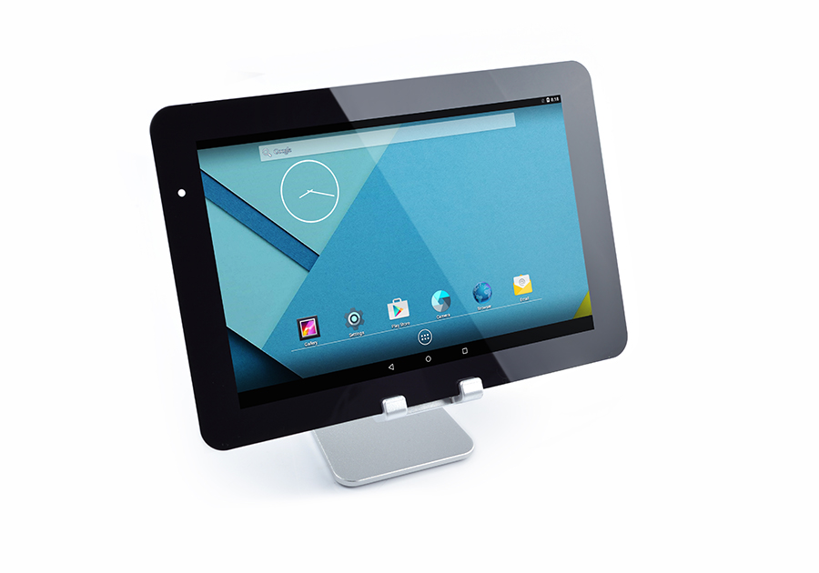
- All-in-One Android Touch Screen是友善电子设计开发并生产的一款9寸高清电容触摸显示屏,分辨率为1280 x 800,支持触摸,背光可调(通过i2c通讯),特意定做的底板接口适用于友善电子出品的Smart4418、Smart6818核心板,可支持Linux, Android等嵌入式系统,并且驱动开源。
- 底板使用定制的支架和屏幕固定,没有制作外壳,非常方便企业用户安装到设备中做二次开始使用。
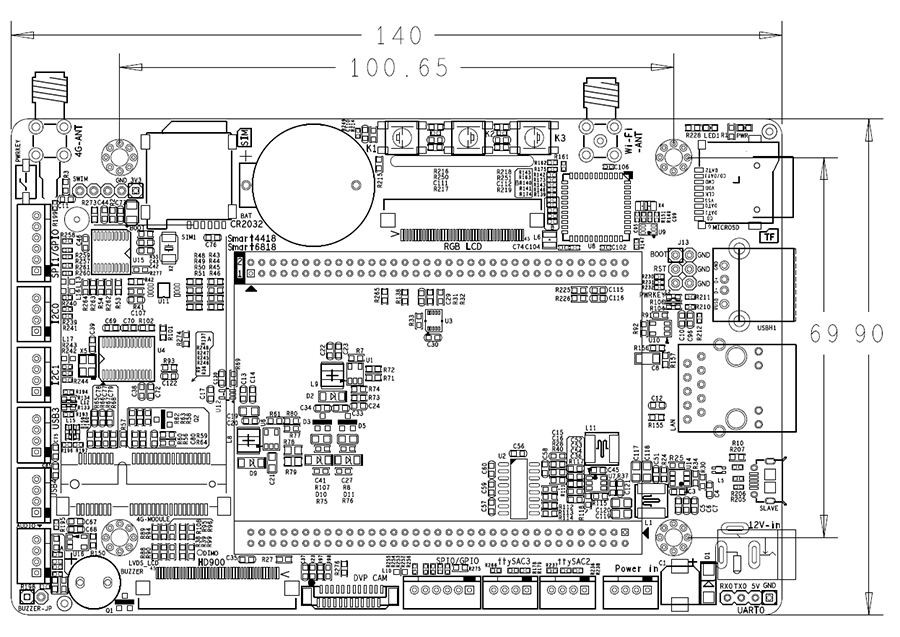
2 机械尺寸图
3 接口定义
- HD900(LVDS)接口定义
Pin# Symbol I/O Function 1 VDD-C-TP P Power supply input for C-TP 2 GND-C-TP P Ground for C-TP 3 RST-C-TP I Reset C-TP 4 SCL I I2C Clock 5 SDA I/O I2C Data 6 INT O Interrupt pin 7 GND P Ground 8 GND P Ground 9 GND P Ground 10 VCOM P Common Voltage 11 VDD P Power Voltage for digital circuit 12 VDD P Power Voltage for digital circuit 13 RST GLOBAL I Global reset pin 14 STBYB I Standby mode 15 GND P Ground 16 RXIN0- I -LVDS differential data input 17 RXIN0+ I +LVDS differential data input 18 GND P Ground 19 RXIN1- I -LVDS differential data input 20 RXIN1+ I +LVDS differential data input 21 GND P Ground 22 RXIN2- I -LVDS differential data input 23 RXIN2+ I +LVDS differential data input 24 GND P Ground 25 RXCLKIN- I -LVDS differential clock input 26 RXCLKIN+ I +LVDS differential clock input 27 GND P Ground 28 RXIN3- I -LVDS differential data input 29 RXIN3+ I +LVDS differential data input 30 GND P Ground 31 GND P Ground 32 DIMO O Backlight CABC controller signal output 33 SELB I 6/8bit mode select 34 AVDD P Power for Analog Circuit 35 GND P Ground 36 LED- P LED Cathode 37 LED- P LED Cathode 38 L/R I Horiaontal inversion 39 U/D I Vertiacl inversion 40 VGL P Gate OFF Voltage 41 CABCEN1 I CABC H/W enable 42 CANCEN0 I CABC H/W enable 43 VGH P Gate ON Voltage 44 LED+ P LED Anode 45 LED+ P LED Anode
- DVP CAM 接口定义
Pin# Name Function 1, 2 SYS_3.3V 3.3V power output, to camera modules 7,9,13,15,24 GND Gound, 0V 3 I2C2_SCL I2C Clock Signal 4 I2C2_SDA I2C Data Signal 5 GPIOE15 Regular GPIO, control signals output to camera modules 6 GPIOE14 Regular GPIO, control signals output to camera modules 8 MCLK Clock signals output to camera modules 10 NC Not Connected 11 VSYNC vertical synchronization to CPU from camera modules 12 HREF/HSYNC HREF/HSYNC signal to CPU from camera modules 14 PCLK PCLK signal to CPU from camera modules 16-23 Data bit7-0 data signals
4 连接使用
5 Datasheet下载
- [点击下载]
6 原理图下载
- [点击下载]


