Difference between revisions of "NanoPi Duo2 IoT-Box"
From FriendlyELEC WiKi
(→Introduction) |
(→Introduction) |
||
| Line 8: | Line 8: | ||
*It has an onboard quad-band GSM/GPRS module SIM800C. | *It has an onboard quad-band GSM/GPRS module SIM800C. | ||
*It has 2.0mm I2C interface, UART interface, audio interface and CVBS interface etc and can work with various external modules. | *It has 2.0mm I2C interface, UART interface, audio interface and CVBS interface etc and can work with various external modules. | ||
| − | * | + | *Its MicroUSB port is only used as power output. And a power switch is added too. |
| − | * | + | *It has one power LED and one GPIO accessed LED. |
| − | * | + | *It populates the two USB ports of the NanoPi Duo2. |
| − | * | + | *It populates the serial ports and Ethernet port of the NanoPi Duo2. |
| − | * | + | *It has an IPX to SMA antenna connector for WiFi antennas. |
==特性== | ==特性== | ||
Revision as of 09:38, 11 October 2018
Contents
1 Introduction
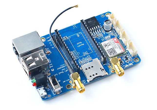
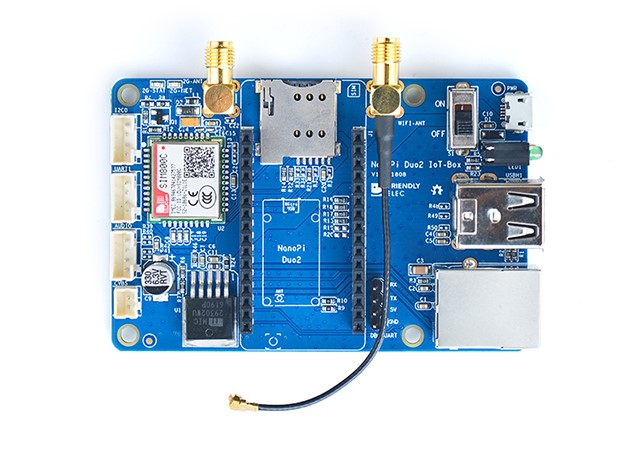
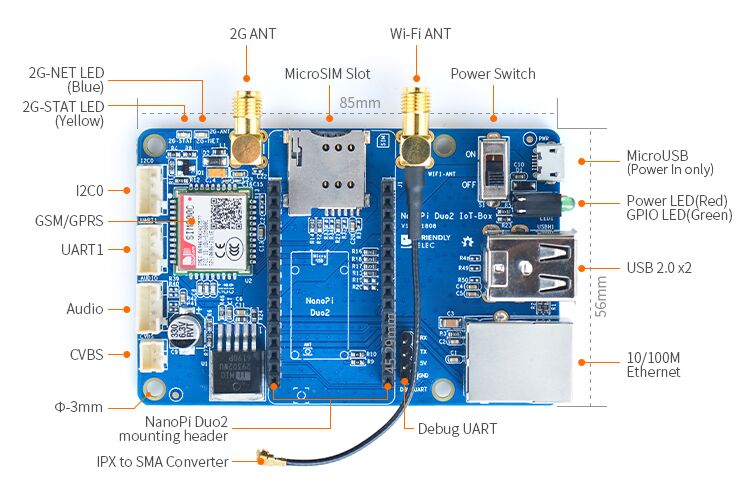
- The NanoPi Duo2 IoT-Box is a dedicated carrier board for the NanoPi Duo2. It populates Ethernet port, serial port, audio and USB etc.
- It has an onboard quad-band GSM/GPRS module SIM800C.
- It has 2.0mm I2C interface, UART interface, audio interface and CVBS interface etc and can work with various external modules.
- Its MicroUSB port is only used as power output. And a power switch is added too.
- It has one power LED and one GPIO accessed LED.
- It populates the two USB ports of the NanoPi Duo2.
- It populates the serial ports and Ethernet port of the NanoPi Duo2.
- It has an IPX to SMA antenna connector for WiFi antennas.
2 特性
- 板载四频GSM/GPRS模块
- 2个USB Host接口
- 扩展的调试串口和网络接口
- 音频输入、输出接口
- MicroUSB电源输入,并添加了电源开关
- IPX转SMA WiFi天线转接线
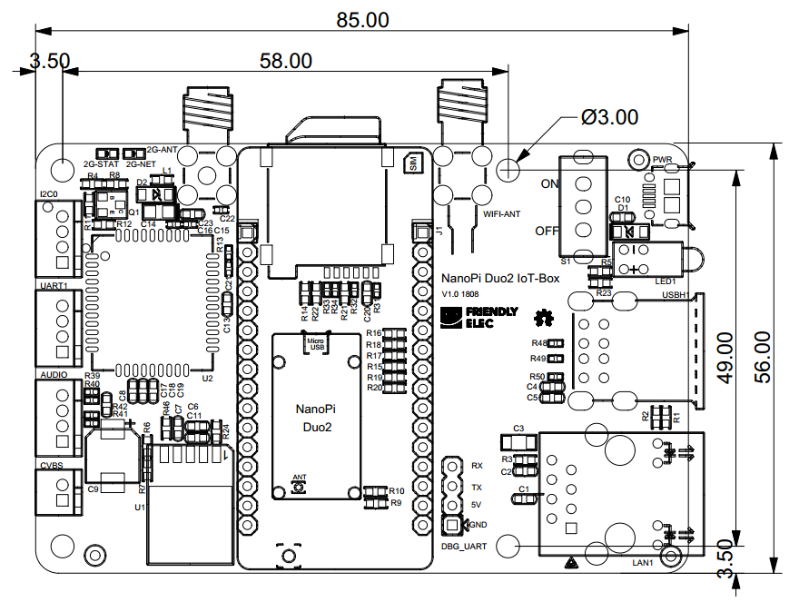
- PCB尺寸(mm):85x56
2.1 接口说明
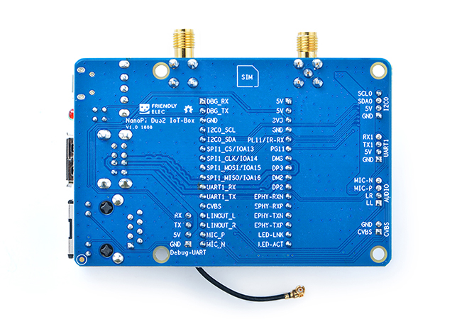
NanoPi Duo2 IoT-Box接口如右图所示,接口引脚丝印都在板子背面做了详细标注。
- NanoPi Duo header引脚定义
Number# Name Number# Name 1 VDD_5V 17 DEBUG_RX(UART_RXD0)/GPIOA5/PWM0 2 VDD_5V 18 DEBUG_TX(UART_TXD0)/GPIOA4 3 SYS_3.3V 19 GND 4 GND 20 I2C0_SCL/GPIOA11 5 GPIOL11/IR-RX 21 I2C0_SDA/GPIOA12 6 GPIOG11 22 UART3_TX/SPI1_CS/GPIOA13 7 USB-DM3 23 UART3_RX/SPI1_CLK/GPIOA14 8 USB-DP3 24 UART3_CTS/SPI1_MISO/GPIOA16 9 USB-DM2 25 UART3_RTS/SPI1_MOSI/GPIOA15 10 USB-DP2 26 UART1_RX/GPIOG7 11 EPHY-RXN 27 UART1_TX/GPIOG6 12 EPHY-RXP 28 CVBS 13 EPHY-TXN 29 LINEOUT_L 14 EPHY-TXP 30 LINEOUT_R 15 EPHY-LED-LINK 31 MIC_P 16 EPHY-LED-SPD 32 MIC_N
3 硬件连接
NanoPi Duo2可直接装配在NanoPi Duo2 IoT-Box底板上,装配时注意NanoPi Duo2的方向,参考下图连接模块:
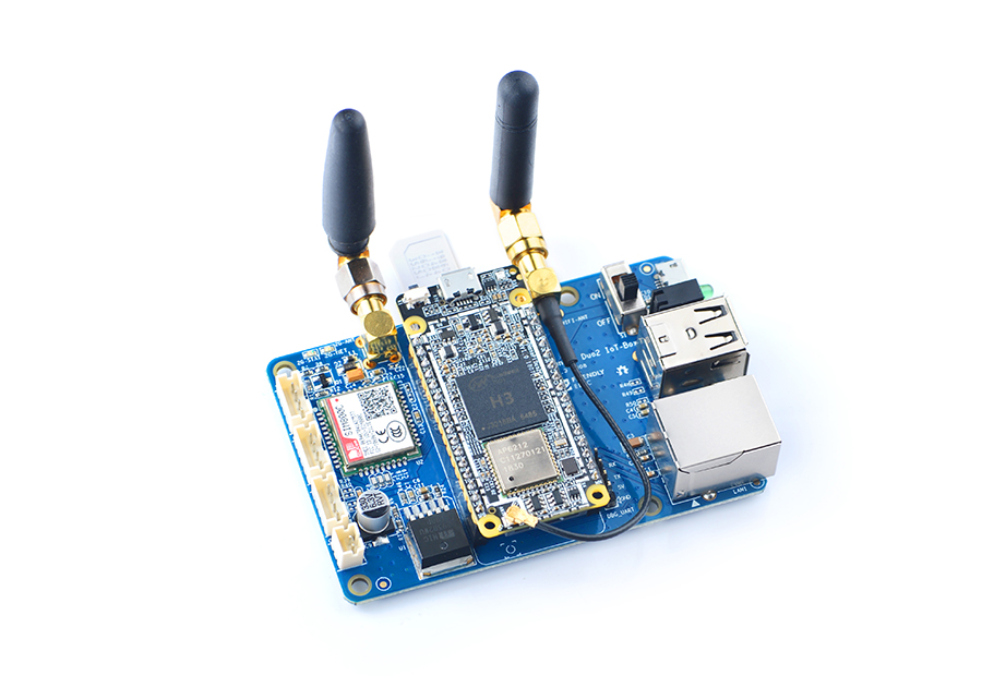
使用NanoPi Duo2 IoT-Box底板,能方便的使用有线网络、USB等接口
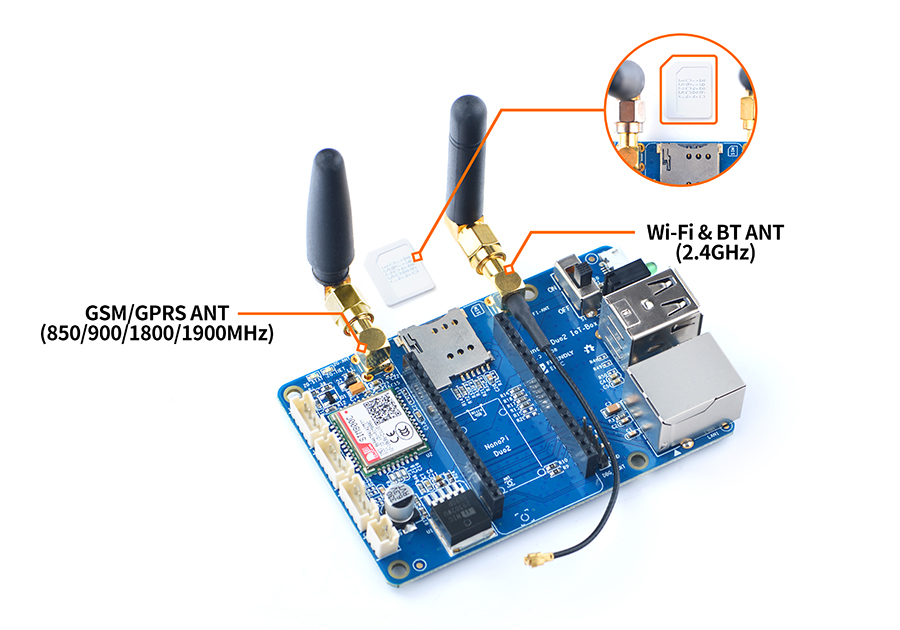
NanoPi Duo2 IoT-Box底板使用的GSM/GPRS天线和WiFi天线的频段不一样,请注意区分,参考下图装配:
4 软件使用
4.1 1、GSM/GPRS模块的使用
使用前请先插入可以使用的SIM卡,并装配GSM/GPRS天线:
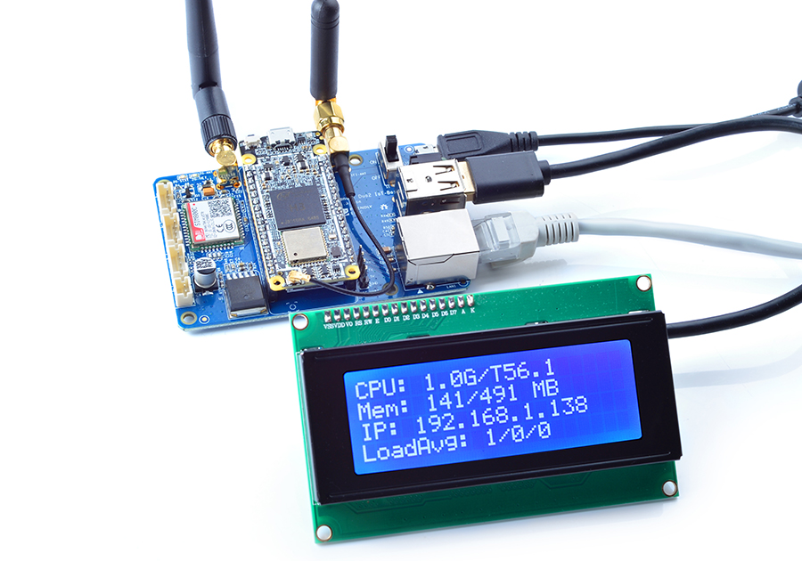
4.2 2、USB Host接口的使用
NanoPi Duo2 IoT-Box的USB Host接口可以方便的外接常用的USB设备,连接Matrix - LCD2USB如下所示:
连接Matrix - LCD2USB
4.3 3、音频输入与输出
1、可使用以下命令录音:
arecord -D hw:0,0 -f cd test.wav
运行效果如下:
![]()
2、可使用以下命令播放音频文件,例如播放/root/Music/test.wav
aplay /root/Music/test.wav
运行效果如下:

可以使用alsamixer工具调节播放音乐的音量
5 相关资料
- [Schematic](Schematic_NanoPi Duo2 IoT-Box.pdf)
- [Dimension](Dimension_NanoPi Duo2 IoT-Box(dxf))
- [Manual](SIM800_Series_AT_Command_Manual_V1.10.pdf)
