Difference between revisions of "NanoPi M1 Plus"
(Created page with "查看中文") |
|||
| Line 1: | Line 1: | ||
[[NanoPi M1 Plus/zh|查看中文]] | [[NanoPi M1 Plus/zh|查看中文]] | ||
| + | |||
| + | ==Introduction== | ||
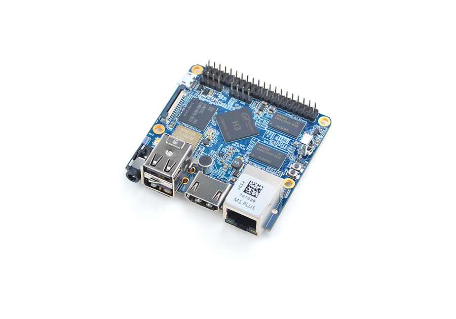
| + | [[File:NanoPi M1 Plus-1.jpg|thumb|frameless|300px|Overview]] | ||
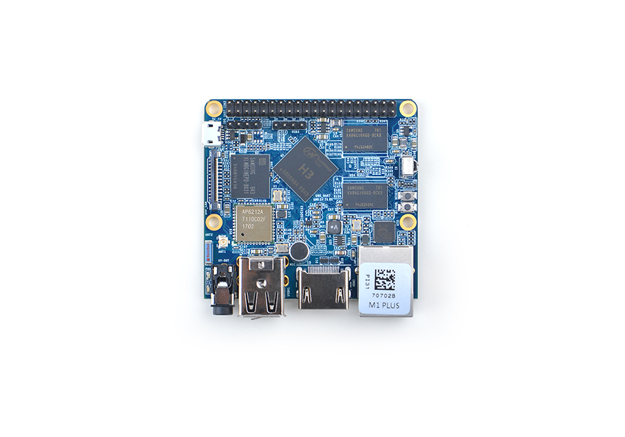
| + | [[File:NanoPi M1 Plus-2.jpg|thumb|frameless|300px|Front]] | ||
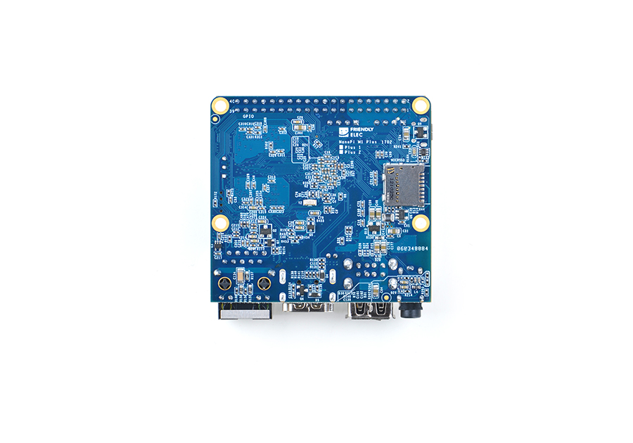
| + | [[File:NanoPi M1 Plus-3.jpg|thumb|frameless|300px|Back]] | ||
| + | [[File:NanoPi M1 Plus-4.jpg|thumb|frameless|300px|3D Housing]] | ||
| + | * The NanoPi M1 Plus is designed and developed by FriendlyElec for professionals, enterprise users, makers and hobbyists. It is only two thirds the size of a Raspberry Pi. FriendlyElec has made a Debian, Ubuntu-MATE, Ubuntu-Core and Android images ready for it. | ||
| + | * The NanoPi M1 Plus uses the Allwinner H3 Soc. It integrates Gbps Ethernet, IR receiver, video/audio output, WiFi & Bluetooth, onboard microphone and supports DVP/Camera/HDMI and CVBS. It has a serial debug port. Its GPIO pins are compatible with those of a Raspberry Pi. | ||
| + | ==Hardware Spec== | ||
| + | * CPU: Allwinner H3, Quad-core Cortex-A7@1.2GHz | ||
| + | * GPU: Mali400MP2@600MHz,Supports OpenGL ES2.0 | ||
| + | * DDR3 RAM: 1GB | ||
| + | * eMMC: 8GB | ||
| + | * Wireless: 802.11 b/g/n | ||
| + | * Bluetooth: 4.0 dual mode | ||
| + | * Antenna Interface: Shared by WiFi and Bluetooth, IPX interface | ||
| + | * Connectivity: 10/100/1000M Ethernet | ||
| + | * Audio: 3.5mm jack/Via HDMI | ||
| + | * Microphone: onboard microphone | ||
| + | * IR: onboard IR receiver | ||
| + | * USB Host: USB 2.0 x 3, 2 x USB Type A and 1 x 2.54mm pitch pin-header | ||
| + | * MicroSD Slot: x1 | ||
| + | * MicroUSB: power input and data transmission, OTG | ||
| + | * Audio Output: HDMI 1.4 1080P, CVBS | ||
| + | * DVP Camera Interface: 24pin, 0.5mm pitch FPC seat | ||
| + | * Serial Debug Port: 4Pin, 2.54mm pitch pin-header | ||
| + | * GPIO: 40pin, 2.54mm pitch pin-header, compatible with RasberryPi 2's GPIO. It contains UART, SPI, I2C, I2S/PCM, SPDIF-OUT and IO | ||
| + | * User Button: 1 x Power Button and 1 x Reset Button | ||
| + | * LED: 1 x Power LED and 1 x System Status LED | ||
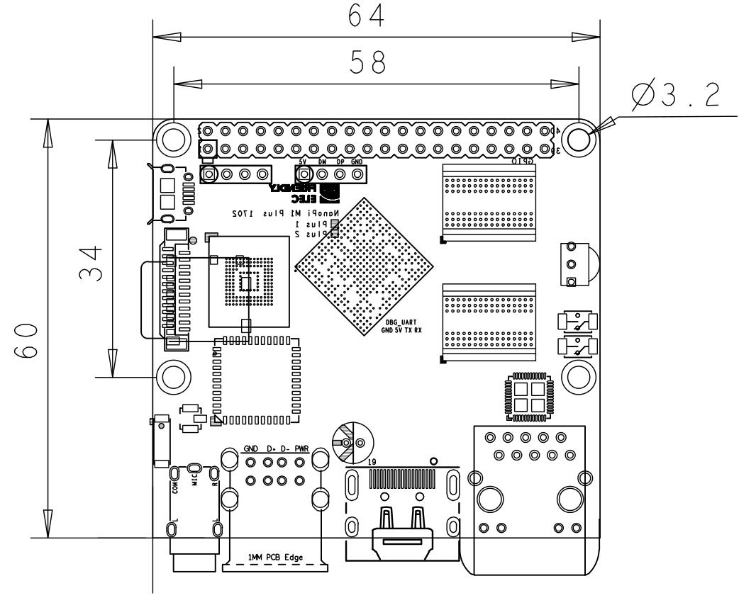
| + | * PCB Dimension: 64 x 60 mm, ENIG | ||
| + | * Power Supply: DC 5V/2A | ||
| + | * OS/Software: u-boot, Debian, Ubuntu-MATE, Ubuntu-Core | ||
| + | |||
| + | ==Diagram, Layout and Dimension== | ||
| + | ===Layout=== | ||
| + | [[File:-1602-if01.png |thumb|300px|NanoPi M1 Plus Layout]] | ||
| + | |||
| + | * '''GPIO Pin Description''' | ||
| + | ::{| class="wikitable" | ||
| + | |- | ||
| + | |Pin# || Name || Linux gpio ||Pin# || Name || Linux gpio | ||
| + | |- | ||
| + | |1 || SYS_3.3V || ||2 || VDD_5V || | ||
| + | |- | ||
| + | |3 || I2C0_SDA || ||4 || VDD_5V || | ||
| + | |- | ||
| + | |5 || I2C0_SCL || ||6 || GND || | ||
| + | |- | ||
| + | |7 || GPIOG11 || 203 ||8 || UART1_TX/GPIOG6 || 198 | ||
| + | |- | ||
| + | |9 || GND || ||10 || UART1_RX/GPIOG7 || 199 | ||
| + | |- | ||
| + | |11 || UART2_TX/GPIOA0 || 0 ||12 || PWM1/GPIOA6 || 6 | ||
| + | |- | ||
| + | |13 || UART2_RTS/GPIOA2 || 2 ||14 || GND || | ||
| + | |- | ||
| + | |15 || UART2_CTS/GPIOA3 || 3 ||16 || UART1_RTS/GPIOG8 || 200 | ||
| + | |- | ||
| + | |17 || SYS_3.3V || ||18 || UART1_CTS/GPIOG9 || 201 | ||
| + | |- | ||
| + | |19 || SPI0_MOSI/GPIOC0 || 64 ||20 || GND || | ||
| + | |- | ||
| + | |21 || SPI0_MISO/GPIOC1 || 65 ||22 || UART2_RX/GPIOA1 || 1 | ||
| + | |- | ||
| + | |23 || SPI0_CLK/GPIOC2 || 66 ||24 || SPI0_CS/GPIOC3 || 67 | ||
| + | |- | ||
| + | |25 || GND || ||26 || SPDIF-OUT/GPIOA17 || 17 | ||
| + | |- | ||
| + | |27 || I2C1_SDA/GPIOA19/PCM0_CLK/I2S0_BCK || 19 ||28 || I2C1_SCL/GPIOA18/PCM0_SYNC/I2S0_LRCK || 18 | ||
| + | |- | ||
| + | |29 || GPIOA20/PCM0_DOUT/I2S0_SDOUT || 20 ||30 || GND || | ||
| + | |- | ||
| + | |31 || GPIOA21/PCM0_DIN/I2S0_SDIN || 21 ||32 || NC || | ||
| + | |- | ||
| + | |33 || NC || ||34 || GND || | ||
| + | |- | ||
| + | |35 || NC || ||36 || NC || | ||
| + | |- | ||
| + | |37 || GPIOA9 || 9 ||38 || NC || | ||
| + | |- | ||
| + | |39 || GND || ||40 || NC || | ||
| + | |} | ||
| + | |||
| + | * '''Debug Port(UART0)''' | ||
| + | ::{| class="wikitable" | ||
| + | |- | ||
| + | |Pin# || Name | ||
| + | |- | ||
| + | |1 || GND | ||
| + | |- | ||
| + | |2 || VDD_5V | ||
| + | |- | ||
| + | |3 || UART_TXD0 | ||
| + | |- | ||
| + | |4 || UART_RXD0 | ||
| + | |} | ||
| + | |||
| + | * '''USB Pin Header''' | ||
| + | ::{| class="wikitable" | ||
| + | |- | ||
| + | |Pin# || Name | ||
| + | |- | ||
| + | |1 || 5V | ||
| + | |- | ||
| + | |2 || DM | ||
| + | |- | ||
| + | |3 || DP | ||
| + | |- | ||
| + | |4 || GND | ||
| + | |} | ||
| + | |||
| + | * '''DVP Camera Interface Pin Description''' | ||
| + | ::{| class="wikitable" | ||
| + | |- | ||
| + | |Pin# || Name || Description | ||
| + | |- | ||
| + | |1, 2 || SYS_3.3V || 3.3V Output, it can be used to power camera modules | ||
| + | |- | ||
| + | |7,9,13,15,24 || GND || Ground, 0V | ||
| + | |- | ||
| + | |3 || I2C2_SCL || I2C clock signal | ||
| + | |- | ||
| + | |4 || I2C2_SDA || I2C data signal | ||
| + | |- | ||
| + | |5 || GPIOE15 || regular GPIO, used to control connected camera modules | ||
| + | |- | ||
| + | |6 || GPIOE14 || regular GPIO, used to control connected camera modules | ||
| + | |- | ||
| + | |8 || MCLK || 提供给外部摄像头模块的时钟信号 | ||
| + | |- | ||
| + | |10 || NC || Not connected | ||
| + | |- | ||
| + | |11 || VSYNC || vertical synchronization | ||
| + | |- | ||
| + | |12 || HREF/HSYNC || horizontal synchronization | ||
| + | |- | ||
| + | |14 || PCLK || 外部摄像头模块输出给CPU的像数点信号 | ||
| + | |- | ||
| + | |16-23 || Data bit7-0 || data bits | ||
| + | |} | ||
| + | :'''Notes''' | ||
| + | ::#SYS_3.3V: 3.3V power output | ||
| + | ::#VDD_5V: 5V power output5V. When the external device’s power is greater than the MicroUSB’s the external device is charging the board otherwise the board powers the external device.The input range is 4.7V ~ 5.6V | ||
| + | ::#All pins are 3.3V, output current is 5mA | ||
| + | ::#For more details refer to the document:[http://wiki.friendlyarm.com/wiki/images/8/85/NanoPi-M1-Plus-1702-Schematic.pdf NanoPi-M1-Plus-1702-Schematic.pdf] | ||
| + | |||
| + | ===Board Dimension=== | ||
| + | [[File:NanoPi-M1-Plus-1702-Drawing.jpg|frameless|500px|]] | ||
| + | |||
| + | ::For more details please refer to the document:[http://wiki.friendlyarm.com/wiki/images/a/a9/NanoPi-M1-Plus-1702-Drawing%28dxf%29.zip pcb in dxf format] | ||
| + | |||
| + | ==Get Started== | ||
| + | ===Essentials You Need=== | ||
| + | Before starting to use your NanoPi M1 Plus get the following items ready | ||
| + | * NanoPi M1 Plus | ||
| + | * MicroSD Card/TF Card: Class 10 or Above, minimum 8GB SDHC | ||
| + | * A DC 5V/2A power is a must | ||
| + | * HDMI monitor | ||
| + | * USB keyboard, mouse and possible a USB hub(or a TTL to serial board) | ||
| + | * A host computer running Ubuntu 14.04 64 bit system | ||
| + | |||
| + | ===经测试使用的TF卡=== | ||
| + | 制作启动的TF卡时,建议Class10或以上的 8GB SDHC卡。以下是经友善之臂测试验证过的高速TF卡: | ||
| + | *SanDisk闪迪 TF 8G Class10 Micro/SD 高速 TF卡: | ||
| + | [[File:SanDisk MicroSD.png|frameless|100px|SanDisk MicroSD 8G]] | ||
| + | *SanDisk闪迪 TF128G 至尊高速MicroSDXC TF 128G Class10 48MB/S: | ||
| + | [[File:SanDisk MicroSD-01.png|frameless|100px|SanDisk MicroSD 128G]] | ||
| + | *川宇 8G手机内存卡 8GTF卡存储卡 C10高速class10 micro SD卡: | ||
| + | [[File:SanDisk MicroSD-02.png|frameless|100px|chuanyu MicroSD 8G]] | ||
| + | |||
| + | ===制作一张带运行系统的TF卡=== | ||
| + | ====下载系统固件==== | ||
| + | 访问[https://pan.baidu.com/s/1boNTLKF 下载地址]下载需要的固件文件(officail-ROMs目录)和烧写工具(tools目录):<br /> | ||
| + | |||
| + | ::{| class="wikitable" | ||
| + | |- | ||
| + | |colspan=2|使用以下固件: | ||
| + | |- | ||
| + | |nanopi-m1-plus-debian-sd4g.img.zip || Debian系统固件 | ||
| + | |- | ||
| + | |nanopi-m1-plus-ubuntu-core-qte-sd4g.img.zip || 小型的Ubuntu core系统,内含Qt Embedded图形库 | ||
| + | |- | ||
| + | |nanopi-m1-eflasher-sd8g.img.zip || 基于Ubuntu core系统,具有烧写系统到eMMC | ||
| + | 的功能 | ||
| + | |- | ||
| + | |nanopi-m1-plus-android.img.zip || Android系统固件 | ||
| + | |- | ||
| + | |colspan=2|烧写工具: | ||
| + | |- | ||
| + | |win32diskimager.rar || Windows平台下的Debian系统烧写工具,Linux平台下可以用dd命令烧写Debian系统 | ||
| + | |- | ||
| + | |PhoenixCard_V310.rar || Windows平台下的Android系统烧写工具,注意:Android系统固件禁止在Linux平台下用dd命令烧写 | ||
| + | |- | ||
| + | |HDDLLF.4.40.exe || Windows平台下用于格式化TF卡的工具 | ||
| + | |- | ||
| + | |} | ||
| + | |||
| + | ====TF卡启动系统==== | ||
| + | =====制作Debian系统TF卡===== | ||
| + | *将固件nanopi-m1-plus-debian-sd4g.img.zip和烧写工具win32diskimager.rar分别解压,在Windows下插入TF卡(限4G及以上的卡),以管理员身份运行 win32diskimager 工具, | ||
| + | 在win32diskimager工具的界面上,选择你的TF卡盘符,选择系统固件,点击 Write 按钮烧写即可。 | ||
| + | *当制作完成TF卡后,拔出TF卡插入M1+的BOOT卡槽,上电启动(注意,这里需要5V/2A的供电),你可以看到绿灯常亮以及蓝灯闪烁,这时你已经成功启动Debian系统。<br /> | ||
| + | 注:Debian/Ubuntu系列的ROM都可以使用上述方法制作TF系统启动卡。 | ||
| + | |||
| + | =====制作Android系统TF卡===== | ||
| + | * 以管理员权限运行HDDLLF.4.40软件,并且格式化SD卡,格式化后把卡从电脑拔出来,再把卡插入电脑,使用Windows自带的格式化程序把SD卡格式化成FAT32格式,格式化后把卡拔出来; | ||
| + | * 将固件nanopi-m1-plus-android.img.zip和烧写工具PhoenixCard_V310.rar分别解压,在Windows下插入TF卡(限4G及以上的卡)。 | ||
| + | 以管理员身份运行PhoenixCard, 在PhoenixCard的界面上,选择你的TF卡盘符,镜像文件选择为Android系统固件,烧写模式选择卡启动,点击 烧录 按钮烧写即可。 | ||
| + | * 当制作完成TF卡后,拔出TF卡插入M1+的BOOT卡槽,上电启动(注意,这里需要5V/2A的供电),你可以看到绿灯常亮以及蓝灯闪烁,这时你已经成功启动Android系统。<br /> | ||
| + | 注:每次烧写Android系统时,必须先格式化TF卡。 | ||
| + | |||
| + | ====烧写系统到eMMC==== | ||
| + | * 将固件nanopi-m1-eflasher-sd8g.img.zip和烧写工具win32diskimager.rar分别解压,在Windows下插入TF卡(限8G及以上的卡),以管理员身份运行 win32diskimager 工具, | ||
| + | 在win32diskimager工具的界面上,选择你的TF卡盘符,选择系统固件,点击 Write 按钮烧写即可。 | ||
| + | * 当制作完成TF卡后,拔出TF卡插入M1+的BOOT卡槽,上电启动(注意,这里需要5V/2A的供电),你可以看到绿灯常亮以及蓝灯闪烁,这时你已经成功启动eflasher系统。<br /> | ||
| + | * 接上HDMI显示器和USB鼠标,在显示器上选择需要烧写到eMMC的系统,如下: | ||
| + | [[File:eflasher.jpg|frameless|600px|eflasher]]<br> | ||
| + | 如果不想连接HDMI,可以在命令行终端中通过执行下列命令进行烧写: | ||
| + | <syntaxhighlight lang="bash"> | ||
| + | eflasher | ||
| + | </syntaxhighlight> | ||
| + | 输入数字并回车选择想要安装到eMMC的系统,然后输入yes并回车确定开始烧写。等待烧写完毕后,断电并从BOOT卡槽中取出TF卡,此时再上电就会从eMMC启动系统了。 | ||
| + | |||
| + | ==Debian系统的使用== | ||
| + | ===运行Debian=== | ||
| + | * 当成功在TF卡/eMMC中安装Debian系统后,为M1+连接HDMI显示器及网线,最后连接电源(5V 2A),可以看到板上的蓝色LED闪烁,这说明系统已经开始启动了,同时电视上也将能看到系统启动的画面。<br /> | ||
| + | 1)要在电视上进行操作,你需要连接USB鼠标和键盘.<br /> | ||
| + | 2)如果您需要进行内核开发,你最好选购一个串口配件,连接了串口,则可以通过终端对M1+进行操作。<br /> | ||
| + | * 以下是串口的接法,接上串口,即可调试。接上串口后你可以选择从串口模块的DC口或者从M1+的MicroUSB口进行供电: | ||
| + | [[File:PSU-ONECOM-NanoPi-M1-Plus.jpg|frameless|400px|PSU-ONECOM-NanoPI-M1-Plus]] | ||
| + | * 如果提示输入密码,Debian的root和fa用户的默认密码都是两个字母fa。 | ||
| + | * 更新软件包: | ||
| + | <syntaxhighlight lang="bash"> | ||
| + | sudo apt-get update | ||
| + | </syntaxhighlight> | ||
| + | |||
| + | ===扩展文件系统分区=== | ||
| + | 第一次启动Debian系统时,系统会自动扩展文件系统分区,请耐心等待,TF卡/eMMC的容量越大,需要等待的时间越长,进入系统后执行下列命令查看文件系统分区大小: | ||
| + | <syntaxhighlight lang="bash"> | ||
| + | df -h | ||
| + | </syntaxhighlight> | ||
| + | |||
| + | ===连接有线网络=== | ||
| + | M1+在加电开机前如果已正确的连接网线,则系统启动时会自动获取IP地址,如果没有连接网线、没有DHCP服务或是其它网络问题,则会导致获取IP地址失败,同时系统启动会因此等待约15~60秒的时间。 | ||
| + | * 配置MAC地址 | ||
| + | 板子没有提供有效的Ethernet的MAC地址,系统在连接网络时会自动生成一个随机的MAC地址,您可以修改 /etc/network/interfaces.d/eth0 ,配置一个固定的MAC地址: | ||
| + | <syntaxhighlight lang="bash"> | ||
| + | vi /etc/network/interfaces.d/eth0 | ||
| + | </syntaxhighlight> | ||
| + | 以下是配置文件的具体内容: | ||
| + | <syntaxhighlight lang="bash"> | ||
| + | auto eth0 | ||
| + | allow-hotplug eth0 | ||
| + | iface eth0 inet dhcp | ||
| + | hwaddress 76:92:d4:85:f3:0f | ||
| + | </syntaxhighlight> | ||
| + | 其中"hwaddress" 就是用来指定MAC地址,"76:92:d4:85:f3:0f"是一个随机生成的地址,为防止冲突导致网络问题,请修改为一个不同的且有效的地址。<br /> | ||
| + | 需要注意的一点是,MAC地址必须符合IEEE的规则,请不要随意指定,否则会出现无法获取IP地址、无法上网等问题。 | ||
| + | 修改完配置文件并保存后,可重启板子或直接下列命令重启网络服务: | ||
| + | <syntaxhighlight lang="bash"> | ||
| + | systemctl restart networking | ||
| + | </syntaxhighlight> | ||
| + | |||
| + | ===连接无线网络=== | ||
| + | 用vi或在图形界面下用gedit编辑文件 /etc/wpa_supplicant/wpa_supplicant.conf, 在文件末尾填入路由器信息如下所示: | ||
| + | <syntaxhighlight lang="bash"> | ||
| + | network={ | ||
| + | ssid="YourWiFiESSID" | ||
| + | psk="YourWiFiPassword" | ||
| + | } | ||
| + | </syntaxhighlight> | ||
| + | 其中,YourWiFiESSID和YourWiFiPassword请替换成你要连接的无线AP名称和密码。<br /> | ||
| + | 保存退出后,执行以下命令即可连接WiFi: <br /> | ||
| + | <syntaxhighlight lang="bash"> | ||
| + | ifdown wlan0 | ||
| + | ifup wlan0 | ||
| + | </syntaxhighlight> | ||
| + | |||
| + | 如果你的WiFi密码中有特殊字符,或者你不希望明文存放密码,你可以使用wpa_passphrase命令为WiFi密码生成一个密钥(psk),用密钥来代替密码 ,在命令行下,可输入以下命令生成密钥: <br /> | ||
| + | <syntaxhighlight lang="bash"> | ||
| + | wpa_passphrase YourWiFiESSID | ||
| + | </syntaxhighlight> | ||
| + | 在提示输入密码时,输入你的WiFi密码,再打开 /etc/wpa_supplicant/wpa_supplicant.conf 文件你会发现密钥已经被更新,你可以删除明文的密码了。 | ||
| + | |||
| + | ===通过VNC和ssh登录Debian=== | ||
| + | 如果你不想连接HDMI,可以使用手机或电脑到[http://www.realvnc.com/download/ 这里]下载并安装一个名为VNC Viewer的软件,用VNC连接到M1+,默认的端口号为1,密码为:fa123456 。<br /> | ||
| + | 以下是在iPhone上用VNC登录M1+的画面:<br /> | ||
| + | [[File:iphone6-vnc-nanopi2.png|frameless|400px|VNC to NanoPi2]] | ||
| + | <br /> | ||
| + | 你也可以通过 ssh -l root 192.168.8.1 命令在终端上登录,默认的root用户密码是 fa 。请将192.168.8.1替换为实际IP地址。<br /> | ||
| + | <br /> | ||
| + | |||
| + | ===HDMI输出声音=== | ||
| + | Debian系统默认从3.5mm耳机座输出声音,想从HDMI输出需要修改文件系统上的配置文件/etc/asound.conf如下: | ||
| + | <syntaxhighlight lang="bash"> | ||
| + | pcm.!default { | ||
| + | type hw | ||
| + | card 1 | ||
| + | device 0 | ||
| + | } | ||
| + | |||
| + | ctl.!default { | ||
| + | type hw | ||
| + | card 1 | ||
| + | } | ||
| + | </syntaxhighlight> | ||
| + | card 0代表3.5mm耳机孔,card 1代表HDMI音频。设置完成后需要重启系统才能生效。 | ||
| + | |||
| + | ===测试GPU=== | ||
| + | 启动Debian系统,在HDMI界面下登录Debian,打开终端并运行命令: | ||
| + | <syntaxhighlight lang="bash"> | ||
| + | glmark2-es2 | ||
| + | </syntaxhighlight> | ||
| + | 测试效果如下:<br> | ||
| + | [[File:m1-gpu-glmark2.png|frameless|600px|m1-gpu-glmark2]] | ||
| + | |||
| + | ===测试VPU=== | ||
| + | 访问此处[https://pan.baidu.com/s/1boNTLKF 下载地址]的test-video目录下载视频文件,启动Debian系统,在HDMI界面下登录Debian,打开终端并运行命令: | ||
| + | <syntaxhighlight lang="bash"> | ||
| + | sudo apt-get install mpv | ||
| + | video_play mpv ./big_buck_bunny_1080p_H264_AAC_25fps_7200K.MP4 | ||
| + | </syntaxhighlight> | ||
| + | 经测试,可流畅硬解播放1080p视频。 | ||
| + | |||
| + | ===连接USB WiFi=== | ||
| + | Debian系统已经支持市面上众多常见的USB WiFi,想知道你的USB WiFi是否可用只需将其接在M1+上即可,已测试过的USB WiFi型号如下: | ||
| + | ::{| class="wikitable" | ||
| + | |- | ||
| + | |序号||型号 | ||
| + | |- | ||
| + | |1 || RTL8188CUS/8188EU 802.11n WLAN Adapter | ||
| + | |- | ||
| + | |2 || RT2070 Wireless Adapter | ||
| + | |- | ||
| + | |3 || RT2870/RT3070 Wireless Adapter | ||
| + | |- | ||
| + | |4 || RTL8192CU Wireless Adapter | ||
| + | |- | ||
| + | |5 || 小米WiFi mt7601 | ||
| + | |} | ||
| + | M1+ 上电启动连接上USB WiFi后,通过串口登录到系统,敲入以下命令可以查看到系统是否识别到USB WiFi,如果出现“wlan0”,则证明USB WiFi已被识别到: | ||
| + | <syntaxhighlight lang="bash"> | ||
| + | ifconfig -a | ||
| + | </syntaxhighlight> | ||
| + | 用vi或在图形界面下用gedit编辑文件 /etc/wpa_supplicant/wpa_supplicant.conf, 在文件末尾填入路由器信息如下所示: | ||
| + | <syntaxhighlight lang="bash"> | ||
| + | network={ | ||
| + | ssid="YourWiFiESSID" | ||
| + | psk="YourWiFiPassword" | ||
| + | } | ||
| + | </syntaxhighlight> | ||
| + | 其中,YourWiFiESSID和YourWiFiPassword请替换成你要连接的无线AP名称和密码。<br/> | ||
| + | 保存退出后,执行以下命令即可连接WiFi: | ||
| + | <syntaxhighlight lang="bash"> | ||
| + | ifdown wlan0 | ||
| + | ifup wlan0 | ||
| + | </syntaxhighlight> | ||
| + | 如果你的WiFi密码中有特殊字符,或者你不希望明文存放密码,你可以使用wpa_passphrase命令为WiFi密码生成一个密钥(psk),用密钥来代替密码 ,在命令行下,可输入以下命令生成密钥: | ||
| + | <syntaxhighlight lang="bash"> | ||
| + | wpa_passphrase YourWiFiESSID | ||
| + | </syntaxhighlight> | ||
| + | 在提示输入密码时,输入你的WiFi密码,再打开 /etc/wpa_supplicant/wpa_supplicant.conf 文件你会发现密钥已经被更新,你可以删除明文的密码了。 | ||
| + | |||
| + | ===连接DVP摄像头模块(CAM500B)=== | ||
| + | CAM500B是一款500万像素摄像头模块,以DVP并行信号输出,详细信息请参考[[Matrix - CAM500B/zh|Matirx-CAM500B]]。<br> | ||
| + | [[File:NanoPi-M1-Plus-cam500a.jpg|frameless|500px|NanoPi-M1-Plus-cam500a]] <br> | ||
| + | 根据上图连接M1+和CAM500B,然后上电启动Debian系统,连接网络,以root用户登录终端并编译运行mjpg-streamer: | ||
| + | <syntaxhighlight lang="bash"> | ||
| + | cd /root/mjpg-streamer | ||
| + | make | ||
| + | ./start.sh | ||
| + | </syntaxhighlight> | ||
| + | mjpg-streamer是一个开源的网络视频流服务器,在板子上成功运行mjpg-streamer后会打印下列信息: | ||
| + | <syntaxhighlight lang="bash"> | ||
| + | i: Using V4L2 device.: /dev/video0 | ||
| + | i: Desired Resolution: 1280 x 720 | ||
| + | i: Frames Per Second.: 30 | ||
| + | i: Format............: YUV | ||
| + | i: JPEG Quality......: 90 | ||
| + | o: www-folder-path...: ./www/ | ||
| + | o: HTTP TCP port.....: 8080 | ||
| + | o: username:password.: disabled | ||
| + | o: commands..........: enabled | ||
| + | </syntaxhighlight> | ||
| + | |||
| + | 假设M1+的IP地址为192.168.1.230,在PC的浏览器中输入 192.168.1.230:8080 就能浏览摄像头采集的画面了,效果如下:<br> | ||
| + | [[File:mjpg-streamer-cam500a.png|frameless|600px|mjpg-streamer-cam500a]] <br> | ||
| + | mjpg-streamer是用libjpeg对摄像头数据进行软编码,你可以使用ffmpeg对摄像头数据进行硬编码,这样能大大降低CPU的占用率并提高编码速度: | ||
| + | <syntaxhighlight lang="bash"> | ||
| + | ffmpeg -t 30 -f v4l2 -channel 0 -video_size 1280x720 -i /dev/video0 -pix_fmt nv12 -r 30 -b:v 64k -c:v cedrus264 test.mp4 | ||
| + | </syntaxhighlight> | ||
| + | 默认会录制30秒的视频,输入q能终止录制。录制完成后会在当前目录生成一个名为test.mp4的视频文件,可将其拷贝到PC上进行播放验证。 | ||
| + | |||
| + | ===连接USB摄像头模块(FA-CAM202)=== | ||
| + | FA-CAM202是一款200万像素的USB摄像头模块。<br> | ||
| + | 启动Debian系统,在HDMI界面下登录Debian,打开终端并运行命令: | ||
| + | <syntaxhighlight lang="bash"> | ||
| + | xawtv 0 | ||
| + | </syntaxhighlight> | ||
| + | 可以在HDMI界面下正常看到摄像头的预览内容。 | ||
| + | 注:这里的"0"指的是接进板子的摄像头为/dev/video0设备,请根据实际情况填写video索引号。 | ||
| + | |||
| + | ===连接摄像头测试OpenCV=== | ||
| + | OpenCV的全称是Open Source Computer Vision Library,是一个跨平台的计算机视觉库。<br> | ||
| + | 执行以下步骤测试OpenCV: | ||
| + | * 连接网线,然后启动Debian系统,在HDMI界面下登录Debian。 | ||
| + | * 安装opencv库,执行命令: | ||
| + | <syntaxhighlight lang="bash"> | ||
| + | apt-get update | ||
| + | apt-get install libcv-dev libopencv-dev | ||
| + | </syntaxhighlight> | ||
| + | * 参考前面章节,确保摄像头工作正常: | ||
| + | * 运行OpenCV官方C++示例代码,执行下列命令编译运行: | ||
| + | <syntaxhighlight lang="bash"> | ||
| + | cd /home/fa/Documents/opencv-demo | ||
| + | make | ||
| + | ./demo | ||
| + | </syntaxhighlight> | ||
| + | 可以看到效果如下:<br> | ||
| + | [[File:OpenCV-M1.png|frameless|600px|OpenCV-M1+]] | ||
| + | |||
| + | ===命令行查看CPU工作温度=== | ||
| + | 在串口终端执行如下命令,可以快速地获取CPU的当前温度和运行频率等信息: | ||
| + | <syntaxhighlight lang="bash"> | ||
| + | cpu_freq | ||
| + | </syntaxhighlight> | ||
| + | |||
| + | ===通过Rpi-Monitor查看系统状态=== | ||
| + | Debian系统里已经集成了Rpi-Monitor,该服务允许用户在通过浏览器查看开发板系统状态。<br> | ||
| + | 假设M1+的IP地址为192.168.1.230,在PC的浏览器中输入下述地址: | ||
| + | <syntaxhighlight lang="bash"> | ||
| + | 192.168.1.230:8888 | ||
| + | </syntaxhighlight> | ||
| + | 可以进入如下页面:<br> | ||
| + | [[File:rpi-monitor.png|frameless|500px|rpi-monitor]] <br> | ||
| + | 用户可以非常方便地查看到系统负载、CPU的频率和温度、可用内存、SD卡容量等信息。 | ||
| + | |||
| + | ==如何编译Debian系统== | ||
| + | ===准备工作=== | ||
| + | 访问此处[https://pan.baidu.com/s/1boNTLKF 下载地址]的sources/nanopi-h3-bsp目录,下载所有压缩文件,使用7-Zip工具解压后得到lichee目录和android目录,请务必保证这2个目录位于同一个目录中,如下: | ||
| + | <syntaxhighlight lang="bash"> | ||
| + | ls ./ | ||
| + | android lichee | ||
| + | </syntaxhighlight> | ||
| + | |||
| + | 也可以从github上克隆lichee源码: | ||
| + | <syntaxhighlight lang="bash"> | ||
| + | git clone https://github.com/friendlyarm/h3_lichee.git lichee | ||
| + | </syntaxhighlight> | ||
| + | 注:lichee是全志为其CPU的板级支持包所起的项目名称,里面包含了U-boot,Linux等源码和众多的编译脚本。 | ||
| + | |||
| + | ===安装交叉编译器=== | ||
| + | 访问此处[https://pan.baidu.com/s/1boNTLKF 下载地址]的toolchain目录,下载交叉编译器gcc-linaro-arm.tar.xz,将该压缩包放置在lichee/brandy/toochain/目录下即可,无需解压。 | ||
| + | |||
| + | ===编译lichee源码=== | ||
| + | 编译全志 H3 的BSP源码包必须使用64bit的Linux PC系统,并安装下列软件包,下列操作均基于Ubuntu-14.04 LTS-64bit: | ||
| + | <syntaxhighlight lang="bash"> | ||
| + | sudo apt-get install gawk git gnupg flex bison gperf build-essential \ | ||
| + | zip curl libc6-dev libncurses5-dev:i386 x11proto-core-dev \ | ||
| + | libx11-dev:i386 libreadline6-dev:i386 libgl1-mesa-glx:i386 \ | ||
| + | libgl1-mesa-dev g++-multilib mingw32 tofrodos \ | ||
| + | python-markdown libxml2-utils xsltproc zlib1g-dev:i386 | ||
| + | </syntaxhighlight> | ||
| + | |||
| + | 为Debian系统编译lichee源码包,进入lichee目录,执行命令: | ||
| + | <syntaxhighlight lang="bash"> | ||
| + | cd lichee | ||
| + | ./build.sh -p sun8iw7p1 -b nanopi-h3 | ||
| + | </syntaxhighlight> | ||
| + | 该命令会为Debian系统一次性编译好U-boot、Linux内核和模块。<br> | ||
| + | lichee目录里内置了交叉编译器,当使用build.sh脚本进行源码编译时,会自动使用该内置的编译器,所以无需手动安装编译器。 | ||
| + | |||
| + | ===打包系统组件=== | ||
| + | <syntaxhighlight lang="bash"> | ||
| + | ./gen_script.sh -b nanopi-m1-plus | ||
| + | </syntaxhighlight> | ||
| + | 该命令会为U-boot打上全志系列CPU的硬件板级配置补丁,然后所有编译生成的可执行文件(包括U-boot、Linux内核)拷贝到lichee/tools/pack/out/目录以便进行统一管理。 | ||
| + | |||
| + | 下列命令可以更新TF卡上的U-boot: | ||
| + | <syntaxhighlight lang="bash"> | ||
| + | ./fuse_uboot.sh /dev/sdx | ||
| + | </syntaxhighlight> | ||
| + | /dev/sdx请替换为实际的TF卡设备文件名。<br> | ||
| + | 内核boot.img和驱动模块均位于linux-3.4/output目录下,将boot.img拷贝到TF卡的boot分区的根目录即可更新内核。 | ||
| + | |||
| + | ===编译U-boot=== | ||
| + | 如果你想单独编译U-boot,可以执行命令: | ||
| + | <syntaxhighlight lang="bash"> | ||
| + | ./build.sh -p sun8iw7p1 -b nanopi-h3 -m uboot | ||
| + | ./gen_script.sh -b nanopi-m1-plus | ||
| + | </syntaxhighlight> | ||
| + | gen_script.sh脚本会为U-boot打上全志系列CPU的硬件板级配置补丁,只有打过补丁文件的U-boot才能烧写到TF卡中正常运行。 | ||
| + | 执行下列命令更新TF卡上的U-boot: | ||
| + | <syntaxhighlight lang="bash"> | ||
| + | ./fuse_uboot.sh /dev/sdx | ||
| + | </syntaxhighlight> | ||
| + | /dev/sdx请替换为实际的TF卡设备文件名。 | ||
| + | |||
| + | ===编译Linux内核=== | ||
| + | 如果你想单独编译Linux内核,可以执行命令: | ||
| + | <syntaxhighlight lang="bash"> | ||
| + | ./build.sh -p sun8iw7p1 -b nanopi-h3 -m kernel | ||
| + | </syntaxhighlight> | ||
| + | 编译完成后内核boot.img和驱动模块均位于linux-3.4/output目录下,将boot.img拷贝到TF卡的boot分区的根目录即可。 | ||
| + | |||
| + | ===清理lichee源码=== | ||
| + | <syntaxhighlight lang="bash"> | ||
| + | ./build.sh -p sun8iw7p1_linux -b nanopi-h3 -m clean | ||
| + | </syntaxhighlight> | ||
| + | |||
| + | ==Android系统的使用== | ||
| + | ===连接USB WiFi=== | ||
| + | Android系统目前仅支持型号为rtl8188etv/rtl8188eu的USB WiFi,即插即用。 | ||
| + | |||
| + | ===使用红外遥控器(RC-100)=== | ||
| + | 启动Android系统后,可用红外遥控器(型号为RC-100)进行远程操控。<br> | ||
| + | RC-100上的按键功能如下:<br> | ||
| + | ::{| class="wikitable" | ||
| + | |- | ||
| + | |按键名称||按键功能 | ||
| + | |- | ||
| + | |POWER || 开机/关机 | ||
| + | |- | ||
| + | |F1 || 搜索 | ||
| + | |- | ||
| + | |F2 || 打开浏览器 | ||
| + | |- | ||
| + | |F3 || 进入/退出鼠标模式 | ||
| + | |- | ||
| + | |UP || 向上移动 | ||
| + | |- | ||
| + | |DOWN || 向下移动 | ||
| + | |- | ||
| + | |LEFT || 向左移动 | ||
| + | |- | ||
| + | |RIGHT || 向右移动 | ||
| + | |- | ||
| + | |OK || 确认 | ||
| + | |- | ||
| + | |音量- || 减小音量 | ||
| + | |- | ||
| + | |音量静音 || 静音 | ||
| + | |- | ||
| + | |音量+ || 增大音量 | ||
| + | |- | ||
| + | |SETTING || 打开设置 | ||
| + | |- | ||
| + | |HOME || 回到主界面 | ||
| + | |- | ||
| + | |BACK || 返回上一个界面 | ||
| + | |} | ||
| + | Android系统第一次启动时,需要点击屏幕上的按钮完成教学示范,用户可以按下 F3 进入鼠标模式,然后配合上下左右和OK按键完成教学操作。 | ||
| + | |||
| + | ===播放4K视频=== | ||
| + | 访问此处[https://pan.baidu.com/s/1boNTLKF 下载地址]的test-video目录,下载4K视频文件4K-Chimei-inn-60mbps.mp4,将其拷贝到SD卡或者U盘上。<br> | ||
| + | 在M1+上启动并运行Android系统,将带有视频文件的SD卡或者U盘接到M1+上,通过文件浏览器ESFileExplorer找到视频文件,点击视频文件并选择使用系统自带应用Gallery播放视频,即可观看影片。<br> | ||
| + | 经测试,将视频文件拷贝到U盘播放效果会更佳。 | ||
| + | |||
| + | ==如何编译Android系统== | ||
| + | ===准备工作=== | ||
| + | 访问此处[https://pan.baidu.com/s/1boNTLKF 下载地址]的sources/nanopi-h3-bsp目录,下载所有压缩文件,使用7-Zip工具解压后得到lichee目录和android目录,请务必保证这2个目录位于同一个目录中,如下: | ||
| + | <syntaxhighlight lang="bash"> | ||
| + | ls ./ | ||
| + | android lichee | ||
| + | </syntaxhighlight> | ||
| + | |||
| + | 也可以从github上克隆lichee源码: | ||
| + | <syntaxhighlight lang="bash"> | ||
| + | git clone https://github.com/friendlyarm/h3_lichee.git lichee | ||
| + | </syntaxhighlight> | ||
| + | 注:lichee是全志为其CPU的板级支持包所起的项目名称,里面包含了U-boot,Linux等源码和众多的编译脚本。 | ||
| + | |||
| + | 编译全志 H3 的BSP源码包必须使用 64bit 的Linux系统,并安装下列软件包,下列操作均基于Ubuntu-14.04 LTS-64bit: | ||
| + | <syntaxhighlight lang="bash"> | ||
| + | sudo apt-get install gawk git gnupg flex bison gperf build-essential \ | ||
| + | zip curl libc6-dev libncurses5-dev:i386 x11proto-core-dev \ | ||
| + | libx11-dev:i386 libreadline6-dev:i386 libgl1-mesa-glx:i386 \ | ||
| + | libgl1-mesa-dev g++-multilib mingw32 tofrodos \ | ||
| + | python-markdown libxml2-utils xsltproc zlib1g-dev:i386 | ||
| + | </syntaxhighlight> | ||
| + | |||
| + | ===安装交叉编译器=== | ||
| + | 访问此处[https://pan.baidu.com/s/1boNTLKF 下载地址]的toolchain目录,下载交叉编译器压缩包gcc-linaro-arm.tar.xz,然后将该压缩包放置在lichee/brandy/toochain/目录下即可,无需解压。 | ||
| + | |||
| + | ===编译Android=== | ||
| + | * 搭建编译环境 | ||
| + | 搭建编译Android的环境建议使用64位的Ubuntu-14.04 LTS-64bit,安装需要的包即可。 | ||
| + | <syntaxhighlight lang="bash"> | ||
| + | sudo apt-get install bison g++-multilib git gperf libxml2-utils make python-networkx zip | ||
| + | sudo apt-get install flex libncurses5-dev zlib1g-dev gawk minicom | ||
| + | </syntaxhighlight> | ||
| + | 更多说明可查看:[https://source.android.com/source/initializing.html android_initializing]。 | ||
| + | |||
| + | * 安装JDK | ||
| + | 使用JDK1.6.0_45版本,下载和安装说明请查看Oracle官方网址:[http://www.oracle.com/technetwork/java/javase/downloads/java-archive-downloads-javase6-419409.html Oracle JDK ],这里假设JDK已经成功安装到路径/usr/lib/jvm/下。 | ||
| + | |||
| + | * 编译系统 | ||
| + | <syntaxhighlight lang="bash"> | ||
| + | cd lichee | ||
| + | export PATH=/usr/lib/jvm/jdk1.6.0_45/bin:$PATH | ||
| + | ./gen_android_img.sh -b nanopi-m1-plus -t android | ||
| + | </syntaxhighlight> | ||
| + | 上述命令会编译lichee目录和android目录,编译完成后会在lichee/tools/pack/目录下生成Android系统固件sun8iw7p1_android_nanopi-h3_uart0.img。 | ||
| + | |||
| + | ===清理lichee源码=== | ||
| + | <syntaxhighlight lang="bash"> | ||
| + | ./build.sh -p sun8iw7p1_android -b nanopi-h3 -m clean | ||
| + | </syntaxhighlight> | ||
| + | |||
| + | ==更多OS== | ||
| + | |||
| + | ==3D打印文件下载== | ||
| + | * NanoPi M1 Plus 3D打印外壳:[http://www.thingiverse.com/thing:1592092] | ||
| + | [[File:NanoPi-M1-Plus-3D打印frameless.jpg|500px|3D打印M1+]] | ||
| + | |||
| + | ==NanoPi M1 Plus初学者入门开发教程== | ||
| + | * 《硬件编程开发教程》[http://wiki.friendlyarm.com/wiki/index.php/File:NanoPi_M1%E7%A1%AC%E4%BB%B6%E5%BC%80%E5%8F%91%E6%95%99%E7%A8%8B.pdf 点击下载] | ||
| + | |||
| + | ==资源链接== | ||
| + | * 原理图 | ||
| + | ** [http://wiki.friendlyarm.com/wiki/images/8/85/NanoPi-M1-Plus-1702-Schematic.pdf NanoPi-M1-Plus-1702-Schematic.pdf] | ||
| + | * 尺寸图 | ||
| + | |||
| + | * H3芯片手册 [http://wiki.friendlyarm.com/wiki/images/4/4b/Allwinner_H3_Datasheet_V1.2.pdf Allwinner_H3_Datasheet_V1.2.pdf] | ||
| + | * 模块介绍以及开发文档: | ||
| + | ** [http://wiki.friendlyarm.com/wiki/index.php/Matrix_-_Button/zh 按键模块] | ||
| + | ** [http://wiki.friendlyarm.com/wiki/index.php/Matrix_-_LED/zh LED模块] | ||
| + | ** [http://wiki.friendlyarm.com/wiki/index.php/Matrix_-_Analog_to_Digital_Converter/zh 模数转换] | ||
| + | ** [http://wiki.friendlyarm.com/wiki/index.php/Matrix_-_Relay/zh 继电器模块] | ||
| + | ** [http://wiki.friendlyarm.com/wiki/index.php/Matrix_-_3-Axis_Digital_Accelerometer/zh 三轴重力加速度模块] | ||
| + | ** [http://wiki.friendlyarm.com/wiki/index.php/Matrix_-_3-Axis_Digital_Compass/zh 三轴数字指南针模块] | ||
| + | ** [http://wiki.friendlyarm.com/wiki/index.php/Matrix_-_Temperature_Sensor/zh 温度传感器模块] | ||
| + | ** [http://wiki.friendlyarm.com/wiki/index.php/Matrix_-_Temperature_and_Humidity_Sensor/zh 温湿度传感器模块] | ||
| + | ** [http://wiki.friendlyarm.com/wiki/index.php/Matrix_-_Buzzer/zh 蜂鸣器] | ||
| + | ** [http://wiki.friendlyarm.com/wiki/index.php/Matrix_-_Joystick/zh 摇杆模块(Joystick)] | ||
| + | ** [http://wiki.friendlyarm.com/wiki/index.php/Matrix_-_I2C_LCD1602_Keypad/zh I2C(PCF8574)+LCD1602] | ||
| + | ** [http://wiki.friendlyarm.com/wiki/index.php/Matrix_-_Sound_Sensor/zh 声音传感器] | ||
| + | ** [http://wiki.friendlyarm.com/wiki/index.php/Matrix_-_Ultrasonic_Ranger/zh 超声波模块] | ||
| + | ** [http://wiki.friendlyarm.com/wiki/index.php/Matrix_-_GPS/zh GPS模块] | ||
| + | ** [http://wiki.friendlyarm.com/wiki/index.php/Matrix_-_Compact_Kit/zh 迷你扩展板Matrix - Compact Kit] | ||
| + | ** [http://wiki.friendlyarm.com/wiki/index.php/Matrix_-_Fire_Sensor 火焰传感器] | ||
| + | ** [http://wiki.friendlyarm.com/wiki/index.php/Matrix_-_CAM500A/zh CAM500 500万像素摄像头] | ||
| + | ** [http://wiki.friendlyarm.com/wiki/index.php/Matrix_-_BAll_Rolling_Switch/zh 滚珠开关模块] | ||
| + | ** [http://wiki.friendlyarm.com/wiki/index.php/Matrix_-_2%278_SPI_Key_TFT/zh 2'8 SPI Key TFT 2.8寸spi液晶屏] | ||
| + | ** [http://wiki.friendlyarm.com/wiki/index.php/Matrix_-_IR_Counter/zh 红外计数模块] | ||
| + | ** [http://wiki.friendlyarm.com/wiki/index.php/Matrix_-_IR_Receiver/zh 红外接收模块] | ||
| + | ** [http://wiki.friendlyarm.com/wiki/index.php/Matrix_-_L298N_Motor_Driver/zh 电机驱动器模块] | ||
| + | ** [http://wiki.friendlyarm.com/wiki/index.php/Matrix_-_MQ-2_Gas_Sensor/zh MQ-2 烟雾传感器模块] | ||
| + | ** [http://wiki.friendlyarm.com/wiki/index.php/Matrix_-_MQ-3_Gas_Sensor/zh MQ-3 气体传感器] | ||
| + | ** [http://wiki.friendlyarm.com/wiki/index.php/Matrix_-_One_Touch_Sensor/zh 单点电容式数字触摸传感器模块] | ||
| + | ** [http://wiki.friendlyarm.com/wiki/index.php/Matrix_-_Photoresistor/zh 光敏电阻模块] | ||
| + | ** [http://wiki.friendlyarm.com/wiki/index.php/Matrix_-_Potentiometer/zh 电位器模块] | ||
| + | ** [http://wiki.friendlyarm.com/wiki/index.php/Matrix_-_Pressure_and_Temperature_Sensor 压力传感器模块] | ||
| + | ** [http://wiki.friendlyarm.com/wiki/index.php/Matrix_-_RGB_LED/zh RGB LED] | ||
| + | ** [http://wiki.friendlyarm.com/wiki/index.php/Matrix_-_RTC/zh RTC模块] | ||
| + | ** [http://wiki.friendlyarm.com/wiki/index.php/Matrix_-_Rotary_Encoder/zh Rotary Encoder] | ||
| + | ** [http://wiki.friendlyarm.com/wiki/index.php/Matrix_-_Soil_Moisture_Sensor/zh 土壤湿度检测传感器模块] | ||
| + | ** [http://wiki.friendlyarm.com/wiki/index.php/Matrix_-_Thermistor/zh 热敏电阻模块] | ||
| + | ** [http://wiki.friendlyarm.com/wiki/index.php/Matrix_-_USB_WiFi/zh USB WiFi] | ||
| + | ** [http://wiki.friendlyarm.com/wiki/index.php/Matrix_-_Water_Sensor 水位/水滴识别检测传感器模块] | ||
| + | |||
| + | ==更新日志== | ||
| + | ===2017-02-04=== | ||
| + | * 修复Debian系统和Ubuntu-Core系统USB WiFi无法使用的问题; | ||
| + | * 将Ubuntu-Core系统的版本号从15.10升级到16.04; | ||
Revision as of 09:17, 28 February 2017
Contents
1 Introduction
- The NanoPi M1 Plus is designed and developed by FriendlyElec for professionals, enterprise users, makers and hobbyists. It is only two thirds the size of a Raspberry Pi. FriendlyElec has made a Debian, Ubuntu-MATE, Ubuntu-Core and Android images ready for it.
- The NanoPi M1 Plus uses the Allwinner H3 Soc. It integrates Gbps Ethernet, IR receiver, video/audio output, WiFi & Bluetooth, onboard microphone and supports DVP/Camera/HDMI and CVBS. It has a serial debug port. Its GPIO pins are compatible with those of a Raspberry Pi.
2 Hardware Spec
- CPU: Allwinner H3, Quad-core Cortex-A7@1.2GHz
- GPU: Mali400MP2@600MHz,Supports OpenGL ES2.0
- DDR3 RAM: 1GB
- eMMC: 8GB
- Wireless: 802.11 b/g/n
- Bluetooth: 4.0 dual mode
- Antenna Interface: Shared by WiFi and Bluetooth, IPX interface
- Connectivity: 10/100/1000M Ethernet
- Audio: 3.5mm jack/Via HDMI
- Microphone: onboard microphone
- IR: onboard IR receiver
- USB Host: USB 2.0 x 3, 2 x USB Type A and 1 x 2.54mm pitch pin-header
- MicroSD Slot: x1
- MicroUSB: power input and data transmission, OTG
- Audio Output: HDMI 1.4 1080P, CVBS
- DVP Camera Interface: 24pin, 0.5mm pitch FPC seat
- Serial Debug Port: 4Pin, 2.54mm pitch pin-header
- GPIO: 40pin, 2.54mm pitch pin-header, compatible with RasberryPi 2's GPIO. It contains UART, SPI, I2C, I2S/PCM, SPDIF-OUT and IO
- User Button: 1 x Power Button and 1 x Reset Button
- LED: 1 x Power LED and 1 x System Status LED
- PCB Dimension: 64 x 60 mm, ENIG
- Power Supply: DC 5V/2A
- OS/Software: u-boot, Debian, Ubuntu-MATE, Ubuntu-Core
3 Diagram, Layout and Dimension
3.1 Layout
- GPIO Pin Description
Pin# Name Linux gpio Pin# Name Linux gpio 1 SYS_3.3V 2 VDD_5V 3 I2C0_SDA 4 VDD_5V 5 I2C0_SCL 6 GND 7 GPIOG11 203 8 UART1_TX/GPIOG6 198 9 GND 10 UART1_RX/GPIOG7 199 11 UART2_TX/GPIOA0 0 12 PWM1/GPIOA6 6 13 UART2_RTS/GPIOA2 2 14 GND 15 UART2_CTS/GPIOA3 3 16 UART1_RTS/GPIOG8 200 17 SYS_3.3V 18 UART1_CTS/GPIOG9 201 19 SPI0_MOSI/GPIOC0 64 20 GND 21 SPI0_MISO/GPIOC1 65 22 UART2_RX/GPIOA1 1 23 SPI0_CLK/GPIOC2 66 24 SPI0_CS/GPIOC3 67 25 GND 26 SPDIF-OUT/GPIOA17 17 27 I2C1_SDA/GPIOA19/PCM0_CLK/I2S0_BCK 19 28 I2C1_SCL/GPIOA18/PCM0_SYNC/I2S0_LRCK 18 29 GPIOA20/PCM0_DOUT/I2S0_SDOUT 20 30 GND 31 GPIOA21/PCM0_DIN/I2S0_SDIN 21 32 NC 33 NC 34 GND 35 NC 36 NC 37 GPIOA9 9 38 NC 39 GND 40 NC
- Debug Port(UART0)
Pin# Name 1 GND 2 VDD_5V 3 UART_TXD0 4 UART_RXD0
- USB Pin Header
Pin# Name 1 5V 2 DM 3 DP 4 GND
- DVP Camera Interface Pin Description
Pin# Name Description 1, 2 SYS_3.3V 3.3V Output, it can be used to power camera modules 7,9,13,15,24 GND Ground, 0V 3 I2C2_SCL I2C clock signal 4 I2C2_SDA I2C data signal 5 GPIOE15 regular GPIO, used to control connected camera modules 6 GPIOE14 regular GPIO, used to control connected camera modules 8 MCLK 提供给外部摄像头模块的时钟信号 10 NC Not connected 11 VSYNC vertical synchronization 12 HREF/HSYNC horizontal synchronization 14 PCLK 外部摄像头模块输出给CPU的像数点信号 16-23 Data bit7-0 data bits
- Notes
- SYS_3.3V: 3.3V power output
- VDD_5V: 5V power output5V. When the external device’s power is greater than the MicroUSB’s the external device is charging the board otherwise the board powers the external device.The input range is 4.7V ~ 5.6V
- All pins are 3.3V, output current is 5mA
- For more details refer to the document:NanoPi-M1-Plus-1702-Schematic.pdf
3.2 Board Dimension
- For more details please refer to the document:pcb in dxf format
4 Get Started
4.1 Essentials You Need
Before starting to use your NanoPi M1 Plus get the following items ready
- NanoPi M1 Plus
- MicroSD Card/TF Card: Class 10 or Above, minimum 8GB SDHC
- A DC 5V/2A power is a must
- HDMI monitor
- USB keyboard, mouse and possible a USB hub(or a TTL to serial board)
- A host computer running Ubuntu 14.04 64 bit system
4.2 经测试使用的TF卡
制作启动的TF卡时,建议Class10或以上的 8GB SDHC卡。以下是经友善之臂测试验证过的高速TF卡:
- SanDisk闪迪 TF 8G Class10 Micro/SD 高速 TF卡:
- SanDisk闪迪 TF128G 至尊高速MicroSDXC TF 128G Class10 48MB/S:
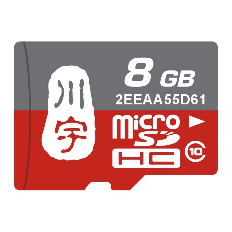
- 川宇 8G手机内存卡 8GTF卡存储卡 C10高速class10 micro SD卡:
4.3 制作一张带运行系统的TF卡
4.3.1 下载系统固件
访问下载地址下载需要的固件文件(officail-ROMs目录)和烧写工具(tools目录):
使用以下固件: nanopi-m1-plus-debian-sd4g.img.zip Debian系统固件 nanopi-m1-plus-ubuntu-core-qte-sd4g.img.zip 小型的Ubuntu core系统,内含Qt Embedded图形库 nanopi-m1-eflasher-sd8g.img.zip 基于Ubuntu core系统,具有烧写系统到eMMC 的功能
nanopi-m1-plus-android.img.zip Android系统固件 烧写工具: win32diskimager.rar Windows平台下的Debian系统烧写工具,Linux平台下可以用dd命令烧写Debian系统 PhoenixCard_V310.rar Windows平台下的Android系统烧写工具,注意:Android系统固件禁止在Linux平台下用dd命令烧写 HDDLLF.4.40.exe Windows平台下用于格式化TF卡的工具
4.3.2 TF卡启动系统
4.3.2.1 制作Debian系统TF卡
- 将固件nanopi-m1-plus-debian-sd4g.img.zip和烧写工具win32diskimager.rar分别解压,在Windows下插入TF卡(限4G及以上的卡),以管理员身份运行 win32diskimager 工具,
在win32diskimager工具的界面上,选择你的TF卡盘符,选择系统固件,点击 Write 按钮烧写即可。
- 当制作完成TF卡后,拔出TF卡插入M1+的BOOT卡槽,上电启动(注意,这里需要5V/2A的供电),你可以看到绿灯常亮以及蓝灯闪烁,这时你已经成功启动Debian系统。
注:Debian/Ubuntu系列的ROM都可以使用上述方法制作TF系统启动卡。
4.3.2.2 制作Android系统TF卡
- 以管理员权限运行HDDLLF.4.40软件,并且格式化SD卡,格式化后把卡从电脑拔出来,再把卡插入电脑,使用Windows自带的格式化程序把SD卡格式化成FAT32格式,格式化后把卡拔出来;
- 将固件nanopi-m1-plus-android.img.zip和烧写工具PhoenixCard_V310.rar分别解压,在Windows下插入TF卡(限4G及以上的卡)。
以管理员身份运行PhoenixCard, 在PhoenixCard的界面上,选择你的TF卡盘符,镜像文件选择为Android系统固件,烧写模式选择卡启动,点击 烧录 按钮烧写即可。
- 当制作完成TF卡后,拔出TF卡插入M1+的BOOT卡槽,上电启动(注意,这里需要5V/2A的供电),你可以看到绿灯常亮以及蓝灯闪烁,这时你已经成功启动Android系统。
注:每次烧写Android系统时,必须先格式化TF卡。
4.3.3 烧写系统到eMMC
- 将固件nanopi-m1-eflasher-sd8g.img.zip和烧写工具win32diskimager.rar分别解压,在Windows下插入TF卡(限8G及以上的卡),以管理员身份运行 win32diskimager 工具,
在win32diskimager工具的界面上,选择你的TF卡盘符,选择系统固件,点击 Write 按钮烧写即可。
- 当制作完成TF卡后,拔出TF卡插入M1+的BOOT卡槽,上电启动(注意,这里需要5V/2A的供电),你可以看到绿灯常亮以及蓝灯闪烁,这时你已经成功启动eflasher系统。
- 接上HDMI显示器和USB鼠标,在显示器上选择需要烧写到eMMC的系统,如下:
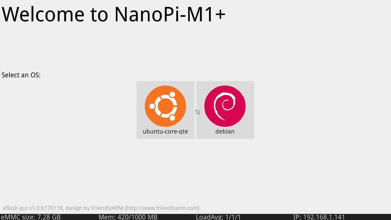
如果不想连接HDMI,可以在命令行终端中通过执行下列命令进行烧写:
eflasher
输入数字并回车选择想要安装到eMMC的系统,然后输入yes并回车确定开始烧写。等待烧写完毕后,断电并从BOOT卡槽中取出TF卡,此时再上电就会从eMMC启动系统了。
5 Debian系统的使用
5.1 运行Debian
- 当成功在TF卡/eMMC中安装Debian系统后,为M1+连接HDMI显示器及网线,最后连接电源(5V 2A),可以看到板上的蓝色LED闪烁,这说明系统已经开始启动了,同时电视上也将能看到系统启动的画面。
1)要在电视上进行操作,你需要连接USB鼠标和键盘.
2)如果您需要进行内核开发,你最好选购一个串口配件,连接了串口,则可以通过终端对M1+进行操作。
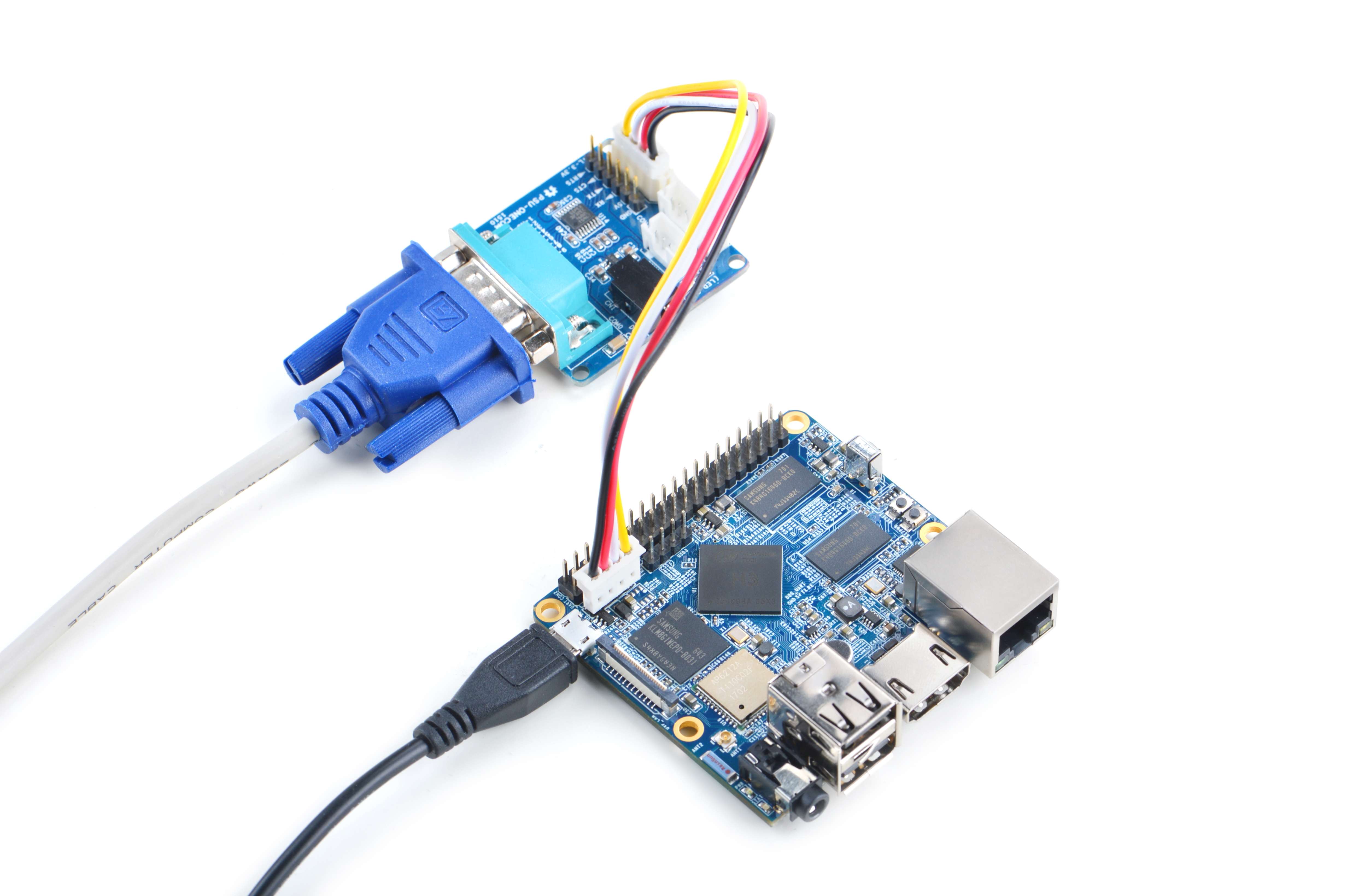
- 以下是串口的接法,接上串口,即可调试。接上串口后你可以选择从串口模块的DC口或者从M1+的MicroUSB口进行供电:
- 如果提示输入密码,Debian的root和fa用户的默认密码都是两个字母fa。
- 更新软件包:
sudo apt-get update
5.2 扩展文件系统分区
第一次启动Debian系统时,系统会自动扩展文件系统分区,请耐心等待,TF卡/eMMC的容量越大,需要等待的时间越长,进入系统后执行下列命令查看文件系统分区大小:
df -h
5.3 连接有线网络
M1+在加电开机前如果已正确的连接网线,则系统启动时会自动获取IP地址,如果没有连接网线、没有DHCP服务或是其它网络问题,则会导致获取IP地址失败,同时系统启动会因此等待约15~60秒的时间。
- 配置MAC地址
板子没有提供有效的Ethernet的MAC地址,系统在连接网络时会自动生成一个随机的MAC地址,您可以修改 /etc/network/interfaces.d/eth0 ,配置一个固定的MAC地址:
vi /etc/network/interfaces.d/eth0
以下是配置文件的具体内容:
auto eth0
allow-hotplug eth0
iface eth0 inet dhcp
hwaddress 76:92:d4:85:f3:0f
其中"hwaddress" 就是用来指定MAC地址,"76:92:d4:85:f3:0f"是一个随机生成的地址,为防止冲突导致网络问题,请修改为一个不同的且有效的地址。
需要注意的一点是,MAC地址必须符合IEEE的规则,请不要随意指定,否则会出现无法获取IP地址、无法上网等问题。
修改完配置文件并保存后,可重启板子或直接下列命令重启网络服务:
systemctl restart networking
5.4 连接无线网络
用vi或在图形界面下用gedit编辑文件 /etc/wpa_supplicant/wpa_supplicant.conf, 在文件末尾填入路由器信息如下所示:
network={
        ssid="YourWiFiESSID"
        psk="YourWiFiPassword"
}
其中,YourWiFiESSID和YourWiFiPassword请替换成你要连接的无线AP名称和密码。
保存退出后,执行以下命令即可连接WiFi:
ifdown wlan0
ifup wlan0
如果你的WiFi密码中有特殊字符,或者你不希望明文存放密码,你可以使用wpa_passphrase命令为WiFi密码生成一个密钥(psk),用密钥来代替密码 ,在命令行下,可输入以下命令生成密钥:
wpa_passphrase YourWiFiESSID
在提示输入密码时,输入你的WiFi密码,再打开 /etc/wpa_supplicant/wpa_supplicant.conf 文件你会发现密钥已经被更新,你可以删除明文的密码了。
5.5 通过VNC和ssh登录Debian
如果你不想连接HDMI,可以使用手机或电脑到这里下载并安装一个名为VNC Viewer的软件,用VNC连接到M1+,默认的端口号为1,密码为:fa123456 。
以下是在iPhone上用VNC登录M1+的画面:
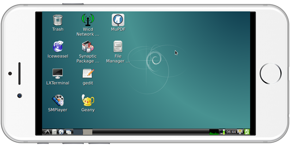
你也可以通过 ssh -l root 192.168.8.1 命令在终端上登录,默认的root用户密码是 fa 。请将192.168.8.1替换为实际IP地址。
5.6 HDMI输出声音
Debian系统默认从3.5mm耳机座输出声音,想从HDMI输出需要修改文件系统上的配置文件/etc/asound.conf如下:
pcm.!default {
    type hw
    card 1
    device 0
}

ctl.!default {
    type hw
    card 1
}
card 0代表3.5mm耳机孔,card 1代表HDMI音频。设置完成后需要重启系统才能生效。
5.7 测试GPU
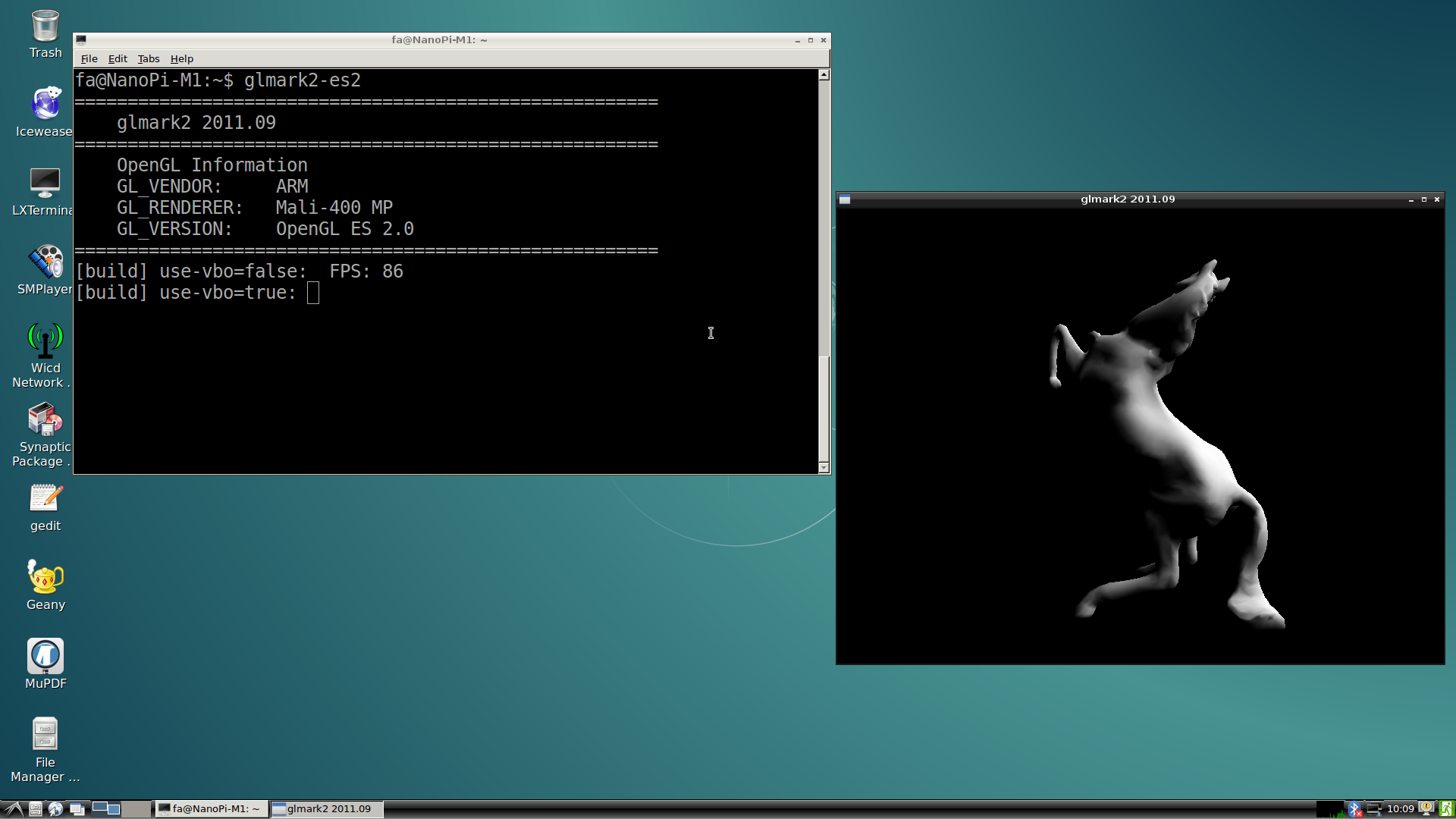
启动Debian系统,在HDMI界面下登录Debian,打开终端并运行命令:
glmark2-es2
5.8 测试VPU
访问此处下载地址的test-video目录下载视频文件,启动Debian系统,在HDMI界面下登录Debian,打开终端并运行命令:
sudo apt-get install mpv
video_play mpv ./big_buck_bunny_1080p_H264_AAC_25fps_7200K.MP4
经测试,可流畅硬解播放1080p视频。
5.9 连接USB WiFi
Debian系统已经支持市面上众多常见的USB WiFi,想知道你的USB WiFi是否可用只需将其接在M1+上即可,已测试过的USB WiFi型号如下:
序号 型号 1 RTL8188CUS/8188EU 802.11n WLAN Adapter 2 RT2070 Wireless Adapter 3 RT2870/RT3070 Wireless Adapter 4 RTL8192CU Wireless Adapter 5 小米WiFi mt7601
M1+ 上电启动连接上USB WiFi后,通过串口登录到系统,敲入以下命令可以查看到系统是否识别到USB WiFi,如果出现“wlan0”,则证明USB WiFi已被识别到:
ifconfig -a
用vi或在图形界面下用gedit编辑文件 /etc/wpa_supplicant/wpa_supplicant.conf, 在文件末尾填入路由器信息如下所示:
network={
        ssid="YourWiFiESSID"
        psk="YourWiFiPassword"
}
其中,YourWiFiESSID和YourWiFiPassword请替换成你要连接的无线AP名称和密码。
保存退出后,执行以下命令即可连接WiFi:
ifdown wlan0
ifup wlan0
如果你的WiFi密码中有特殊字符,或者你不希望明文存放密码,你可以使用wpa_passphrase命令为WiFi密码生成一个密钥(psk),用密钥来代替密码 ,在命令行下,可输入以下命令生成密钥:
wpa_passphrase YourWiFiESSID
在提示输入密码时,输入你的WiFi密码,再打开 /etc/wpa_supplicant/wpa_supplicant.conf 文件你会发现密钥已经被更新,你可以删除明文的密码了。
5.10 连接DVP摄像头模块(CAM500B)
CAM500B是一款500万像素摄像头模块,以DVP并行信号输出,详细信息请参考Matirx-CAM500B。
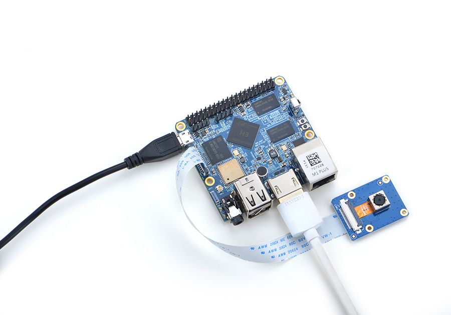
根据上图连接M1+和CAM500B,然后上电启动Debian系统,连接网络,以root用户登录终端并编译运行mjpg-streamer:
cd /root/mjpg-streamer
make
./start.sh
mjpg-streamer是一个开源的网络视频流服务器,在板子上成功运行mjpg-streamer后会打印下列信息:
 i: Using V4L2 device.: /dev/video0
 i: Desired Resolution: 1280 x 720
 i: Frames Per Second.: 30
 i: Format............: YUV
 i: JPEG Quality......: 90
 o: www-folder-path...: ./www/
 o: HTTP TCP port.....: 8080
 o: username:password.: disabled
 o: commands..........: enabled
假设M1+的IP地址为192.168.1.230,在PC的浏览器中输入 192.168.1.230:8080 就能浏览摄像头采集的画面了,效果如下:
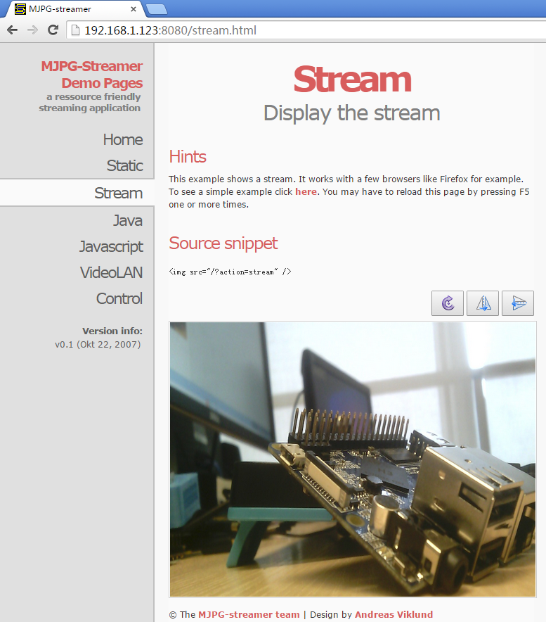
mjpg-streamer是用libjpeg对摄像头数据进行软编码,你可以使用ffmpeg对摄像头数据进行硬编码,这样能大大降低CPU的占用率并提高编码速度:
ffmpeg -t 30 -f v4l2 -channel 0 -video_size 1280x720 -i /dev/video0 -pix_fmt nv12 -r 30 -b:v 64k -c:v cedrus264 test.mp4
默认会录制30秒的视频,输入q能终止录制。录制完成后会在当前目录生成一个名为test.mp4的视频文件,可将其拷贝到PC上进行播放验证。
5.11 连接USB摄像头模块(FA-CAM202)
FA-CAM202是一款200万像素的USB摄像头模块。
启动Debian系统,在HDMI界面下登录Debian,打开终端并运行命令:
xawtv 0可以在HDMI界面下正常看到摄像头的预览内容。 注:这里的"0"指的是接进板子的摄像头为/dev/video0设备,请根据实际情况填写video索引号。
5.12 连接摄像头测试OpenCV
OpenCV的全称是Open Source Computer Vision Library,是一个跨平台的计算机视觉库。
执行以下步骤测试OpenCV:
- 连接网线,然后启动Debian系统,在HDMI界面下登录Debian。
- 安装opencv库,执行命令:
apt-get update
apt-get install libcv-dev libopencv-dev
- 参考前面章节,确保摄像头工作正常:
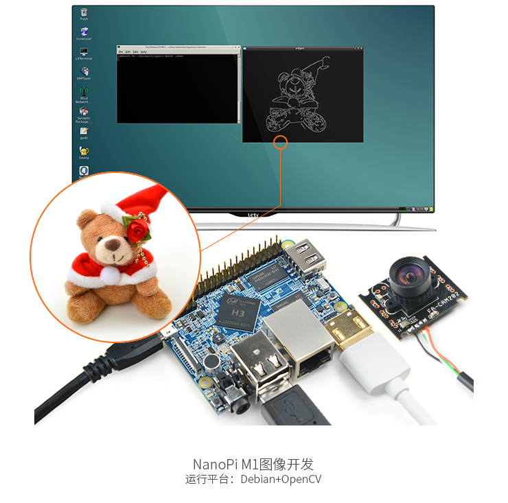
- 运行OpenCV官方C++示例代码,执行下列命令编译运行:
cd /home/fa/Documents/opencv-demo
make
./demo
5.13 命令行查看CPU工作温度
在串口终端执行如下命令,可以快速地获取CPU的当前温度和运行频率等信息:
cpu_freq
5.14 通过Rpi-Monitor查看系统状态
Debian系统里已经集成了Rpi-Monitor,该服务允许用户在通过浏览器查看开发板系统状态。
假设M1+的IP地址为192.168.1.230,在PC的浏览器中输入下述地址:
192.168.1.230:8888可以进入如下页面:
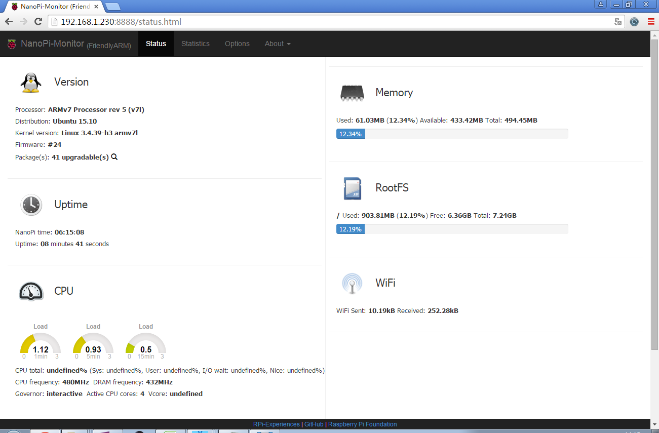
用户可以非常方便地查看到系统负载、CPU的频率和温度、可用内存、SD卡容量等信息。
6 如何编译Debian系统
6.1 准备工作
访问此处下载地址的sources/nanopi-h3-bsp目录,下载所有压缩文件,使用7-Zip工具解压后得到lichee目录和android目录,请务必保证这2个目录位于同一个目录中,如下:
ls ./
android lichee
也可以从github上克隆lichee源码:
git clone https://github.com/friendlyarm/h3_lichee.git lichee
注:lichee是全志为其CPU的板级支持包所起的项目名称,里面包含了U-boot,Linux等源码和众多的编译脚本。
6.2 安装交叉编译器
访问此处下载地址的toolchain目录,下载交叉编译器gcc-linaro-arm.tar.xz,将该压缩包放置在lichee/brandy/toochain/目录下即可,无需解压。
6.3 编译lichee源码
编译全志 H3 的BSP源码包必须使用64bit的Linux PC系统,并安装下列软件包,下列操作均基于Ubuntu-14.04 LTS-64bit:
sudo apt-get install gawk git gnupg flex bison gperf build-essential \
zip curl libc6-dev libncurses5-dev:i386 x11proto-core-dev \
libx11-dev:i386 libreadline6-dev:i386 libgl1-mesa-glx:i386 \
libgl1-mesa-dev g++-multilib mingw32 tofrodos \
python-markdown libxml2-utils xsltproc zlib1g-dev:i386
为Debian系统编译lichee源码包,进入lichee目录,执行命令:
cd lichee
./build.sh -p sun8iw7p1 -b nanopi-h3
该命令会为Debian系统一次性编译好U-boot、Linux内核和模块。
lichee目录里内置了交叉编译器,当使用build.sh脚本进行源码编译时,会自动使用该内置的编译器,所以无需手动安装编译器。
6.4 打包系统组件
./gen_script.sh -b nanopi-m1-plus
该命令会为U-boot打上全志系列CPU的硬件板级配置补丁,然后所有编译生成的可执行文件(包括U-boot、Linux内核)拷贝到lichee/tools/pack/out/目录以便进行统一管理。
下列命令可以更新TF卡上的U-boot:
./fuse_uboot.sh /dev/sdx
/dev/sdx请替换为实际的TF卡设备文件名。
内核boot.img和驱动模块均位于linux-3.4/output目录下,将boot.img拷贝到TF卡的boot分区的根目录即可更新内核。
6.5 编译U-boot
如果你想单独编译U-boot,可以执行命令:
./build.sh -p sun8iw7p1 -b nanopi-h3 -m uboot
./gen_script.sh -b nanopi-m1-plus
gen_script.sh脚本会为U-boot打上全志系列CPU的硬件板级配置补丁,只有打过补丁文件的U-boot才能烧写到TF卡中正常运行。 执行下列命令更新TF卡上的U-boot:
./fuse_uboot.sh /dev/sdx
/dev/sdx请替换为实际的TF卡设备文件名。
6.6 编译Linux内核
如果你想单独编译Linux内核,可以执行命令:
./build.sh -p sun8iw7p1 -b nanopi-h3 -m kernel
编译完成后内核boot.img和驱动模块均位于linux-3.4/output目录下,将boot.img拷贝到TF卡的boot分区的根目录即可。
6.7 清理lichee源码
./build.sh -p sun8iw7p1_linux -b nanopi-h3 -m clean
7 Android系统的使用
7.1 连接USB WiFi
Android系统目前仅支持型号为rtl8188etv/rtl8188eu的USB WiFi,即插即用。
7.2 使用红外遥控器(RC-100)
启动Android系统后,可用红外遥控器(型号为RC-100)进行远程操控。
RC-100上的按键功能如下:
按键名称 按键功能 POWER 开机/关机 F1 搜索 F2 打开浏览器 F3 进入/退出鼠标模式 UP 向上移动 DOWN 向下移动 LEFT 向左移动 RIGHT 向右移动 OK 确认 音量- 减小音量 音量静音 静音 音量+ 增大音量 SETTING 打开设置 HOME 回到主界面 BACK 返回上一个界面
Android系统第一次启动时,需要点击屏幕上的按钮完成教学示范,用户可以按下 F3 进入鼠标模式,然后配合上下左右和OK按键完成教学操作。
7.3 播放4K视频
访问此处下载地址的test-video目录,下载4K视频文件4K-Chimei-inn-60mbps.mp4,将其拷贝到SD卡或者U盘上。
在M1+上启动并运行Android系统,将带有视频文件的SD卡或者U盘接到M1+上,通过文件浏览器ESFileExplorer找到视频文件,点击视频文件并选择使用系统自带应用Gallery播放视频,即可观看影片。
经测试,将视频文件拷贝到U盘播放效果会更佳。
8 如何编译Android系统
8.1 准备工作
访问此处下载地址的sources/nanopi-h3-bsp目录,下载所有压缩文件,使用7-Zip工具解压后得到lichee目录和android目录,请务必保证这2个目录位于同一个目录中,如下:
ls ./
android lichee
也可以从github上克隆lichee源码:
git clone https://github.com/friendlyarm/h3_lichee.git lichee
注:lichee是全志为其CPU的板级支持包所起的项目名称,里面包含了U-boot,Linux等源码和众多的编译脚本。
编译全志 H3 的BSP源码包必须使用 64bit 的Linux系统,并安装下列软件包,下列操作均基于Ubuntu-14.04 LTS-64bit:
sudo apt-get install gawk git gnupg flex bison gperf build-essential \
zip curl libc6-dev libncurses5-dev:i386 x11proto-core-dev \
libx11-dev:i386 libreadline6-dev:i386 libgl1-mesa-glx:i386 \
libgl1-mesa-dev g++-multilib mingw32 tofrodos \
python-markdown libxml2-utils xsltproc zlib1g-dev:i386
8.2 安装交叉编译器
访问此处下载地址的toolchain目录,下载交叉编译器压缩包gcc-linaro-arm.tar.xz,然后将该压缩包放置在lichee/brandy/toochain/目录下即可,无需解压。
8.3 编译Android
- 搭建编译环境
搭建编译Android的环境建议使用64位的Ubuntu-14.04 LTS-64bit,安装需要的包即可。
sudo apt-get install bison g++-multilib git gperf libxml2-utils make python-networkx zip
sudo apt-get install flex libncurses5-dev zlib1g-dev gawk minicom
更多说明可查看:android_initializing。
- 安装JDK
使用JDK1.6.0_45版本,下载和安装说明请查看Oracle官方网址:Oracle JDK ,这里假设JDK已经成功安装到路径/usr/lib/jvm/下。
- 编译系统
cd lichee
export PATH=/usr/lib/jvm/jdk1.6.0_45/bin:$PATH
./gen_android_img.sh -b nanopi-m1-plus -t android
上述命令会编译lichee目录和android目录,编译完成后会在lichee/tools/pack/目录下生成Android系统固件sun8iw7p1_android_nanopi-h3_uart0.img。
8.4 清理lichee源码
./build.sh -p sun8iw7p1_android -b nanopi-h3 -m clean
9 更多OS
10 3D打印文件下载
- NanoPi M1 Plus 3D打印外壳:[1]
11 NanoPi M1 Plus初学者入门开发教程
- 《硬件编程开发教程》点击下载
12 资源链接
- H3芯片手册 Allwinner_H3_Datasheet_V1.2.pdf
- 模块介绍以及开发文档:
- 按键模块
- LED模块
- 模数转换
- 继电器模块
- 三轴重力加速度模块
- 三轴数字指南针模块
- 温度传感器模块
- 温湿度传感器模块
- 蜂鸣器
- 摇杆模块(Joystick)
- I2C(PCF8574)+LCD1602
- 声音传感器
- 超声波模块
- GPS模块
- 迷你扩展板Matrix - Compact Kit
- 火焰传感器
- CAM500 500万像素摄像头
- 滚珠开关模块
- 2'8 SPI Key TFT 2.8寸spi液晶屏
- 红外计数模块
- 红外接收模块
- 电机驱动器模块
- MQ-2 烟雾传感器模块
- MQ-3 气体传感器
- 单点电容式数字触摸传感器模块
- 光敏电阻模块
- 电位器模块
- 压力传感器模块
- RGB LED
- RTC模块
- Rotary Encoder
- 土壤湿度检测传感器模块
- 热敏电阻模块
- USB WiFi
- 水位/水滴识别检测传感器模块
13 更新日志
13.1 2017-02-04
- 修复Debian系统和Ubuntu-Core系统USB WiFi无法使用的问题;
- 将Ubuntu-Core系统的版本号从15.10升级到16.04;
