Difference between revisions of "Matrix - IR Counter"
From FriendlyELEC WiKi
(→工作原理) |
(→硬件连接) |
||
| Line 25: | Line 25: | ||
* U型对射光电开关传感器的发射器和接收器分别位于U型槽的两边,发射管发出红外信号并形成一光轴,当被检测物体经过U型槽且阻断光轴时,光电开关就产生了开关量信号。U型槽没有被阻挡时,接收管能接收到红外信号,模块输出高电平,U型槽被阻挡时,接收管不能接收到红外信号,模块输出低电平。 | * U型对射光电开关传感器的发射器和接收器分别位于U型槽的两边,发射管发出红外信号并形成一光轴,当被检测物体经过U型槽且阻断光轴时,光电开关就产生了开关量信号。U型槽没有被阻挡时,接收管能接收到红外信号,模块输出高电平,U型槽被阻挡时,接收管不能接收到红外信号,模块输出低电平。 | ||
| − | == | + | ==Applications== |
| − | === | + | ===Connect to NanoPi M1=== |
| − | + | Refer to the following connection diagram to connect the module to the NanoPi M1:<br> | |
[[File:Matrix-IR_Counter_nanopi_m1.jpg|frameless|600px|Matrix-IR_Counter_nanopi_m1]] | [[File:Matrix-IR_Counter_nanopi_m1.jpg|frameless|600px|Matrix-IR_Counter_nanopi_m1]] | ||
| − | + | Connection Details: | |
{| class="wikitable" | {| class="wikitable" | ||
|- | |- | ||
| Line 42: | Line 42: | ||
|} | |} | ||
| − | === | + | ===Connect to NanoPi 2=== |
| − | + | Refer to the following connection diagram to connect the module to the NanoPi 2:<br> | |
[[File:Matrix-IR_Counter_nanopi_2.jpg|frameless|600px|Matrix-IR_Counter_nanopi_2]] | [[File:Matrix-IR_Counter_nanopi_2.jpg|frameless|600px|Matrix-IR_Counter_nanopi_2]] | ||
| − | + | Connection Details: | |
{| class="wikitable" | {| class="wikitable" | ||
|- | |- | ||
| Line 58: | Line 58: | ||
|} | |} | ||
| − | === | + | ===Connect to NanoPi M2 / NanoPi 2 Fire=== |
| − | NanoPi | + | Refer to the following connection diagram to connect the module to the NanoPi M2/ NanoPi 2 Fire.<br> |
| − | + | ||
[[File:Matrix-IR_Counter_nanopi_m2.jpg|frameless|600px|Matrix-IR_Counter_nanopi_m2]] | [[File:Matrix-IR_Counter_nanopi_m2.jpg|frameless|600px|Matrix-IR_Counter_nanopi_m2]] | ||
| − | + | Connection Details: | |
{| class="wikitable" | {| class="wikitable" | ||
|- | |- | ||
| Line 75: | Line 74: | ||
|} | |} | ||
| − | === | + | ===Connect to NanoPC-T2=== |
| − | + | Refer to the following connection diagram to connect the module to the NanoPC-T2:<br> | |
[[File:Matrix-IR_Counter_NanoPC-T2.jpg|frameless|600px|Matrix-IR_Counter_NanoPC-T2]] | [[File:Matrix-IR_Counter_NanoPC-T2.jpg|frameless|600px|Matrix-IR_Counter_NanoPC-T2]] | ||
| − | + | Connection Details: | |
{| class="wikitable" | {| class="wikitable" | ||
|- | |- | ||
Revision as of 03:55, 21 June 2016
Contents
1 Introduction
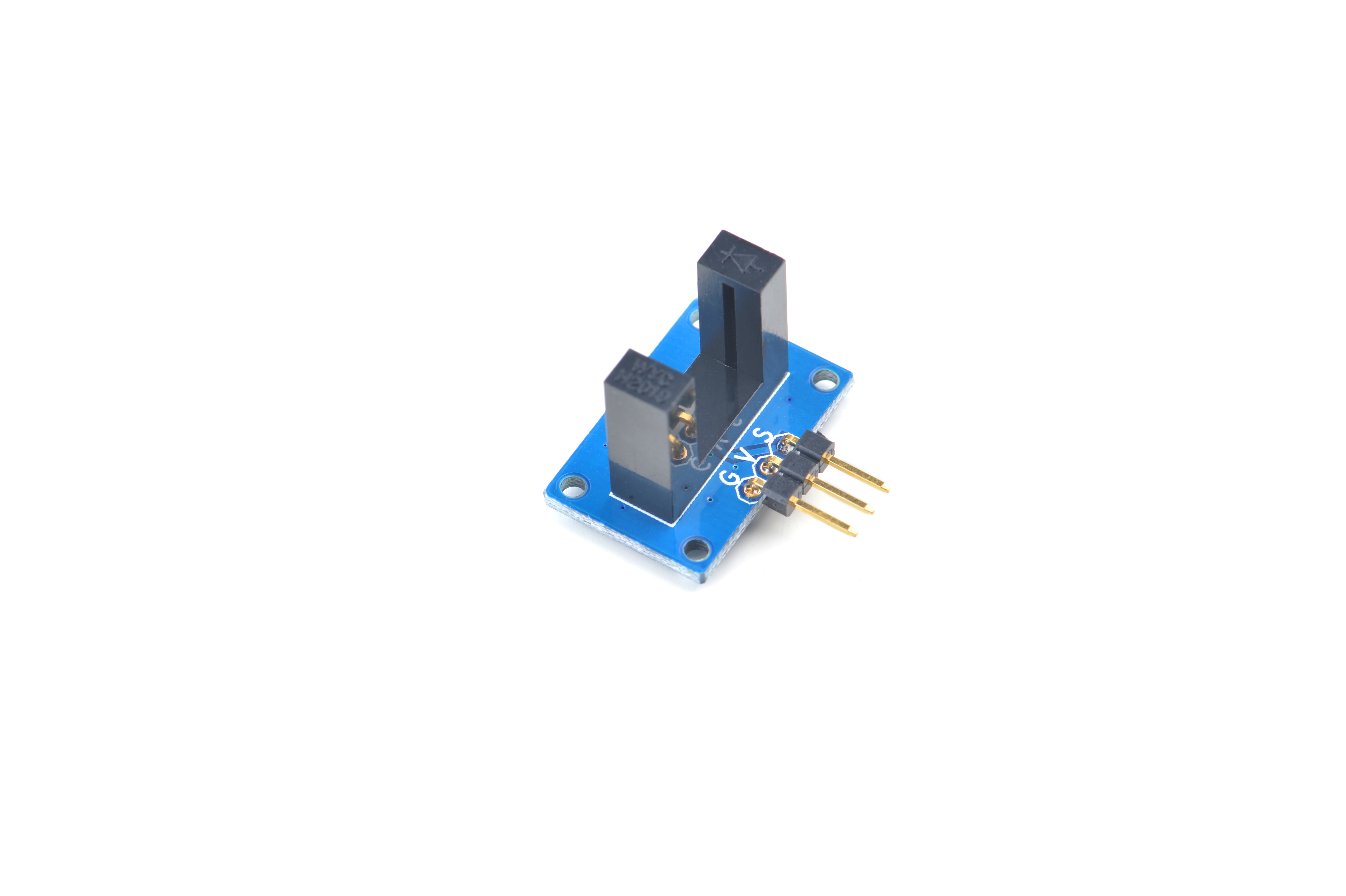
- The Matrix IR_Counter uses a U type infrared beam photoelectric sensor. It has a 5 pin 2.54 mm pitch pin-header. Pin V is power supply and Pin G is ground. When there is no presence of an object Pin S outputs high
2 Features
- GPIO interface
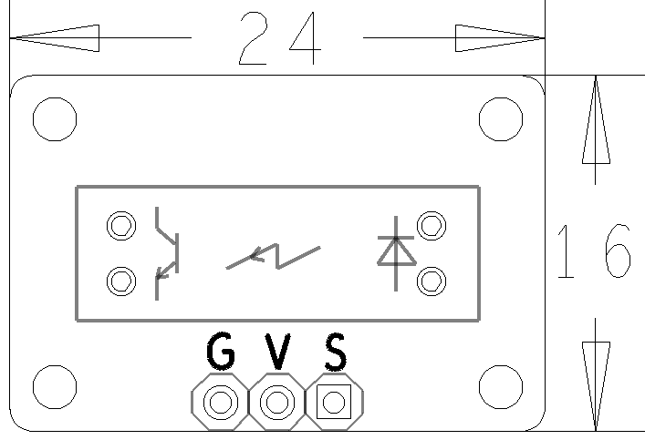
- PCB dimension(mm): 16 x 24 mm
- Pin Description:
| Pin | Description |
| S | Digital Output |
| V | Supply Voltage 5V |
| G | Ground |
3 Basic Device Operation
- U型对射光电开关传感器的发射器和接收器分别位于U型槽的两边,发射管发出红外信号并形成一光轴,当被检测物体经过U型槽且阻断光轴时,光电开关就产生了开关量信号。U型槽没有被阻挡时,接收管能接收到红外信号,模块输出高电平,U型槽被阻挡时,接收管不能接收到红外信号,模块输出低电平。
4 Applications
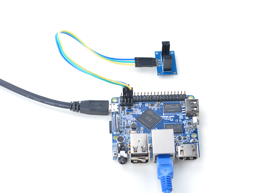
4.1 Connect to NanoPi M1
Refer to the following connection diagram to connect the module to the NanoPi M1:

Connection Details:
| Matrix-IR_Counter | NanoPi M1 |
| S | Pin7 |
| V | Pin4 |
| G | Pin6 |
4.2 Connect to NanoPi 2
Refer to the following connection diagram to connect the module to the NanoPi 2:
Matrix-IR_Counter_nanopi_2
Connection Details:
| Matrix-IR_Counter | NanoPi 2 |
| S | Pin7 |
| V | Pin4 |
| G | Pin6 |
4.3 Connect to NanoPi M2 / NanoPi 2 Fire
Refer to the following connection diagram to connect the module to the NanoPi M2/ NanoPi 2 Fire.

Connection Details:
| Matrix-IR_Counter | NanoPi M2 |
| S | Pin7 |
| V | Pin4 |
| G | Pin6 |
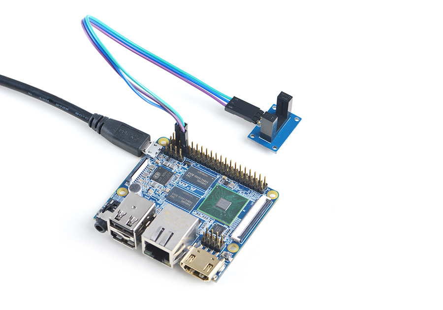
4.4 Connect to NanoPC-T2
Refer to the following connection diagram to connect the module to the NanoPC-T2:
Matrix-IR_Counter_NanoPC-T2
Connection Details:
| Matrix-IR_Counter | NanoPC-T2 |
| S | Pin15 |
| V | Pin29 |
| G | Pin30 |
5 编译运行测试程序
启动开发板并运行Debian系统,进入系统后克隆Matrix代码仓库:
$ apt-get update && apt-get install git
$ git clone https://github.com/friendlyarm/matrix.git
克隆完成后会得到一个名为matrix的目录。
编译并安装Matrix:
$ cd matrix
$ make && make install
运行测试程序:
$ matrix-gpio_int注意:此模块并不支持热插拔,启动系统前需要确保硬件连接正确。
运行效果如下:
Waiting event...
Device[0] value is 1
当有物体阻挡在模块中间时会检测到事件。
6 代码说明
所有的开发板都共用一套Matrix代码,本模块的测试示例代码为matrix-gpio_int,内容如下:
int main(int argc, char ** argv)
{
    int i, board;
    int retSize = -1;
    char value[ARRAY_SIZE(dev)];

    if ((board = boardInit()) < 0) {
        printf("Fail to init board\n");
        return -1;
    }

    if (argc == 2)
        dev[0].pin = atoi(argv[1]);
    system("modprobe "DRIVER_MODULE);
    signal(SIGINT, intHandler);
    if (board == BOARD_NANOPI_T2)
        dev[0].pin = GPIO_PIN(15);
    printf("Use GPIO_PIN(%d)\n", dev[0].pin);
    if ((devFD =sensorInit(dev, ARRAY_SIZE(dev))) == -1) {
        printf("Fail to init sensor\n");
        goto err;
    }
    printf("Waiting event...\n");
    if ((retSize = sensorRead(devFD, value, ARRAY_SIZE(dev))) == -1) {
        printf("Fail to read sensors\n");
    }
    if (retSize > 0) {
        i = 0;
        for (i=0; i<retSize; i++) {
            printf("Device[%d] value is %d\n", i, value[i]);
        }
    }
    sensorDeinit(devFD);
err:
    system("rmmod "DRIVER_MODULE);
    return 0;
}
API说明参考维基:Matrix API reference manual

