Difference between revisions of "NanoPi M1"
(→Make an Installation MicroSD Card) |
(→Debian系统的使用) |
||
| Line 172: | Line 172: | ||
* Please insert this card to your NanoPi M1 and power on (with a 5V/2A power source). If the green LED is on and the blue LED is blinking this indicates your NanoPi M1 is successfully booted.<br /> | * Please insert this card to your NanoPi M1 and power on (with a 5V/2A power source). If the green LED is on and the blue LED is blinking this indicates your NanoPi M1 is successfully booted.<br /> | ||
| − | == | + | ==Play with Debian== |
| − | === | + | ===Ethernet Connection=== |
| − | NanoPi | + | If the NanoPi M1 is connected to a network via Ethernet before it is powered on it will automatically obtain an IP after it is powered on. If it is not connected via Ethernet or its DHCP is not activated obtaining an IP will fail and system will hang on for about 15 to 60 seconds |
| − | * 1) | + | * 1) Setup MAC Address |
| − | + | The NanoPi M1 by default doesn't have a valid MAC address. If the board connects a network successfully it will automatically generates a random MAC in "/etc/network/interfaces.d/eth0". Users can change it to a self-defined valid one: | |
<syntaxhighlight lang="bash"> | <syntaxhighlight lang="bash"> | ||
vi /etc/network/interfaces.d/eth0 | vi /etc/network/interfaces.d/eth0 | ||
</syntaxhighlight> | </syntaxhighlight> | ||
| − | + | Here is the content of a sample configuration file: | |
<syntaxhighlight lang="bash"> | <syntaxhighlight lang="bash"> | ||
auto eth0 | auto eth0 | ||
| Line 187: | Line 187: | ||
hwaddress 76:92:d4:85:f3:0f | hwaddress 76:92:d4:85:f3:0f | ||
</syntaxhighlight> | </syntaxhighlight> | ||
| − | + | The "hwaddress" specifies the MAC address. Here the "76:92:d4:85:f3:0f" is a random MAC. We suggest users change it to a valid one.<br/> | |
| − | + | Note: when you reset the MAC please make sure your MAC meets IEEE's definition otherwise it will cause unexpected issues. | |
| − | + | After you make your change, save, exit and reboot your board or run the following commands to restart the network: | |
<syntaxhighlight lang="bash"> | <syntaxhighlight lang="bash"> | ||
systemctl restart networking | systemctl restart networking | ||
</syntaxhighlight> | </syntaxhighlight> | ||
| − | === | + | |
| + | ===Test GPU=== | ||
启动Debian系统,在HDMI输出的界面下登录Debian,打开终端并运行程序glmark2-es2: | 启动Debian系统,在HDMI输出的界面下登录Debian,打开终端并运行程序glmark2-es2: | ||
<syntaxhighlight lang="bash"> | <syntaxhighlight lang="bash"> | ||
Revision as of 07:30, 22 March 2016
Contents
1 Introduction
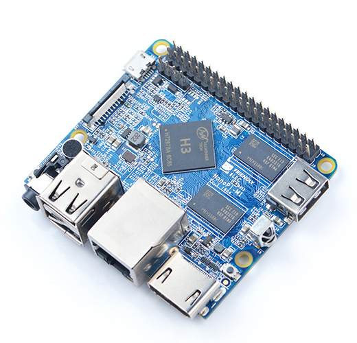
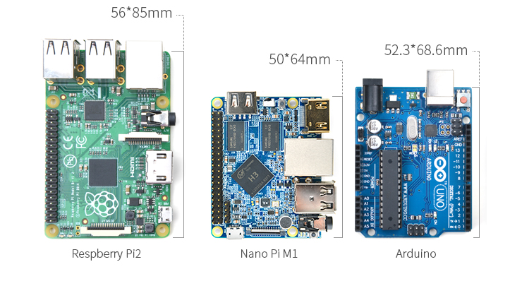
- The NanoPi M1 is an Allwinner H3 based ARM board designed and released by FriendlyARM for hobbyists, makers and electronic fans. It is only two thirds the size of the Raspberry Pi. It is open source. It works with Ubuntu MATE, Debian and etc.
- The NanoPi M1 uses Allwinner’s H3 Soc. It integrates Ethernet, IR receiver, video/audio output and supports HDMI and AVOUT. It can be powered via the MicroUSB port
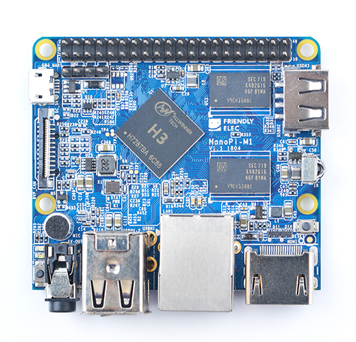
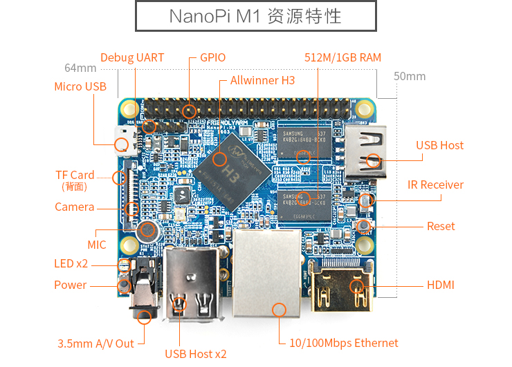
- In such a small board it still integrates rich interfaces and ports. Besides the popular HDMI, Ethernet, USB-Host, USB-OTG, DVP camera interface and AVOUT (audio and video) it has an onboard Microphone, IR receiver, a serial debug port and a Raspberry Pi compatible 40 pin GPIO pin header.
2 Features
- CPU: Allwinner H3, Quad-core Cortex-A7@1.2GHz
- GPU: Mali400MP2@600MHz,Supports OpenGL ES2.0
- DDR3 RAM: 512MB
- Connectivity: 10/100M Ethernet
- Audio: 3.5mm audio jack/Via HDMI
- Microphone: Onboard microphone
- IR Receiver: Onboard IR receiver
- USB Host:Type A, USB 2.0 x 3
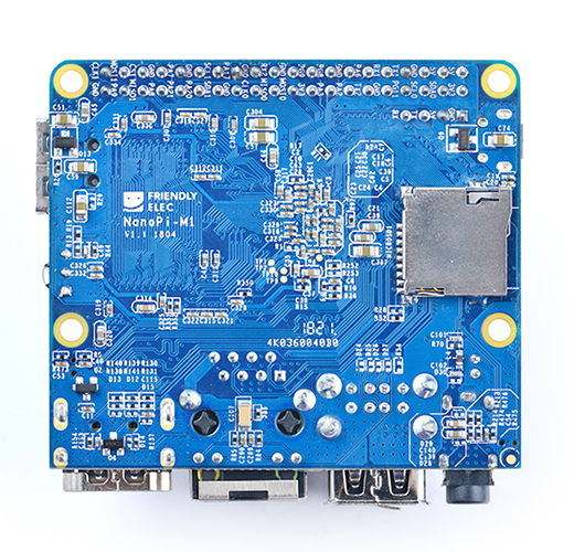
- MicroSD Slot x 1
- MicroUSB: for data transmission and power input, OTG
- Video Output: HDMI 1.4 1080P, CVBS
- DVP Camera Interface: 24pin, 0.5mm pitch FPC seat
- Debug Serial Port: 4Pin, 2.54mm pitch pin header
- GPIO: 2.54mm spacing 40pin, compatible with Raspberry Pi's GPIO. It includes UART, SPI, I2C, IO etc
- User Key: Power LED x 1, Reset x 1
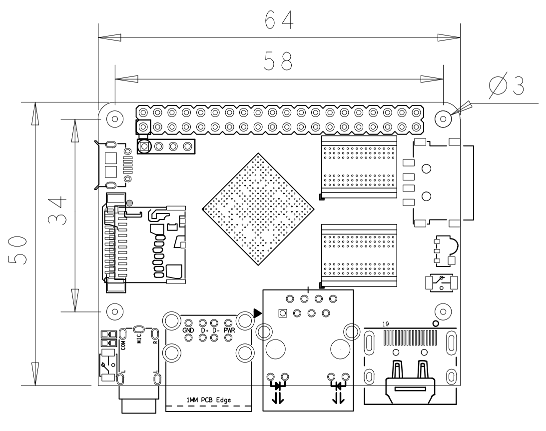
- PC Size: 64 x 50mm
- Power Supply: DC 5V/2A
- OS/Software: u-boot,Ubuntu MATE,Debian
3 Diagram, Layout and Dimension
3.1 Layout
- GPIO Pin Spec
Pin# Name Pin# Name 1 SYS_3.3V 2 VDD_5V 3 I2C0_SDA 4 VDD_5V 5 I2C0_SCL 6 GND 7 GPIOG11 8 UART1_TX/GPIOG6 9 GND 10 UART1_RX/GPIOG7 11 UART2_TX/GPIOA0 12 PWM1/GPIOA6 13 UART2_RTS/GPIOA2 14 GND 15 UART2_CTS/GPIOA3 16 UART1_RTS/GPIOG8 17 SYS_3.3V 18 UART1_CTS/GPIOG9 19 SPI0_MOSI/GPIOC0 20 GND 21 SIP0_MISO/GPIOC1 22 UART2_RX/GPIOA1 23 SPI0_CLK/GPIOC29 24 SPI0_CS/GPIOC3 25 GND 26 SPDIF-OUT/GPIOA17 27 I2C1_SDA/GPIOA19 28 I2C1_SCL/GPIOA18 29 GPIOA20 30 GND 31 GGPIOA21 32 GPIOA7 33 GPIOA8 34 GND 35 UART3_CTS/SPI1_MISO/GPIOA16 36 UART3_TX/SPI1_CS/GPIOA13 37 GPIOA9 38 UART3_RTS/SPI1_MOSI/GPIOA15 39 GND 40 UART3_RX/SPI1_CLK/GPIOA14
- Debug Port(UART0)
Pin# Name 1 GND 2 VDD_5V 3 UART_TXD0 4 UART_RXD0
- DVP Camera IF Pin Spec
Pin# Name Description 1, 2 SYS_3.3V 3.3V power output, to camera modules 7,9,13,15,24 GND Gound, 0V 3 I2C2_SCL I2C Clock Signal 4 I2C2_SDA I2C Data Signal 5 GPIOE15 Regular GPIO, control signals output to camera modules 6 GPIOE14 Regular GPIO, control signals output to camera modules 8 MCLK Clock signals output to camera modules 10 NC Not Connected 11 VSYNC vertical synchronization to CPU from camera modules 12 HREF/HSYNC HREF/HSYNC signal to CPU from camera modules 14 PCLK PCLK signal to CPU from camera modules 16-23 Data bit7-0 data signals
- Note:
- SYS_3.3V: 3.3V power output
- VDD_5V: 5V power input/output. When the external device’s power is greater than the MicroUSB’s the external device is charging the board otherwise the board powers the external device. The input range is 4.7V ~ 5.6V
- All pins are 3.3V and output current is 5mA. It can drive small loads.可以带动小负荷模块,io都不能带负载
- For more details please refer to the document: NanoPi-M1-1603-Schematic.pdf
3.2 Board Dimension
- For more details please refer to: pcb file in dxf
4 Get Started
4.1 Essentials You Need
Before play with your NanoPi M1 please get the following items ready
- NanoPi M1
- microSD Card/TFCard: Class 10 or Above, minimum 8GB SDHC
- microUSB power. A 5V/2A power is a must
- HDMI monitor
- USB keyboard and mouse
- A Host running Ubuntu 14.04 64 bit system
4.2 TF Cards We Tested
To make your NanoPi M1 boot and run fast we highly recommand you use a Class10 8GB SDHC TF card or a better one. The following cards are what we used in all our test cases presented here:
- SanDisk TF 8G Class10 Micro/SD TF card:
- SanDisk TF128G MicroSDXC TF 128G Class10 48MB/S:
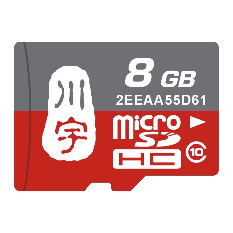
- 川宇 8G C10 High Speed class10 micro SD card:
4.3 Make an Installation MicroSD Card
4.3.1 Under Windows
Please get the following files from here:[http://wiki.friendlyarm.com/wiki/nanopi2/download/ to download image files.
Image Files nanopi-m1-debian-sd4g.img.zip Debian Image Files Flash Utility: win32diskimager.rar Windows utility. Under Linux users can use "dd"
- Please uncompress these files. Insert an SD card(at least 4G) to a Windows PC, run the win32diskimager utility as administrator,On the utility's main window select your SD card's drive and the image files and click on "write" to start flashing the SD card.
- Please insert this card to your NanoPi M1 and power on (with a 5V/2A power source). If the green LED is on and the blue LED is blinking this indicates your NanoPi M1 is successfully booted.
5 Play with Debian
5.1 Ethernet Connection
If the NanoPi M1 is connected to a network via Ethernet before it is powered on it will automatically obtain an IP after it is powered on. If it is not connected via Ethernet or its DHCP is not activated obtaining an IP will fail and system will hang on for about 15 to 60 seconds
- 1) Setup MAC Address
The NanoPi M1 by default doesn't have a valid MAC address. If the board connects a network successfully it will automatically generates a random MAC in "/etc/network/interfaces.d/eth0". Users can change it to a self-defined valid one:
vi /etc/network/interfaces.d/eth0
Here is the content of a sample configuration file:
auto eth0
allow-hotplug eth0
iface eth0 inet dhcp
hwaddress 76:92:d4:85:f3:0f
The "hwaddress" specifies the MAC address. Here the "76:92:d4:85:f3:0f" is a random MAC. We suggest users change it to a valid one.
Note: when you reset the MAC please make sure your MAC meets IEEE's definition otherwise it will cause unexpected issues.
After you make your change, save, exit and reboot your board or run the following commands to restart the network:
systemctl restart networking
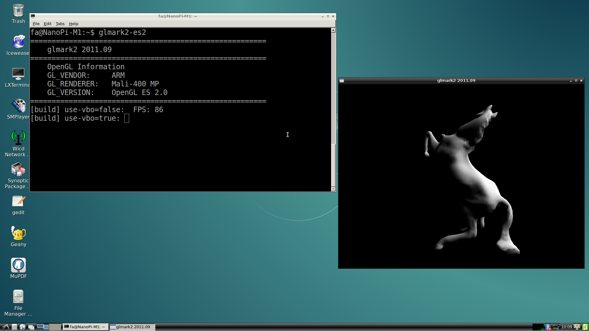
5.2 Test GPU
启动Debian系统,在HDMI输出的界面下登录Debian,打开终端并运行程序glmark2-es2:
glmark2-es2
5.3 测试VPU
访问此处下载地址下载视频文件。
启动Debian系统,在HDMI输出的界面下登录Debian,打开终端运行mplayer播放视频:
mplayer -vo vdpau -vc ffmpeg12vdpau,ffh264vdpau, ./big_buck_bunny_1080p_H264_AAC_25fps_7200K.MP4
经测试,可流畅播放1080p视频。
6 如何编译Debian系统
下载源码,进入目录lichee:
cd lichee6.1 编译完整源码
一次性编译整个源码包,包括U-boot、Linux Kernel和Module:
./build.sh -p sun8iw7p1 -b nanopi-h3
./gen_script.sh
gen_script.sh会打包所有可执行文件,并生成支持不同分辨率的script.bin。 script.bin是全志系列cpu的硬件板级配置文件,相关信息请查看script.bin
6.2 烧写系统到SD卡
烧写U-boot、Linux Kernel和script.bin到SD卡上:
./burn_into_sd.sh /dev/sdx
/dev/sdx请替换为实际的SD卡设备文件名,该脚本会烧写U-boot到SD卡中,并拷贝uImage和script.bin到SD卡boot分区。
6.3 编译U-boot
./build.sh -p sun8iw7p1 -b nanopi-h3 -m uboot
编译生成的可执行文件需打上补丁后才能烧写到SD卡上运行,执行./gen_script.sh脚本能完成打补丁的操作。
如何手动打补丁请查看H3_Manual_build_howto
6.4 编译Linux Kernel
./build.sh -p sun8iw7p1 -b nanopi-h3 -m kernel
编译完成后uImage和内核模块均位于linux-3.4/output目录下。
6.5 清理源码
./build.sh -p sun8iw7p1 -b nanopi-h3 -m clean
7 如何编译Android系统
8 更多OS
8.1 Ubuntu-Core
Ubuntu-Core是一个轻量级的Ubuntu系统,无桌面环境,可通过ssh登录。
仅提供给进阶爱好者交流使用,不对该系统提供专业技术支持。
- 访问此处下载地址下载系统固件。
- 将固件解压后,在Windows下使用友善官方提供 win32diskimager 工具烧写即可。
- 烧写完成后,将SD卡插入NanoPi M1,上电即可体验Ubuntu-Core。
- 登录账号:root或fa ; 登录密码:fa
8.2 Ubuntu-MATE
Ubuntu-MATE基于Ubuntu系统,使用的桌面环境是MATE-desktop,界面简洁易用,需配合HDMI使用,可通过ssh登录。
仅提供给进阶爱好者交流使用,不对该系统提供专业技术支持。
- 访问此处下载地址下载系统固件。
- 将固件解压后,在Windows下使用友善官方提供 win32diskimager 工具烧写Ubuntu-MATE即可。
- 烧写完成后,将SD卡插入NanoPi M1,上电即可体验Ubuntu-MATE。
- 登录账号:root或fa ; 登录密码:fa
9 Resources
- Schematic NanoPi-M1-1603-Schematic.pdf
- Dimensional Diagram pcb file in dxf
- Allwinner H3 datasheet Allwinner_H3_Datasheet_V1.2.pdf
