Difference between revisions of "Matrix - Potentiometer"
From FriendlyELEC WiKi
| Line 30: | Line 30: | ||
*This module mainly contains a potentiometer where the resistance changes with changes between the contact and one end terminal. | *This module mainly contains a potentiometer where the resistance changes with changes between the contact and one end terminal. | ||
| + | |||
| + | ==硬件连接== | ||
| + | 模块Matrix-Potentiometer输出的是模拟信号,需要使用ADC转换模块Matrix-Analog_to_Digital_Converter将模拟信号转换为数字信号。<br> | ||
| + | 关于模块Matrix-Analog_to_Digital_Converter的使用方法可参考wiki:[[Matrix_-_Analog_to_Digital_Converter/zh|Matrix-Analog_to_Digital_Converter]]。<br> | ||
| + | |||
| + | ===连接NanoPi M1=== | ||
| + | 参考下图连接模块:<br> | ||
| + | [[File:Matrix-Potentiometer_nanopi_m1.jpg|frameless|600px|Matrix-Potentiometer_nanopi_m1]] | ||
| + | |||
| + | 连接说明: | ||
| + | {| class="wikitable" | ||
| + | |- | ||
| + | |Matrix-Potentiometer || | ||
| + | |- | ||
| + | |GND || NanoPi M1 Pin9 | ||
| + | |- | ||
| + | |5V || NanoPi M1 Pin2 | ||
| + | |- | ||
| + | |S || Matrix-Analog_to_Digital_Converter A0 | ||
| + | |} | ||
| + | |||
| + | ===连接NanoPi 2=== | ||
| + | 参考下图连接模块:<br> | ||
| + | [[File:Matrix-Potentiometer.jpg|frameless|600px|Matrix-Potentiometer]] | ||
| + | |||
| + | 连接说明: | ||
| + | {| class="wikitable" | ||
| + | |- | ||
| + | |Matrix-Potentiometer || | ||
| + | |- | ||
| + | |GND || NanoPi 2 Pin9 | ||
| + | |- | ||
| + | |5V || NanoPi 2 Pin2 | ||
| + | |- | ||
| + | |S || Matrix-Analog_to_Digital_Converter A0 | ||
| + | |} | ||
| + | |||
| + | ===连接NanoPi M2 / NanoPi 2 Fire=== | ||
| + | NanoPi M2和NanoPi 2 Fire的40 Pin引脚定义是一模一样的,所以它们操作Matrix配件的步骤是一样的,这里仅以NanoPi M2为例。<br> | ||
| + | 参考下图连接模块:<br> | ||
| + | [[File:Matrix-Potentiometer_nanopi_m2.jpg|frameless|600px|Matrix-Potentiometer_nanopi_m2]] | ||
| + | |||
| + | 连接说明: | ||
| + | {| class="wikitable" | ||
| + | |- | ||
| + | |Matrix-Potentiometer || | ||
| + | |- | ||
| + | |GND || NanoPi M2 Pin9 | ||
| + | |- | ||
| + | |5V || NanoPi M2 Pin2 | ||
| + | |- | ||
| + | |S || Matrix-Analog_to_Digital_Converter A0 | ||
| + | |} | ||
| + | |||
| + | ===连接NanoPC-T2=== | ||
| + | 参考下图连接模块:<br> | ||
| + | [[File:Matrix-Potentiometer_NanoPC-T2.jpg|frameless|600px|Matrix-Potentiometer_NanoPC-T2]] | ||
| + | |||
| + | 连接说明: | ||
| + | {| class="wikitable" | ||
| + | |- | ||
| + | |Matrix-Potentiometer || | ||
| + | |- | ||
| + | |GND || NanoPC-T2 USB Host GND | ||
| + | |- | ||
| + | |5V || NanoPC-T2 USB Host 5V | ||
| + | |- | ||
| + | |S || Matrix-Analog_to_Digital_Converter A0 | ||
| + | |} | ||
| + | |||
| + | ==编译运行测试程序== | ||
| + | 启动开发板并运行Debian系统,进入系统后克隆Matrix代码仓库: | ||
| + | <syntaxhighlight lang="bash"> | ||
| + | $ apt-get update && apt-get install git | ||
| + | $ git clone https://github.com/friendlyarm/matrix.git | ||
| + | </syntaxhighlight> | ||
| + | 克隆完成后会得到一个名为matrix的目录。 | ||
| + | |||
| + | 编译并安装Matrix: | ||
| + | <syntaxhighlight lang="bash"> | ||
| + | $ cd matrix | ||
| + | $ make && make install | ||
| + | </syntaxhighlight> | ||
| + | |||
| + | 运行测试程序: | ||
| + | <syntaxhighlight lang="bash"> | ||
| + | $ matrix-adc | ||
| + | </syntaxhighlight> | ||
| + | 注意:此模块并不支持热插拔,启动系统前需要确保硬件连接正确。<br> | ||
| + | 运行效果如下:<br> | ||
| + | <syntaxhighlight lang="bash"> | ||
| + | The channel0 value is 2460 | ||
| + | </syntaxhighlight> | ||
| + | |||
| + | ==代码说明== | ||
| + | 所有的开发板都共用一套Matrix代码,本模块的测试示例代码为matrix-analog_to_digital_converter,内容如下: | ||
| + | <syntaxhighlight lang="c"> | ||
| + | int main(int argc, char ** argv) | ||
| + | { | ||
| + | int i = 0; | ||
| + | int value = 0; | ||
| + | int channel = 0; | ||
| + | |||
| + | if (boardInit() < 0) { | ||
| + | printf("Fail to init board\n"); | ||
| + | return -1; | ||
| + | } | ||
| + | |||
| + | if (argc == 2) | ||
| + | channel = atoi(argv[1]); | ||
| + | system("modprobe "DRIVER_MODULE); | ||
| + | signal(SIGINT, intHandler); | ||
| + | for (i=0; i<ADC_READ_TIMES; i++) { | ||
| + | if (pcf8591Read(channel, &value) != -1) { | ||
| + | printf("The channel%d value is %d\n", channel, value); | ||
| + | } else { | ||
| + | printf("Fail to get channel%d value\n", channel); | ||
| + | } | ||
| + | } | ||
| + | system("rmmod "DRIVER_MODULE); | ||
| + | |||
| + | return 0; | ||
| + | } | ||
| + | </syntaxhighlight> | ||
| + | API说明参考维基:[[Matrix API reference manual/zh|Matrix API reference manual]] <br> | ||
| + | |||
| + | ==Resources== | ||
| + | |||
| + | <!--- | ||
==Download Matrix Source Code== | ==Download Matrix Source Code== | ||
All the matrix modules' code samples are open source. They are maintained on GitHub :https://github.com/friendlyarm/matrix.git <br> | All the matrix modules' code samples are open source. They are maintained on GitHub :https://github.com/friendlyarm/matrix.git <br> | ||
| Line 145: | Line 274: | ||
} | } | ||
</syntaxhighlight> | </syntaxhighlight> | ||
| + | ---> | ||
==Update Log== | ==Update Log== | ||
===Feb-24-2016=== | ===Feb-24-2016=== | ||
* Added link to the Chinese version | * Added link to the Chinese version | ||
Revision as of 14:10, 23 June 2016
Contents
1 Introduction
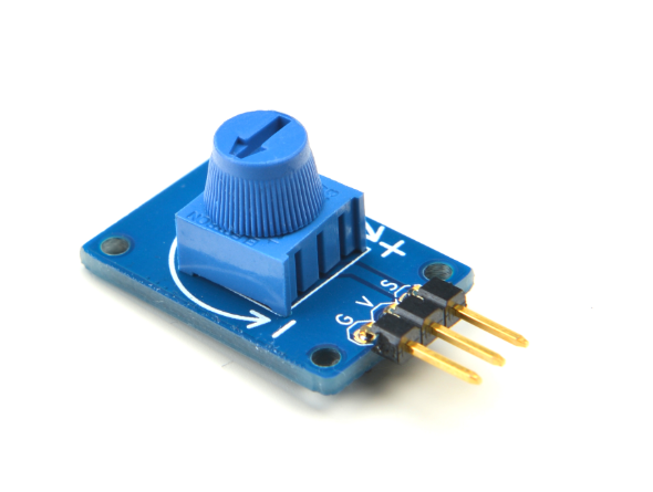
- The Matrix-Potentiometer module is a Potentiometer module. It can be used in audio control, motion control, transducers, computation and etc.
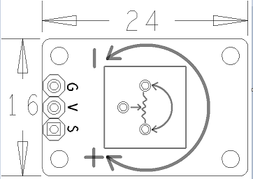
- 3 Pin 2.54mm spacing pin header, V is supply voltage, G is ground and S is output analog signal. Users can convert output analog signals to digital signals via ADC conversion.
- Output Voltage: 0 ~ Vcc
2 Features
- GPIO
- Small
- 2.54mm spacing pin header
- PCB Dimension(mm): 8 x 24
- Pin Description:
| Pin | Description |
| S | Analog GPIO |
| V | Supply Voltage 5V |
| G | Ground |
3 Basic Device Operation
- A potentiometer is a three-terminal resistor with a sliding or rotating contact that forms an adjustable voltage divider.If only two terminals are used, one end and the wiper, it acts as a variable resistor or rheostat.
- This module mainly contains a potentiometer where the resistance changes with changes between the contact and one end terminal.
4 硬件连接
模块Matrix-Potentiometer输出的是模拟信号,需要使用ADC转换模块Matrix-Analog_to_Digital_Converter将模拟信号转换为数字信号。
关于模块Matrix-Analog_to_Digital_Converter的使用方法可参考wiki:Matrix-Analog_to_Digital_Converter。
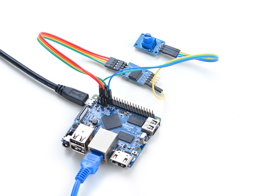
4.1 连接NanoPi M1
连接说明:
| Matrix-Potentiometer | |
| GND | NanoPi M1 Pin9 |
| 5V | NanoPi M1 Pin2 |
| S | Matrix-Analog_to_Digital_Converter A0 |
4.2 连接NanoPi 2
连接说明:
| Matrix-Potentiometer | |
| GND | NanoPi 2 Pin9 |
| 5V | NanoPi 2 Pin2 |
| S | Matrix-Analog_to_Digital_Converter A0 |
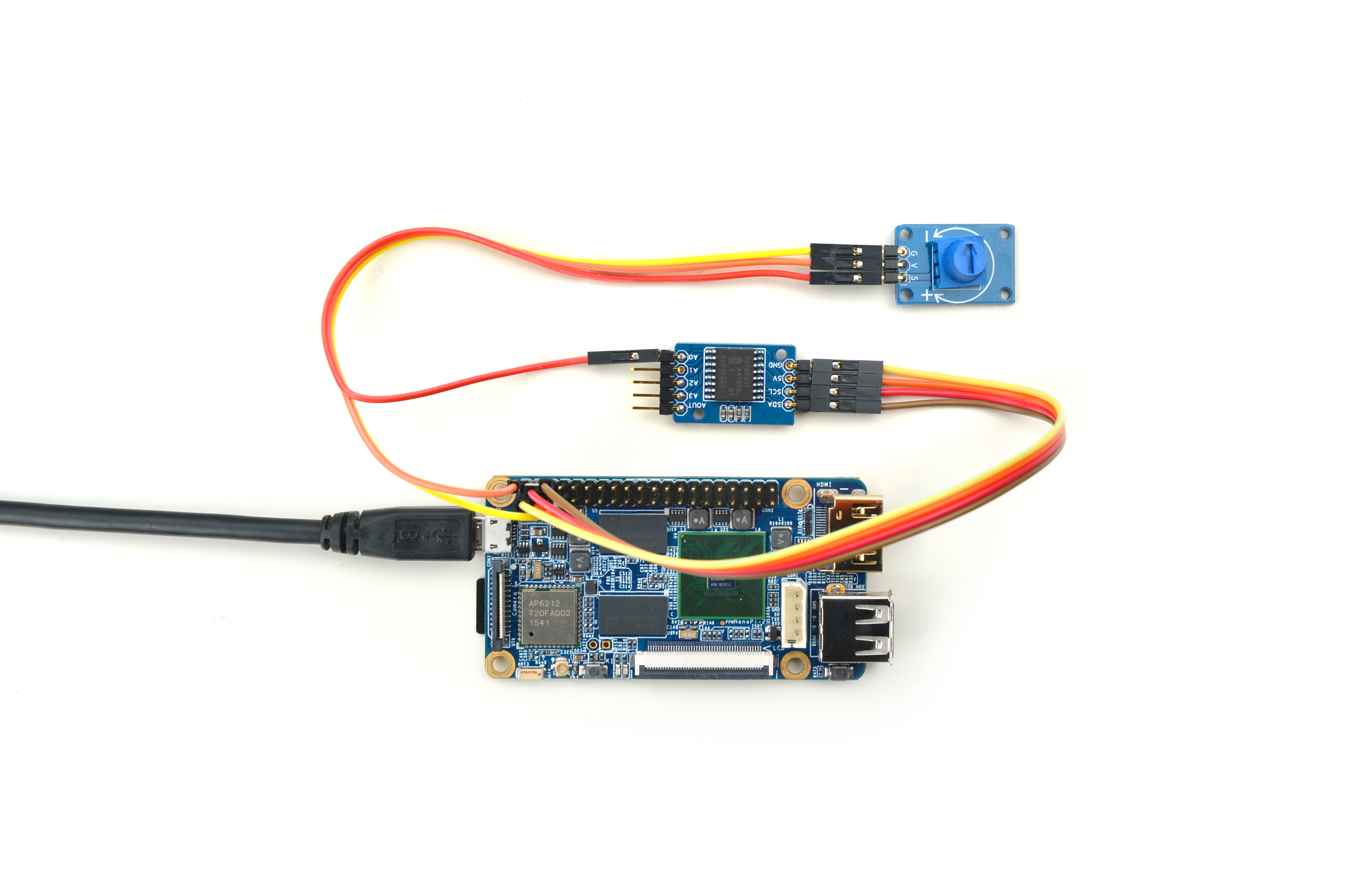
4.3 连接NanoPi M2 / NanoPi 2 Fire
NanoPi M2和NanoPi 2 Fire的40 Pin引脚定义是一模一样的,所以它们操作Matrix配件的步骤是一样的,这里仅以NanoPi M2为例。
参考下图连接模块:
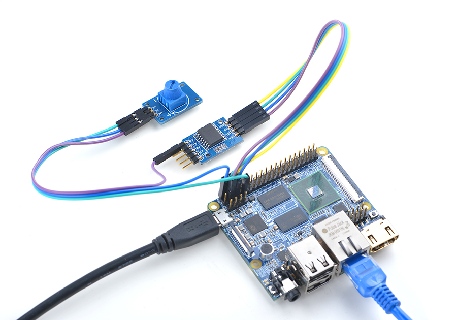
连接说明:
| Matrix-Potentiometer | |
| GND | NanoPi M2 Pin9 |
| 5V | NanoPi M2 Pin2 |
| S | Matrix-Analog_to_Digital_Converter A0 |
4.4 连接NanoPC-T2
参考下图连接模块:
Matrix-Potentiometer_NanoPC-T2
连接说明:
| Matrix-Potentiometer | |
| GND | NanoPC-T2 USB Host GND |
| 5V | NanoPC-T2 USB Host 5V |
| S | Matrix-Analog_to_Digital_Converter A0 |
5 编译运行测试程序
启动开发板并运行Debian系统,进入系统后克隆Matrix代码仓库:
$ apt-get update && apt-get install git
$ git clone https://github.com/friendlyarm/matrix.git
克隆完成后会得到一个名为matrix的目录。
编译并安装Matrix:
$ cd matrix
$ make && make install
运行测试程序:
$ matrix-adc注意:此模块并不支持热插拔,启动系统前需要确保硬件连接正确。
运行效果如下:
The channel0 value is 24606 代码说明
所有的开发板都共用一套Matrix代码,本模块的测试示例代码为matrix-analog_to_digital_converter,内容如下:
int main(int argc, char ** argv)
{
    int i = 0;
    int value = 0;
    int channel = 0;

    if (boardInit() < 0) {
        printf("Fail to init board\n");
        return -1;
    }

    if (argc == 2)
        channel = atoi(argv[1]);
    system("modprobe "DRIVER_MODULE);
    signal(SIGINT, intHandler);
    for (i=0; i<ADC_READ_TIMES; i++) {
        if (pcf8591Read(channel, &value) != -1) {
            printf("The channel%d value is %d\n", channel, value);
        } else {
            printf("Fail to get channel%d value\n", channel);
        }
    }
    system("rmmod "DRIVER_MODULE);

    return 0;
}
API说明参考维基:Matrix API reference manual
7 Resources
8 Update Log
8.1 Feb-24-2016
- Added link to the Chinese version
