Difference between revisions of "Matrix - Relay"
(→Introduction) |
|||
| Line 7: | Line 7: | ||
==Features== | ==Features== | ||
* 1 Form C | * 1 Form C | ||
| − | * | + | * 5V supply voltage, GPIO signal: 3.3/5V |
| − | * | + | * Current on-contact up to 10A |
| − | * | + | * LED indicator |
| − | * 2. | + | * 2.54 mm spacing pin |
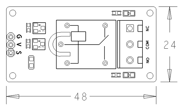
| − | * | + | * PCB dimension (mm): 24 x 48 |
[[File:relaypcb.png|frameless|400px|继电器PCB]] | [[File:relaypcb.png|frameless|400px|继电器PCB]] | ||
| Line 27: | Line 27: | ||
==Basic Device Operation== | ==Basic Device Operation== | ||
| + | This is an SPDT relay. Its supply voltage is 5V and current on-contact is up to 10A. | ||
这是一个单刀双掷继电器,线圈电压为直流5V,触点电流可达10A,适合驱动直流或交流大功率负载。NO为常开触点,NC为常闭触点,COM为公共触点。当向S引脚施加高电平,继电器线圈导通,此时NO触点断开,NC触点闭合。 | 这是一个单刀双掷继电器,线圈电压为直流5V,触点电流可达10A,适合驱动直流或交流大功率负载。NO为常开触点,NC为常闭触点,COM为公共触点。当向S引脚施加高电平,继电器线圈导通,此时NO触点断开,NC触点闭合。 | ||
Revision as of 10:11, 24 September 2015
Contents
1 Introduction
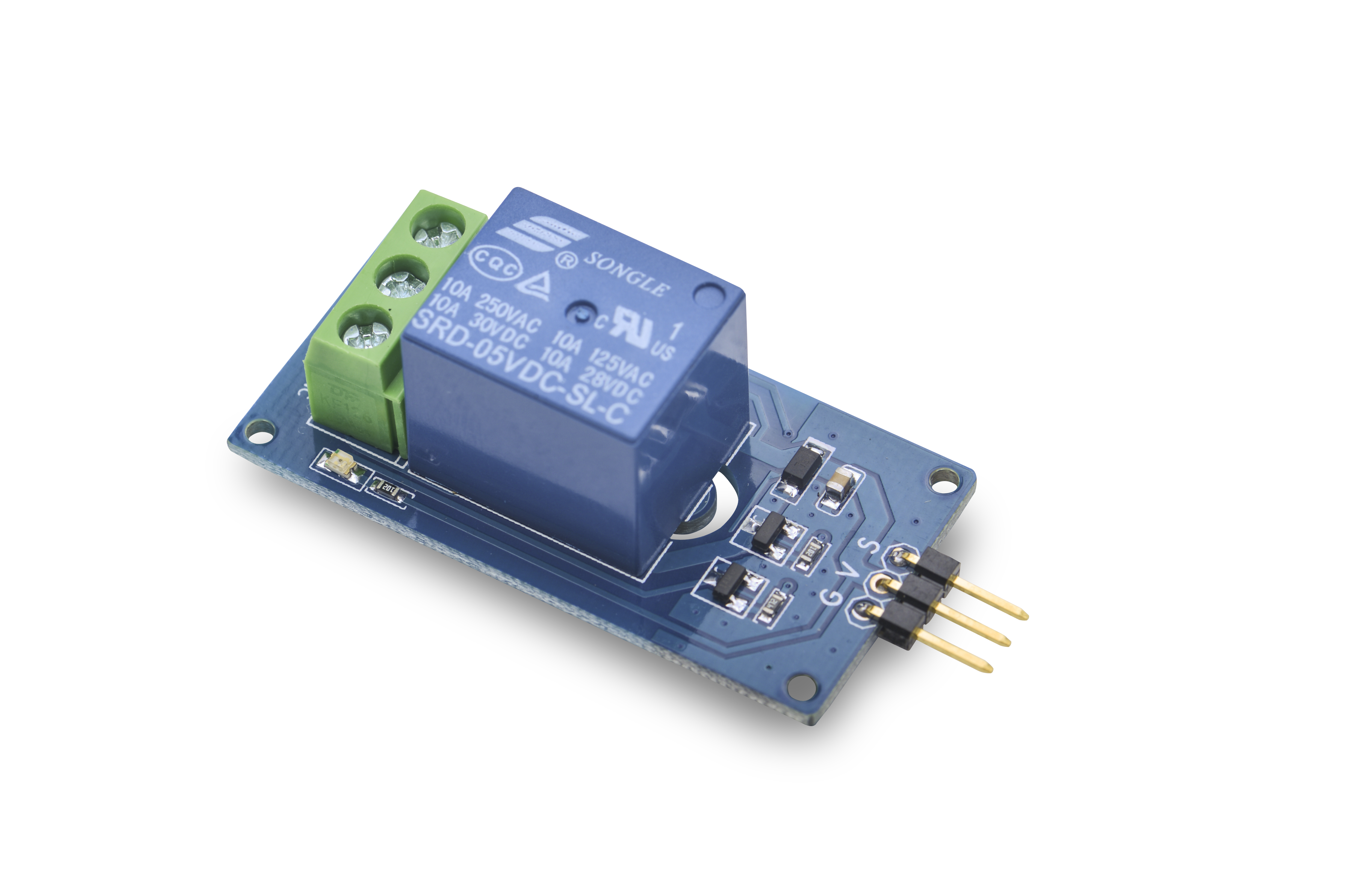
- The Matrix-Relay module is a SPDT relay which is an electrically operated switch. Relays are used where it is necessary to control a circuit by a low-power signal. In a electric system it is used to protect electrical circuits from overload or faults.
2 Features
- 1 Form C
- 5V supply voltage, GPIO signal: 3.3/5V
- Current on-contact up to 10A
- LED indicator
- 2.54 mm spacing pin
- PCB dimension (mm): 24 x 48
- Pin Description:
| Pin | Description |
| S | GPIO |
| V | Supply Voltage 5V |
| G | Ground |
3 Basic Device Operation
This is an SPDT relay. Its supply voltage is 5V and current on-contact is up to 10A. 这是一个单刀双掷继电器,线圈电压为直流5V,触点电流可达10A,适合驱动直流或交流大功率负载。NO为常开触点,NC为常闭触点,COM为公共触点。当向S引脚施加高电平,继电器线圈导通,此时NO触点断开,NC触点闭合。
4 Download Matrix Source Code
All the matrix modules' code samples are open source. They are maintained on GitHub - git://github.com/friendlyarm/matrix.git
Each branch in this hub contains the matrix modules' code samples for a board that the matrix modules can work with.
- The nanopi branch contains the matrix modules' code samples for the NanoPi
- The tiny4412 branch contains the matrix modules' code samples for the Tiny4412
- The raspberrypi branch contains the matrix modules' code samples for the RaspberryPi
Please follow the steps below to get the source code:
Install the git utility on a PC running Ubuntu14.04
$ sudo apt-get install git
Clone the matrix code from GitHub
$ git clone git://github.com/friendlyarm/matrix.git
If this is successful a "matrix" directory will be generated, which will contain all the matrix modules' code samples.
5 Connect to NanoPi
5.1 Preparations
Please install a Debian on a NanoPi and an appropriate cross compiler on a PC. Please refer to wiki:NanoPi
Compile a NanoPi kernel. Note: please use the kernel's source code from the nanopi-v4.1.y-matrix branch.
$ git clone https://github.com/friendlyarm/linux-4.x.y.git
$ cd linux-4.x.y
$ git checkout nanopi-v4.1.y-matrix
$ make nanopi_defconfig
$ touch .scmversion
$ make
5.2 Hardware Connection
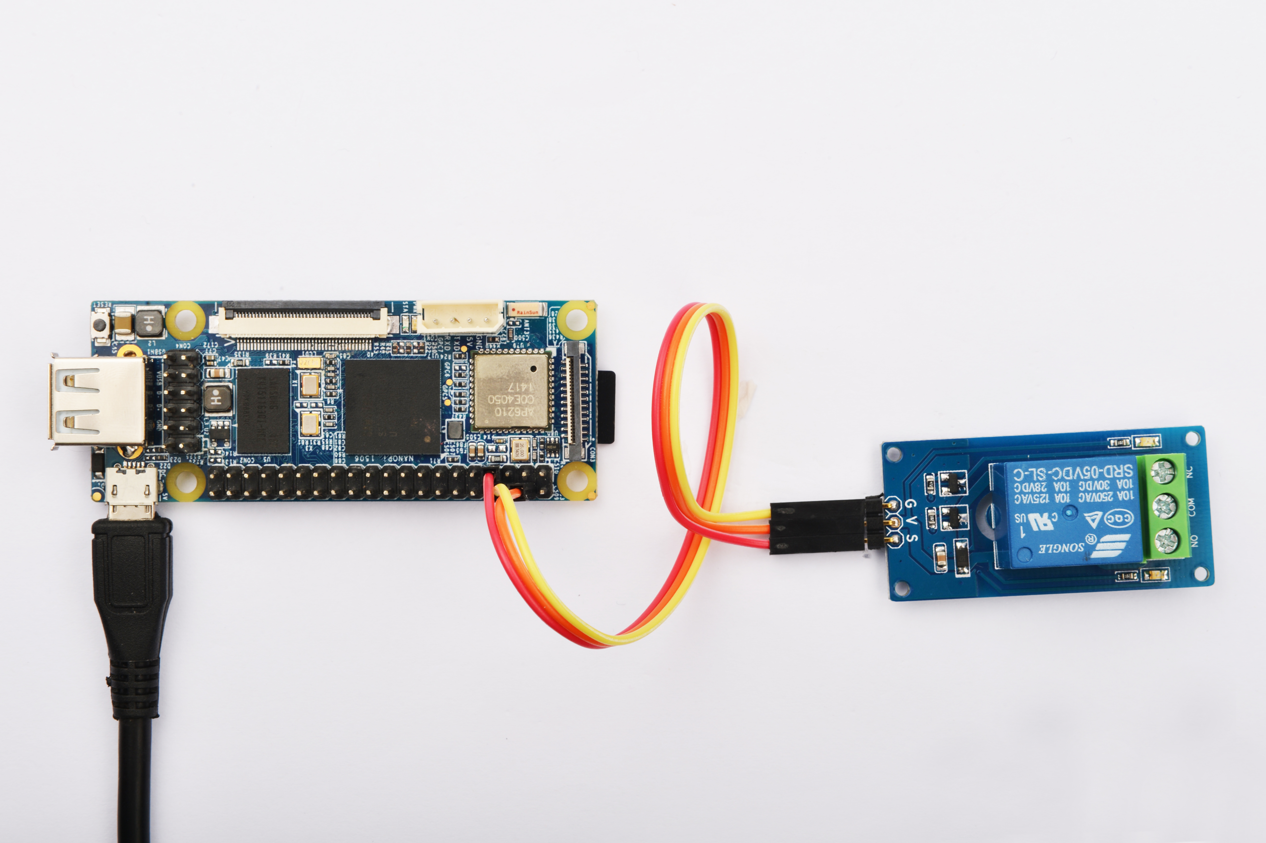
Please refer to the following connection diagram to connect the Matrix-Relay to the NanoPi

Connection Details:
| Matrix-LED | NanoPi |
| S | Pin7 |
| V | Pin4 |
| G | Pin6 |
5.3 Compile Test Program
Please login the matrix hub and enter the nanopi branch
$ cd matrix
$ git checkout nanopi
Compile the matrix code
$ make CROSS_COMPILE=arm-linux- clean
$ make CROSS_COMPILE=arm-linux-
$ make CROSS_COMPILE=arm-linux- install
Note: please make sure to install the cross compiler "arm-linux-gcc-4.4.3" on your PC, which is used to compile files for the NanoPi-Debian.
Generated library files are under the "install/lib" directory. Applications are under the "install/usr/bin" directory. The test program for the "Matrix-Relay" module is "matrix-relay".
5.4 Run Test Program
Please copy the library files and test program to the NanoPi
$ cp install/usr/bin/* nanopi_rootfs/usr/bin/
$ cp install/lib/* nanopi_rootfs/lib/ -d
Power on the NanoPi and run the following command in Debian's terminal
$ matrix-relay5.5 Code Sample
#include <stdio.h>
#include <string.h>
#include "libfahw.h"

int main(int argc, char ** argv)
{
    char *status = "off";
    if (argc != 2) {
        printf("Set relay on\n");
    } else {
        status = argv[1];
        printf("Set relay %s\n", argv[1]);
    }

    int pin = GPIO_PIN1;
    int ret = -1;
    if ((ret = exportGPIOPin(pin)) != 0) {
        printf("exportGPIOPin(%d) failed!", pin);
    }
    if ((ret = setGPIODirection(pin, GPIO_OUT)) != 0) {
        printf("setGPIODirection(%d) failed", pin);
    }

    if (strcmp(status, "on") == 0) {
        ret = setGPIOValue(pin, GPIO_HIGH);
    } else if (strcmp(status, "off") == 0) {
        ret = setGPIOValue(pin, GPIO_LOW);
    }
    return ret;
}
6 Connect to Tiny4412
6.1 Preparations
Please refer to the Tiny4412's user's manual to install a UbuntuCore on the Tiny4412 and install an appropriate cross compiler on a PC.
Note: only the Tiny4412SDK-1506 carrier board can work with this module.
6.2 Hardware Connection
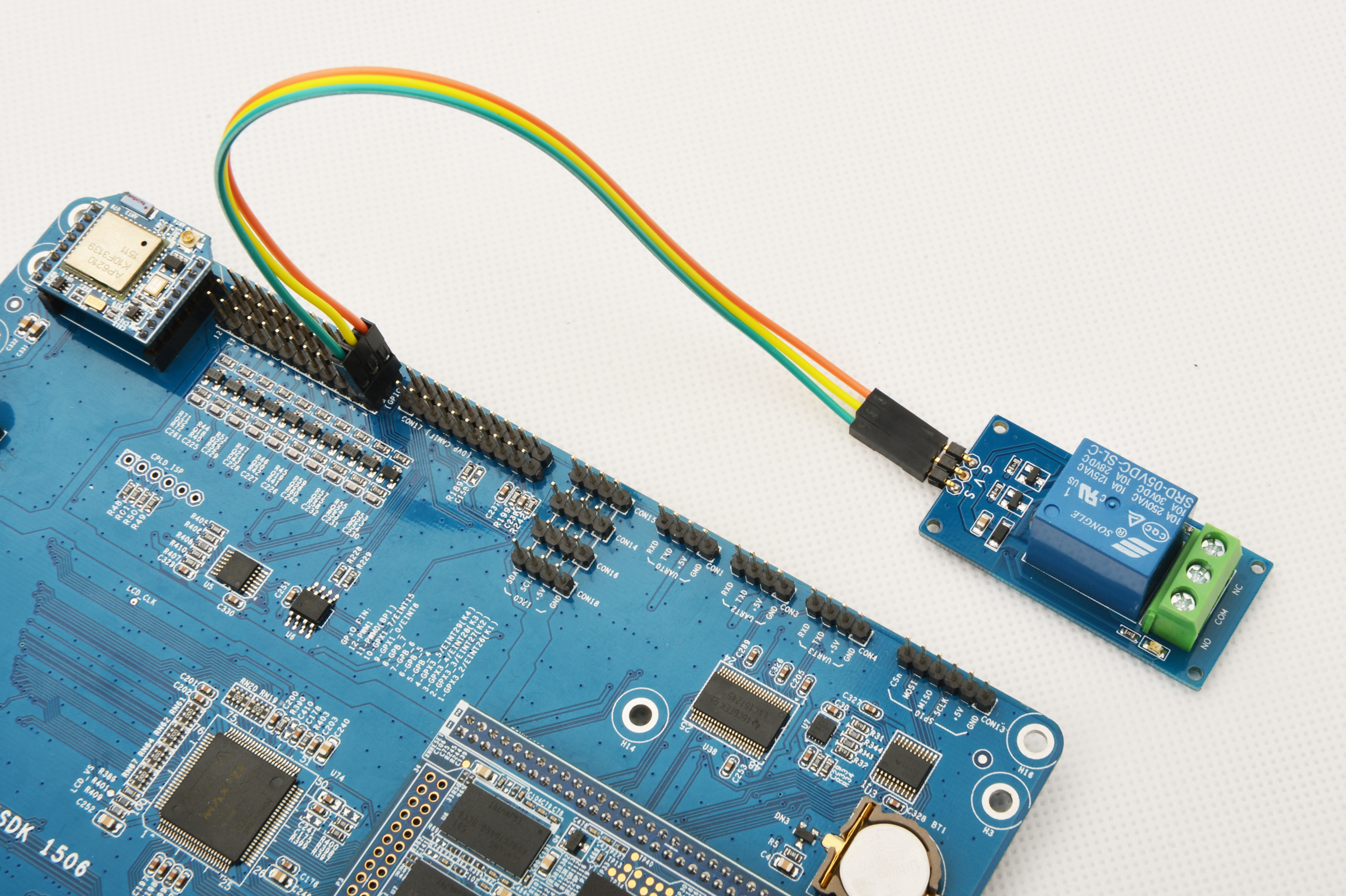
Please refer to the following diagram to connect the Matrix-Relay to the Tiny4412

Connection Details:
| Matrix-LED | Tiny4412 |
| S | GPIO1 S |
| V | GPIO1 5V |
| G | GPIO1 GND |
6.3 Compile Test Program
Please login the Matrix hub and enter the matrix-tiny4412 branch
$ cd matrix
$ git checkout tiny4412
Compile the matrix code
$ make CROSS_COMPILE=arm-linux-gnueabihf- clean
$ make CROSS_COMPILE=arm-linux-gnueabihf-
$ make CROSS_COMPILE=arm-linux-gnueabihf- install
Note: please make sure to install the cross compiler "arm-linux-gnueabihf-gcc-4.7.3" on your PC, which is used to compile files for the Tiny4412-UbuntuCore.
Generated library files are under the "install/lib" directory. Applications are under the "install/usr/bin" directory. The test program for the "Matrix-Relay" module is "matrix-relay".
6.4 Run Test Program
Please copy the library files and test program to the Tiny4412
$ cp install/usr/bin/* tiny4412_rootfs/usr/bin/
$ cp install/lib/* tiny4412_rootfs/lib/ -d
Power on the Tiny4412 and run the following command in UbuntuCore's terminal
$ matrix-relay6.5 Code Sample
#include <stdio.h>
#include <string.h>
#include "libfahw.h"

int main(int argc, char ** argv)
{
    char *status = "off";
    if (argc != 2) {
        printf("Set relay on\n");
    } else {
        status = argv[1];
        printf("Set relay %s\n", argv[1]);
    }

    int pin = GPIO_PIN1;
    int ret = -1;
    if ((ret = exportGPIOPin(pin)) != 0) {
        printf("exportGPIOPin(%d) failed!", pin);
    }
    if ((ret = setGPIODirection(pin, GPIO_OUT)) != 0) {
        printf("setGPIODirection(%d) failed", pin);
    }

    if (strcmp(status, "on") == 0) {
        ret = setGPIOValue(pin, GPIO_HIGH);
    } else if (strcmp(status, "off") == 0) {
        ret = setGPIOValue(pin, GPIO_LOW);
    }
    return ret;
}

