Difference between revisions of "SOM-RK3399 Dev Kit"
From FriendlyELEC WiKi
(→Layout) |
(→Layout) |
||
| Line 45: | Line 45: | ||
* '''HDMI IN''' | * '''HDMI IN''' | ||
| − | * 要使用HDMI IN功能,需要短接J2。 | + | ** 要使用HDMI IN功能,需要短接J2。 |
* '''MIPI-CSI''' | * '''MIPI-CSI''' | ||
| − | + | :: 0.5mm FPC Connector | |
| + | :: MIPI-CSI2 can be configured to MIPI-DSI. | ||
| + | ::{| class="wikitable" | ||
| + | |- | ||
| + | |'''Pin#''' || '''MIPI-CSI1''' || '''MIPI-CSI2''' || '''Description ''' | ||
| + | |- | ||
| + | |1 || VCC5V0_SYS || VCC5V0_SYS || 5V Power ouput | ||
| + | |- | ||
| + | |2 || VCC5V0_SYS || VCC5V0_SYS || 5V Power ouput | ||
| + | |- | ||
| + | |3 || GND || GND || Return current path | ||
| + | |- | ||
| + | |4 || VCC_CSI_AF2.8V || VCC_CSI_AF2.8V || 2.8V Power for VCM | ||
| + | |- | ||
| + | |5 || VCC_CSI_1.2V || VCC_CSI_1.2V || 1.2V Power for image sensor core circuit | ||
| + | |- | ||
| + | |6 || VCC1V8_CAM || VCC1V8_CAM || 1.8V power for I/O circuit | ||
| + | |- | ||
| + | |7 || VCC_CSI_2.8V || VCC_CSI_2.8V || 2.8V power for image sensor analog circuit | ||
| + | |- | ||
| + | |8 || VCC_CSI_1.0V || VCC_CSI_1.0V || 1.0V Power for image sensor core circuit | ||
| + | |- | ||
| + | |9 || I2C1_SCL || I2C2_SCL || 1.8V I2C clock signal | ||
| + | |- | ||
| + | |10 || I2C1_SDA || I2C2_SDA || 1.8V I2C data signal | ||
| + | |- | ||
| + | |11 || MIPI_CSI0_RST || MIPI_CSI1_RST || reset camera module | ||
| + | |- | ||
| + | |12 || MIPI_CSI0_PWN || MIPI_CSI1_PWN || Power down camera module | ||
| + | |- | ||
| + | |13 || GND || GND || Return current path | ||
| + | |- | ||
| + | |14 || GPIO2_B3_CIF_CLKOUTA || GPIO2_B3_CIF_CLKOUTA || MCLK to camera module | ||
| + | |- | ||
| + | |15 || GND || GND || Return current path | ||
| + | |- | ||
| + | |16 || MIPI_RX0_D3P || MIPI_TX1/RX1_D3P || MIPI CSI positive differential data line transceiver output | ||
| + | |- | ||
| + | |17 || MIPI_RX0_D3N || MIPI_TX1/RX1_D3N || MIPI CSI negative differential data line transceiver output | ||
| + | |- | ||
| + | |18 || GND || GND || Return current path | ||
| + | |- | ||
| + | |19 || MIPI_RX0_D2P || MIPI_TX1/RX1_D2P || MIPI CSI positive differential data line transceiver output | ||
| + | |- | ||
| + | |20 || MIPI_RX0_D2N || MIPI_TX1/RX1_D2N || MIPI CSI negative differential data line transceiver output | ||
| + | |- | ||
| + | |21 || GND || GND || Return current path | ||
| + | |- | ||
| + | |22 || MIPI_RX0_D1P || MIPI_TX1/RX1_D1P || MIPI CSI positive differential data line transceiver output | ||
| + | |- | ||
| + | |23 || MIPI_RX0_D1N || MIPI_TX1/RX1_D1N || MIPI CSI negative differential data line transceiver output | ||
| + | |- | ||
| + | |24 || GND || GND || Return current path | ||
| + | |- | ||
| + | |25 || MIPI_RX0_CLKP || MIPI_TX1/RX1_CLKP || MIPI CSI positive differential clock line transceiver output | ||
| + | |- | ||
| + | |26 || MIPI_RX0_CLKN || MIPI_TX1/RX1_CLKN || MIPI CSI negative differential clock line transceiver output | ||
| + | |- | ||
| + | |27 || GND || GND || Return current path | ||
| + | |- | ||
| + | |28 || MIPI_RX0_D0P || MIPI_TX1/RX1_D0P || MIPI CSI positive differential data line transceiver output | ||
| + | |- | ||
| + | |29 || MIPI_RX0_D0N || MIPI_TX1/RX1_D0N || MIPI CSI negative differential data line transceiver output | ||
| + | |- | ||
| + | |30 || GND || GND || Return current path | ||
| + | |} | ||
* '''MIPI-DSI''' | * '''MIPI-DSI''' | ||
Revision as of 10:18, 24 May 2019
Contents
1 Introduction
2 Hardware Spec
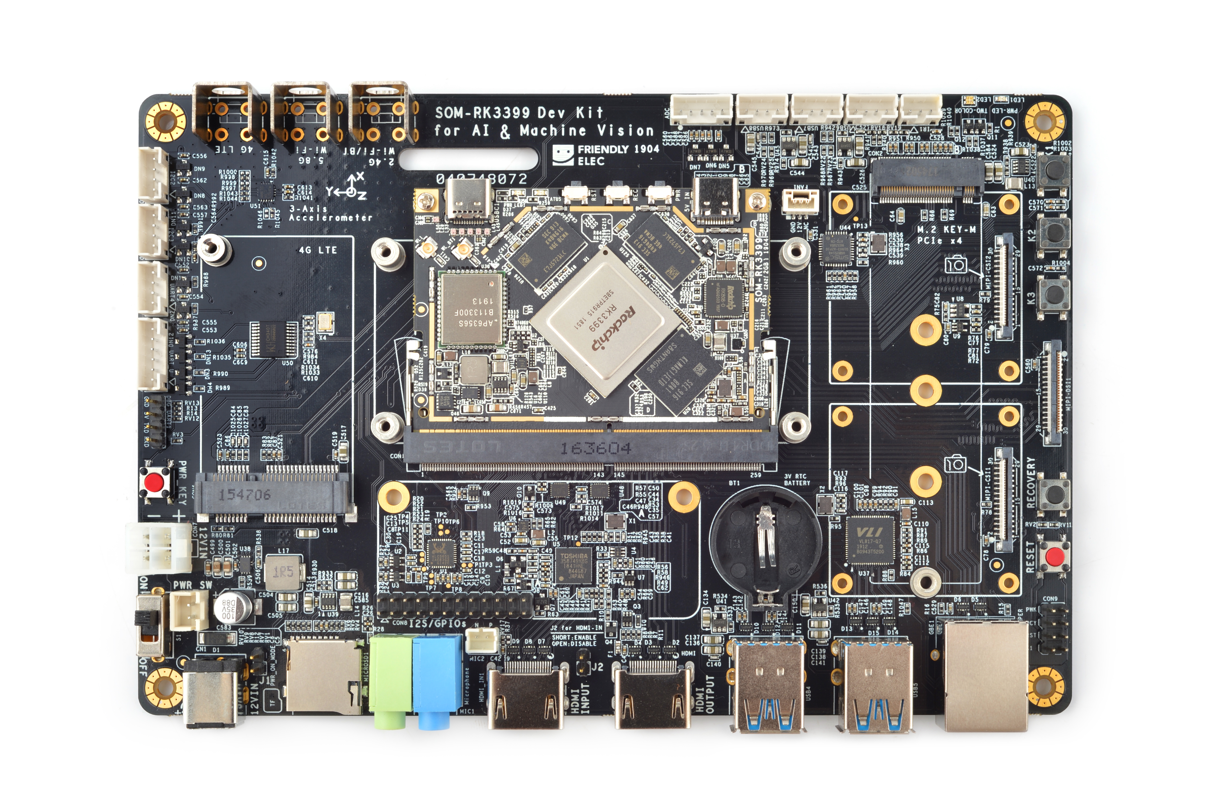
- CPU Board: SOM-RK3399, 2GB DDR3,16GB eMMC
- connectivity :
- IEEE 802.11b/g/n/AC Wi-Fi
- Bluetooth 4.1
- One 10/100/1000M Ethernet Port
- One MiniPCIe Socket and microSIM slot for 4G LTE module
- USB
- One USB Type-C Port
- 4xUSB3.0 Type-A port
- 3xUSB2.0 PH2.0 connector
- Video out
- One HDMI Type-A, support HDMI 2.0a, supports 4K@60Hz,HDCP 1.4/2.2
- DisplayPort 1.2 Alt Mode on USB Type-C
- one eDP 1.3(4-Lane,10.8Gbps)
- one or two 4-Lane MIPI-DSI
- Video In/Camera interface
- One HDMI IN, support 1080p@30fps, 1280x720@60fps video and audio recording
- one or two 4-Lane MIPI-CSI, up to 13MPix/s,supports simultaneous input of dual camera data
- Audio
- One 3.5mm stereo headphone Jack
- One 3.5mm microphone Jack
- One PH2.0 connector for microphone
- One mciroSD card slot
- One PCIe x4 M.2 Key-M Socket
- Button: PowerKey, Reset, Recovery, 3xUserKey
- LED: One Power LED, One user dual color led
- RTC:CR2032 3V battery holder
- others: 3xADCs,1xIR-IN,2xI2Cs,2xUARTs,1x8ch-I2S,3xGPIOS,1xSPDIF-TX,1x12V cooling fan interface
- Power Supply: DC 12V
- 4-layer PCB
3 Software Features
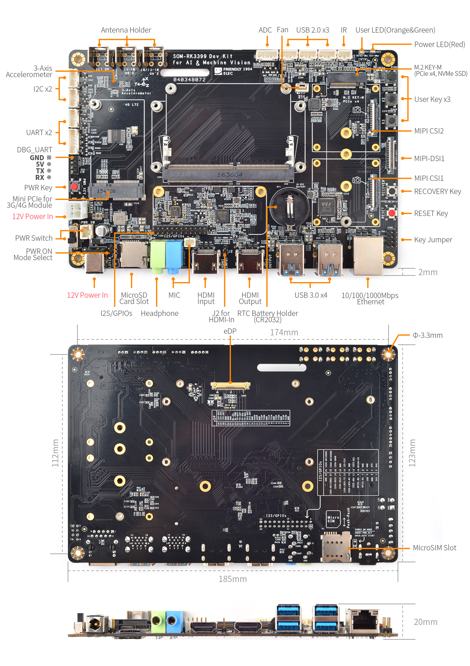
4 Diagram, Layout and Dimension
4.1 Layout
- HDMI IN
- 要使用HDMI IN功能,需要短接J2。
- MIPI-CSI
- 0.5mm FPC Connector
- MIPI-CSI2 can be configured to MIPI-DSI.
Pin# MIPI-CSI1 MIPI-CSI2 Description 1 VCC5V0_SYS VCC5V0_SYS 5V Power ouput 2 VCC5V0_SYS VCC5V0_SYS 5V Power ouput 3 GND GND Return current path 4 VCC_CSI_AF2.8V VCC_CSI_AF2.8V 2.8V Power for VCM 5 VCC_CSI_1.2V VCC_CSI_1.2V 1.2V Power for image sensor core circuit 6 VCC1V8_CAM VCC1V8_CAM 1.8V power for I/O circuit 7 VCC_CSI_2.8V VCC_CSI_2.8V 2.8V power for image sensor analog circuit 8 VCC_CSI_1.0V VCC_CSI_1.0V 1.0V Power for image sensor core circuit 9 I2C1_SCL I2C2_SCL 1.8V I2C clock signal 10 I2C1_SDA I2C2_SDA 1.8V I2C data signal 11 MIPI_CSI0_RST MIPI_CSI1_RST reset camera module 12 MIPI_CSI0_PWN MIPI_CSI1_PWN Power down camera module 13 GND GND Return current path 14 GPIO2_B3_CIF_CLKOUTA GPIO2_B3_CIF_CLKOUTA MCLK to camera module 15 GND GND Return current path 16 MIPI_RX0_D3P MIPI_TX1/RX1_D3P MIPI CSI positive differential data line transceiver output 17 MIPI_RX0_D3N MIPI_TX1/RX1_D3N MIPI CSI negative differential data line transceiver output 18 GND GND Return current path 19 MIPI_RX0_D2P MIPI_TX1/RX1_D2P MIPI CSI positive differential data line transceiver output 20 MIPI_RX0_D2N MIPI_TX1/RX1_D2N MIPI CSI negative differential data line transceiver output 21 GND GND Return current path 22 MIPI_RX0_D1P MIPI_TX1/RX1_D1P MIPI CSI positive differential data line transceiver output 23 MIPI_RX0_D1N MIPI_TX1/RX1_D1N MIPI CSI negative differential data line transceiver output 24 GND GND Return current path 25 MIPI_RX0_CLKP MIPI_TX1/RX1_CLKP MIPI CSI positive differential clock line transceiver output 26 MIPI_RX0_CLKN MIPI_TX1/RX1_CLKN MIPI CSI negative differential clock line transceiver output 27 GND GND Return current path 28 MIPI_RX0_D0P MIPI_TX1/RX1_D0P MIPI CSI positive differential data line transceiver output 29 MIPI_RX0_D0N MIPI_TX1/RX1_D0N MIPI CSI negative differential data line transceiver output 30 GND GND Return current path
- MIPI-DSI
- eDP
- PCIex4 M.2
- PH2.0 connectors(USB2.0 I2C, UART, ADC, IR)
- Microphone
- Power Supply
- Fan & heatsink
- I2S/GPIOs
- LED & Button
- Button Jumper
5 Link to Rockchip Resources
- Link to Rockchip's resources: https://gitlab.com/friendlyelec/rk3399-nougat/tree/nanopc-t4-nougat/RKDocs
- RK3399 datasheet V1.6
- RK3399TRM V1.4


